US5329967A - Lever assembly for single-control mixing valve - Google Patents
Lever assembly for single-control mixing valve Download PDFInfo
- Publication number
- US5329967A US5329967A US08/091,239 US9123993A US5329967A US 5329967 A US5329967 A US 5329967A US 9123993 A US9123993 A US 9123993A US 5329967 A US5329967 A US 5329967A
- Authority
- US
- United States
- Prior art keywords
- seat
- plate
- stem
- valve
- lever
- Prior art date
- Legal status (The legal status is an assumption and is not a legal conclusion. Google has not performed a legal analysis and makes no representation as to the accuracy of the status listed.)
- Expired - Fee Related
Links
Images

Classifications
-
- F—MECHANICAL ENGINEERING; LIGHTING; HEATING; WEAPONS; BLASTING
- F16—ENGINEERING ELEMENTS AND UNITS; GENERAL MEASURES FOR PRODUCING AND MAINTAINING EFFECTIVE FUNCTIONING OF MACHINES OR INSTALLATIONS; THERMAL INSULATION IN GENERAL
- F16K—VALVES; TAPS; COCKS; ACTUATING-FLOATS; DEVICES FOR VENTING OR AERATING
- F16K31/00—Actuating devices; Operating means; Releasing devices
- F16K31/44—Mechanical actuating means
- F16K31/60—Handles
- F16K31/605—Handles for single handle mixing valves
-
- Y—GENERAL TAGGING OF NEW TECHNOLOGICAL DEVELOPMENTS; GENERAL TAGGING OF CROSS-SECTIONAL TECHNOLOGIES SPANNING OVER SEVERAL SECTIONS OF THE IPC; TECHNICAL SUBJECTS COVERED BY FORMER USPC CROSS-REFERENCE ART COLLECTIONS [XRACs] AND DIGESTS
- Y10—TECHNICAL SUBJECTS COVERED BY FORMER USPC
- Y10T—TECHNICAL SUBJECTS COVERED BY FORMER US CLASSIFICATION
- Y10T137/00—Fluid handling
- Y10T137/8593—Systems
- Y10T137/86493—Multi-way valve unit
- Y10T137/86549—Selective reciprocation or rotation
-
- Y—GENERAL TAGGING OF NEW TECHNOLOGICAL DEVELOPMENTS; GENERAL TAGGING OF CROSS-SECTIONAL TECHNOLOGIES SPANNING OVER SEVERAL SECTIONS OF THE IPC; TECHNICAL SUBJECTS COVERED BY FORMER USPC CROSS-REFERENCE ART COLLECTIONS [XRACs] AND DIGESTS
- Y10—TECHNICAL SUBJECTS COVERED BY FORMER USPC
- Y10T—TECHNICAL SUBJECTS COVERED BY FORMER US CLASSIFICATION
- Y10T137/00—Fluid handling
- Y10T137/8593—Systems
- Y10T137/86493—Multi-way valve unit
- Y10T137/86815—Multiple inlet with single outlet
-
- Y—GENERAL TAGGING OF NEW TECHNOLOGICAL DEVELOPMENTS; GENERAL TAGGING OF CROSS-SECTIONAL TECHNOLOGIES SPANNING OVER SEVERAL SECTIONS OF THE IPC; TECHNICAL SUBJECTS COVERED BY FORMER USPC CROSS-REFERENCE ART COLLECTIONS [XRACs] AND DIGESTS
- Y10—TECHNICAL SUBJECTS COVERED BY FORMER USPC
- Y10T—TECHNICAL SUBJECTS COVERED BY FORMER US CLASSIFICATION
- Y10T137/00—Fluid handling
- Y10T137/8593—Systems
- Y10T137/87056—With selective motion for plural valve actuator
- Y10T137/8708—Rotation of actuator arm about its pivot and its axis
Definitions
- the present invention relates to a single-control mixing valve. More particularly this invention concerns a lever assembly for such a valve.
- a standard single-control mixing valve has as described in German patent 3,426,236 of M. Pawelzik et al an upwardly directed stem extending along a stem axis and movable relative to a normally stationary valve axis for regulation of flow through the valve.
- This stem is controlled by a lever formed with a downwardly open socket that fits complimentarily over the stem so that tipping and pivoting the lever operates the valve.
- the lever is secured to the stem by a screw that passes through the lever and is threaded coaxially into the stem.
- a removable cap or cover disk on the lever hides this screw.
- Another object is the provision of such an improved lever assembly for a single-control mixing valve which overcomes the above-given disadvantages, that is which is attractive but which nonetheless maintains a solid connection between the lever and the valve stem.
- a single-control mixing valve has an upwardly directed stem extending along a stem axis and movable relative to a normally stationary valve axis for regulation of flow through the valve.
- a lever assembly has a flange element having a socket fitted complimentarily over the stem and a plate having a periphery and extending transversely of the valve axis, a first screw secures the flange element to the stem with the socket fitted over same, and a lever having a cup-shaped base part formed with a downwardly open seat complimentarily fittable with the plate and an arm projecting laterally from the base part.
- the seat has a laterally open recess, and a second screw secures the plate in the seat with a portion of the seat periphery projecting laterally into the recess.
- the second screw is threaded upwardly through the base part and engages upwardly and laterally against the plate in the seat to press the plate into the recess.
- the periphery is generally circularly and the recess receives between one-quarter and one-half of the periphery.
- the screw is diametrally opposite the recess relative to the valve axis.
- the plate has an upper face engaged upward with the seat and the periphery is substantially circular, and the screw extends at an acute angle of about 45° to the plate.
- the lever is of metal and the screw is underneath the arm.
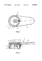
- FIG. 1 is a vertical section through the valve and lever assembly according to the invention
- FIG. 2 is a bottom view of the lever assembly
- FIG. 3 is a vertical section through the lever assembly.
- a standard mixing valve 1 has a cartridge 10 centered on a normally vertical axis 12 and provided with a square-sectionstem 11 extending along an axis 14 intersecting and normally forming a small acute angle with the axis 12.
- the cartridge 10 is contained within adecorative housing 13 of an otherwise unillustrated faucet assembly.
- a lever assembly comprises a solid-metal lever 2, a mounting element 3, and a screw 4.
- the lever 2 comprises a downwardly open cup-shaped base part 20 having a cylindrical downwardly extending skirt 21 defining a downwardly open seat 24 and a normally horizontally extending handle or arm 23 that typically projects out toward the user of the fitting incorporating the valve cartridge 10.
- the seat 24 is undercut at its side opposite the handle 2 in the form of a radially inwardly open semicircular groove 22.
- the mounting element 3 has a circular disk 34 with a planar upper face 31 that normally fits flatly against the downwardly directed circularly planar floor of the seat 24 and a downwardly directed square-section tubular socket 33 that fits complimentarily over the upper end of the stem11.
- a screw 35 engages through the element 2 and into the stem 11 to fix the part 3 on the stem 11.
- the rear edge of the element 3 is beveled at 30to fit in the seat groove 22 and the front part of the element 3 is angled off at 32 where it is engaged by the end of the screw 4 that extends at 45° to the axis 12.
- the groove 22 forms a 45° angle that complimentarily engages over the beveled edge 30.
- a recess 25 in the floorof the seat 25 accommodates the head of the screw 35 although it is possible to recess this head 35 in the top surface 31 of the disk 34 and thereby eliminate the need for this recess 25.
- the above-described assembly is put together by first fitting the element 3over the stem 11 and securing it in place with the screw 35. Then the seat 24 of the part 2 is fitted over the disk 34 and the rear edge 30 is fittedinto the seat 22 by sliding the part 2 forward. The screw 4 is then tightened to force the disk 34 tightly back into the seat 22 and press thefront edge up against the floor of the seat 24.
Abstract
Description
Claims (7)
Applications Claiming Priority (2)
| Application Number | Priority Date | Filing Date | Title |
|---|---|---|---|
| DE4223093A DE4223093A1 (en) | 1992-07-14 | 1992-07-14 | One-handle mixer valve |
| DE4223093 | 1992-07-14 |
Publications (1)
| Publication Number | Publication Date |
|---|---|
| US5329967A true US5329967A (en) | 1994-07-19 |
Family
ID=6463155
Family Applications (1)
| Application Number | Title | Priority Date | Filing Date |
|---|---|---|---|
| US08/091,239 Expired - Fee Related US5329967A (en) | 1992-07-14 | 1993-07-13 | Lever assembly for single-control mixing valve |
Country Status (7)
| Country | Link |
|---|---|
| US (1) | US5329967A (en) |
| EP (1) | EP0579111B1 (en) |
| JP (1) | JPH0658456A (en) |
| AT (1) | ATE129551T1 (en) |
| DE (2) | DE4223093A1 (en) |
| DK (1) | DK0579111T3 (en) |
| ES (2) | ES2081665T3 (en) |
Cited By (3)
| Publication number | Priority date | Publication date | Assignee | Title |
|---|---|---|---|---|
| US6736369B2 (en) | 2001-08-20 | 2004-05-18 | Moen Incorporated | ADA metering faucet mechanism |
| US20070151613A1 (en) * | 2004-01-14 | 2007-07-05 | Arno Hahn | Sanitary fitting |
| US9062796B2 (en) | 2013-01-11 | 2015-06-23 | Delta Faucet Company | Faucet handle assembly |
Families Citing this family (4)
| Publication number | Priority date | Publication date | Assignee | Title |
|---|---|---|---|---|
| DE19602158A1 (en) * | 1996-01-23 | 1997-07-24 | Grohe Kg Hans | Fixing device for operating handle of sanitary ware |
| DE19602161A1 (en) | 1996-01-23 | 1997-07-24 | Grohe Kg Hans | Sanitary fitting |
| KR101151733B1 (en) * | 2011-12-07 | 2012-06-15 | (주)일신오토클레이브 | Handle Combination Structure for Needle Valve |
| US11326715B2 (en) * | 2020-02-14 | 2022-05-10 | Delta Faucet Company | Snap-on faucet handle |
Citations (15)
| Publication number | Priority date | Publication date | Assignee | Title |
|---|---|---|---|---|
| DE2808349A1 (en) * | 1978-02-27 | 1979-09-06 | Hansa Metallwerke Ag | Hot and cold water mixing tap - has control arm with shell centred inside top cap, fitted with snap action |
| US4378029A (en) * | 1981-11-02 | 1983-03-29 | American Standard Inc. | Single control faucet |
| EP0092863A1 (en) * | 1982-04-26 | 1983-11-02 | Gevipi A.G. | Connecting device for the lever of a single-control mixing valve |
| US4449551A (en) * | 1980-06-28 | 1984-05-22 | Hans Grohe Gmbh & Co. | Mixing valve |
| DE3426236A1 (en) * | 1984-07-17 | 1986-01-23 | Friedrich Grohe Armaturenfabrik Gmbh & Co, 5870 Hemer | Securing and insulating body for screwed joints |
| US4610272A (en) * | 1983-10-19 | 1986-09-09 | Friedrich Grohe Armaturenfabrik Gmbh & Co. | Actuating device for a mixing valve |
| US4630643A (en) * | 1982-10-23 | 1986-12-23 | Hans Grohe Gmbh & Co. Kg | Valve, particularly mixing valve |
| US4651774A (en) * | 1984-07-20 | 1987-03-24 | Hansa Metallwerke Ag | Single-lever mixer |
| US4685487A (en) * | 1985-03-18 | 1987-08-11 | American Standard Inc. | Sanitary mixing valve |
| US4708172A (en) * | 1985-09-25 | 1987-11-24 | Vargarda Armatur Ab | Device at mixing valves |
| US4960154A (en) * | 1987-09-24 | 1990-10-02 | American Standard Inc. | Sanitary water valve |
| DE9017658U1 (en) * | 1990-10-06 | 1991-05-08 | Fa. Kludi-Armaturen Paul Scheffer, 5758 Froendenberg, De | |
| DE4113878A1 (en) * | 1990-05-10 | 1991-11-14 | Grohe Armaturen Friedrich | Hot and cold water mixing tap - is actuated by single lever which is secured by screwed bush |
| US5082023A (en) * | 1989-10-31 | 1992-01-21 | Staar S. A. | Single-handle faucet |
| US5148551A (en) * | 1989-03-10 | 1992-09-22 | Friedrich Grohe Armaturenfabrik Gmbh + Co. | Surface-mounting mixing valve |
-
1992
- 1992-07-14 DE DE4223093A patent/DE4223093A1/en not_active Withdrawn
-
1993
- 1993-06-01 JP JP5130650A patent/JPH0658456A/en active Pending
- 1993-07-08 ES ES93110911T patent/ES2081665T3/en not_active Expired - Lifetime
- 1993-07-08 EP EP93110911A patent/EP0579111B1/en not_active Expired - Lifetime
- 1993-07-08 AT AT93110911T patent/ATE129551T1/en not_active IP Right Cessation
- 1993-07-08 DE DE59300810T patent/DE59300810D1/en not_active Expired - Lifetime
- 1993-07-08 DK DK93110911.0T patent/DK0579111T3/en active
- 1993-07-13 US US08/091,239 patent/US5329967A/en not_active Expired - Fee Related
- 1993-07-14 ES ES9301970U patent/ES1025312Y/en not_active Expired - Lifetime
Patent Citations (15)
| Publication number | Priority date | Publication date | Assignee | Title |
|---|---|---|---|---|
| DE2808349A1 (en) * | 1978-02-27 | 1979-09-06 | Hansa Metallwerke Ag | Hot and cold water mixing tap - has control arm with shell centred inside top cap, fitted with snap action |
| US4449551A (en) * | 1980-06-28 | 1984-05-22 | Hans Grohe Gmbh & Co. | Mixing valve |
| US4378029A (en) * | 1981-11-02 | 1983-03-29 | American Standard Inc. | Single control faucet |
| EP0092863A1 (en) * | 1982-04-26 | 1983-11-02 | Gevipi A.G. | Connecting device for the lever of a single-control mixing valve |
| US4630643A (en) * | 1982-10-23 | 1986-12-23 | Hans Grohe Gmbh & Co. Kg | Valve, particularly mixing valve |
| US4610272A (en) * | 1983-10-19 | 1986-09-09 | Friedrich Grohe Armaturenfabrik Gmbh & Co. | Actuating device for a mixing valve |
| DE3426236A1 (en) * | 1984-07-17 | 1986-01-23 | Friedrich Grohe Armaturenfabrik Gmbh & Co, 5870 Hemer | Securing and insulating body for screwed joints |
| US4651774A (en) * | 1984-07-20 | 1987-03-24 | Hansa Metallwerke Ag | Single-lever mixer |
| US4685487A (en) * | 1985-03-18 | 1987-08-11 | American Standard Inc. | Sanitary mixing valve |
| US4708172A (en) * | 1985-09-25 | 1987-11-24 | Vargarda Armatur Ab | Device at mixing valves |
| US4960154A (en) * | 1987-09-24 | 1990-10-02 | American Standard Inc. | Sanitary water valve |
| US5148551A (en) * | 1989-03-10 | 1992-09-22 | Friedrich Grohe Armaturenfabrik Gmbh + Co. | Surface-mounting mixing valve |
| US5082023A (en) * | 1989-10-31 | 1992-01-21 | Staar S. A. | Single-handle faucet |
| DE4113878A1 (en) * | 1990-05-10 | 1991-11-14 | Grohe Armaturen Friedrich | Hot and cold water mixing tap - is actuated by single lever which is secured by screwed bush |
| DE9017658U1 (en) * | 1990-10-06 | 1991-05-08 | Fa. Kludi-Armaturen Paul Scheffer, 5758 Froendenberg, De |
Cited By (4)
| Publication number | Priority date | Publication date | Assignee | Title |
|---|---|---|---|---|
| US6736369B2 (en) | 2001-08-20 | 2004-05-18 | Moen Incorporated | ADA metering faucet mechanism |
| US20040227122A1 (en) * | 2001-08-20 | 2004-11-18 | Lenart Robert A. | ADA metering faucet mechanism |
| US20070151613A1 (en) * | 2004-01-14 | 2007-07-05 | Arno Hahn | Sanitary fitting |
| US9062796B2 (en) | 2013-01-11 | 2015-06-23 | Delta Faucet Company | Faucet handle assembly |
Also Published As
| Publication number | Publication date |
|---|---|
| DK0579111T3 (en) | 1996-02-26 |
| ES1025312U (en) | 1993-12-16 |
| ES1025312Y (en) | 1994-06-01 |
| ES2081665T3 (en) | 1996-03-16 |
| JPH0658456A (en) | 1994-03-01 |
| EP0579111B1 (en) | 1995-10-25 |
| DE59300810D1 (en) | 1995-11-30 |
| DE4223093A1 (en) | 1994-01-20 |
| EP0579111A1 (en) | 1994-01-19 |
| ATE129551T1 (en) | 1995-11-15 |
Similar Documents
| Publication | Publication Date | Title |
|---|---|---|
| US5165121A (en) | Fabricated faucet spout | |
| CA2206684A1 (en) | Top mounting faucet assembly | |
| US5329967A (en) | Lever assembly for single-control mixing valve | |
| CA2089637C (en) | Power fuel tank cover for automobiles | |
| US4760861A (en) | Faucet manifold | |
| US4134570A (en) | Two volume flush valve | |
| US5172457A (en) | Urn with top seal, bayonet closure and base arrangement with seal | |
| CA3107589C (en) | Snap-on faucet handle | |
| US4069543A (en) | Glide castors | |
| JPH0681383A (en) | Water/hot water mixing device | |
| US3950937A (en) | Structure of water-tight watch case | |
| AU4964393A (en) | Lockable pushbutton-distributor for aerosol valve | |
| US2743461A (en) | Insert nut and flange | |
| JP3218916B2 (en) | Single lever mixing faucet | |
| US3034150A (en) | Sink structure | |
| CA2068645A1 (en) | Single-lever mixer | |
| EP0343312A3 (en) | Ceramics disc shutter for faucets | |
| JP3304958B2 (en) | Single lever mixing faucet | |
| US5850846A (en) | Handle assembly for single-control valve | |
| GB2098854A (en) | Bottle container | |
| JPH08285126A (en) | Water faucet lever handle | |
| US3289294A (en) | Can opener assembly | |
| JPS642661Y2 (en) | ||
| JPS6215203B2 (en) | ||
| JPH0532225Y2 (en) |
Legal Events
| Date | Code | Title | Description |
|---|---|---|---|
| AS | Assignment |
Owner name: FRIEDRICH GROHE AKTIENGESELLSCHAFT, GERMANY Free format text: ASSIGNMENT OF ASSIGNORS INTEREST;ASSIGNOR:GNAUERT, WERNER;REEL/FRAME:006639/0043 Effective date: 19930609 |
|
| FPAY | Fee payment |
Year of fee payment: 4 |
|
| AS | Assignment |
Owner name: FRIEDRICH GROHE AG & CO. KG, GERMANY Free format text: CHANGE OF NAME;ASSIGNOR:FRIEDRICH GROHE AG;REEL/FRAME:010822/0875 Effective date: 20000328 |
|
| FPAY | Fee payment |
Year of fee payment: 8 |
|
| REMI | Maintenance fee reminder mailed | ||
| LAPS | Lapse for failure to pay maintenance fees | ||
| STCH | Information on status: patent discontinuation |
Free format text: PATENT EXPIRED DUE TO NONPAYMENT OF MAINTENANCE FEES UNDER 37 CFR 1.362 |
|
| FP | Lapsed due to failure to pay maintenance fee |
Effective date: 20060719 |