US5329841A - Piston-slide-valve - Google Patents
Piston-slide-valve Download PDFInfo
- Publication number
- US5329841A US5329841A US07/849,732 US84973292A US5329841A US 5329841 A US5329841 A US 5329841A US 84973292 A US84973292 A US 84973292A US 5329841 A US5329841 A US 5329841A
- Authority
- US
- United States
- Prior art keywords
- piston
- bore
- wire
- oil groove
- erosion
- Prior art date
- Legal status (The legal status is an assumption and is not a legal conclusion. Google has not performed a legal analysis and makes no representation as to the accuracy of the status listed.)
- Expired - Fee Related
Links
Images


Classifications
-
- F—MECHANICAL ENGINEERING; LIGHTING; HEATING; WEAPONS; BLASTING
- F16—ENGINEERING ELEMENTS AND UNITS; GENERAL MEASURES FOR PRODUCING AND MAINTAINING EFFECTIVE FUNCTIONING OF MACHINES OR INSTALLATIONS; THERMAL INSULATION IN GENERAL
- F16K—VALVES; TAPS; COCKS; ACTUATING-FLOATS; DEVICES FOR VENTING OR AERATING
- F16K27/00—Construction of housing; Use of materials therefor
- F16K27/04—Construction of housing; Use of materials therefor of sliding valves
- F16K27/041—Construction of housing; Use of materials therefor of sliding valves cylindrical slide valves
-
- B—PERFORMING OPERATIONS; TRANSPORTING
- B23—MACHINE TOOLS; METAL-WORKING NOT OTHERWISE PROVIDED FOR
- B23H—WORKING OF METAL BY THE ACTION OF A HIGH CONCENTRATION OF ELECTRIC CURRENT ON A WORKPIECE USING AN ELECTRODE WHICH TAKES THE PLACE OF A TOOL; SUCH WORKING COMBINED WITH OTHER FORMS OF WORKING OF METAL
- B23H9/00—Machining specially adapted for treating particular metal objects or for obtaining special effects or results on metal objects
- B23H9/005—Machining elongated bodies, e.g. rods
-
- B—PERFORMING OPERATIONS; TRANSPORTING
- B23—MACHINE TOOLS; METAL-WORKING NOT OTHERWISE PROVIDED FOR
- B23P—METAL-WORKING NOT OTHERWISE PROVIDED FOR; COMBINED OPERATIONS; UNIVERSAL MACHINE TOOLS
- B23P15/00—Making specific metal objects by operations not covered by a single other subclass or a group in this subclass
- B23P15/001—Making specific metal objects by operations not covered by a single other subclass or a group in this subclass valves or valve housings
-
- Y—GENERAL TAGGING OF NEW TECHNOLOGICAL DEVELOPMENTS; GENERAL TAGGING OF CROSS-SECTIONAL TECHNOLOGIES SPANNING OVER SEVERAL SECTIONS OF THE IPC; TECHNICAL SUBJECTS COVERED BY FORMER USPC CROSS-REFERENCE ART COLLECTIONS [XRACs] AND DIGESTS
- Y10—TECHNICAL SUBJECTS COVERED BY FORMER USPC
- Y10T—TECHNICAL SUBJECTS COVERED BY FORMER US CLASSIFICATION
- Y10T137/00—Fluid handling
- Y10T137/2496—Self-proportioning or correlating systems
- Y10T137/2559—Self-controlled branched flow systems
- Y10T137/2574—Bypass or relief controlled by main line fluid condition
- Y10T137/2605—Pressure responsive
- Y10T137/2607—With pressure reducing inlet valve
-
- Y—GENERAL TAGGING OF NEW TECHNOLOGICAL DEVELOPMENTS; GENERAL TAGGING OF CROSS-SECTIONAL TECHNOLOGIES SPANNING OVER SEVERAL SECTIONS OF THE IPC; TECHNICAL SUBJECTS COVERED BY FORMER USPC CROSS-REFERENCE ART COLLECTIONS [XRACs] AND DIGESTS
- Y10—TECHNICAL SUBJECTS COVERED BY FORMER USPC
- Y10T—TECHNICAL SUBJECTS COVERED BY FORMER US CLASSIFICATION
- Y10T137/00—Fluid handling
- Y10T137/8593—Systems
- Y10T137/86493—Multi-way valve unit
- Y10T137/86574—Supply and exhaust
- Y10T137/8667—Reciprocating valve
- Y10T137/86694—Piston valve
- Y10T137/8671—With annular passage [e.g., spool]
-
- Y—GENERAL TAGGING OF NEW TECHNOLOGICAL DEVELOPMENTS; GENERAL TAGGING OF CROSS-SECTIONAL TECHNOLOGIES SPANNING OVER SEVERAL SECTIONS OF THE IPC; TECHNICAL SUBJECTS COVERED BY FORMER USPC CROSS-REFERENCE ART COLLECTIONS [XRACs] AND DIGESTS
- Y10—TECHNICAL SUBJECTS COVERED BY FORMER USPC
- Y10T—TECHNICAL SUBJECTS COVERED BY FORMER US CLASSIFICATION
- Y10T29/00—Metal working
- Y10T29/49—Method of mechanical manufacture
- Y10T29/49405—Valve or choke making
Definitions
- the present invention concerns a piston-slide-valve including a housing, in which a piston with at least one oil groove and control edges is guided slidable in a bore.
- pistons With known piston-slide-valves of this type, the pistons are produced by turning, whereby the control edges are milled or cut thereon, hardened, ground and eventually perhaps being worked or machined by finishing and lapping.
- the bore for receiving the piston is produced by boring, grinding and honing.
- Disadvantageous hereby is that especially with small pistons, which for example have a diameter of 2 millimeters, there can be attained only a relatively small or nominal accuracy of the piston-running or travel play.
- Such pistons with high system pressures have inadequate or insufficient leakage values.
- Via relatively large production, manufacturing or finishing tolerances during the manufacture of the pistons and the receiving bore for the piston means, in an extreme situation large running play or travel can arise and occur in the installed or built-in condition or situation. Thereby high leakages can occur or arise, which with control of small oil flows are very disturbing.
- An object of the present invention basically is to embody and construct a valve of the generic type in such a manner that also small construction types, which work or operate at high pressures, only have a very small or nominal leakage and can be produced in a cost-advantageous and economical manner.
- the valve can be produced in an extremely cost-advantageous and economical manner, since the piston means can be produced in series or mass production. Via the wire erosion there are eliminated the mechanical working or machining stages, such as hardening, grinding, lapping, as well as the machining steps or stages of turning for production of circulating or surrounding oil grooves and cutting or milling for production of fine-control edges. Consequently thereby substantially all forms of oil grooves and fine-control edges can be produced or manufactured in the closest and most narrow tolerances. If especially for production or manufacture of the piston means there is employed a bearing pin or bed needle, which can be delivered and supplied in ⁇ m tolerances, then considerable costs can be saved, since the bearing pins are inexpensive or penny articles.
- the pistons can be produced in large series or mass production, since only small or nominal material removals are provided via wire-erosion.
- the bore for receiving the piston can be made or produced simply and in a cost-advantageous and economical manner. With the production and manufacture of the bore there can be attained a very high cylindrical characteristic or simplicity. Widening or expansion at the control edges, which can involve and carry a high leakage accompanying the same, are satisfactorily avoided and eliminated.
- the pistons can be manufactured or produced and made with the smallest or most nominal tolerances with very small measurements or dimensions, for example with a piston diameter of 2 mm and a length of 13 min.
- the pistons consequently have only very small or nominal leakage losses and consequently also can be installed to operate also at high pressures, for example up to 190 bar.
- the leakage is reduced to a minimum with a very low viscosity of maximum 5 qcm/min.
- disturbing edges, ridges or burrs which can occur or arise via a mechanical machining, are removed by the erosion or eroding, and are not pressed away, as for example during honing. Consequently the high leakages, which are very disturbing during the control of small oil flows, are hindered or prevented with certainty and the valve can be produced simply and in a straight forward manner with a very small or nominal cost involved therewith.
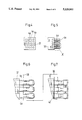
- FIG. 1 is a view that shows an axial section longitudinally of the piston-slide-valve having features in accordance with the present invention
- FIG. 2 is a view that shows an enlarged representation or illustration of a piston-slide-valve according to FIG. 1 in an elevational view;
- FIG. 3 is a view that shows a cross section taken along line A--A in FIG. 2;
- FIG. 4 is a plan view that shows a multiple holding or support for needle rollers as raw or unfinished members compartmented for the manufacture or production of the piston according to FIG. 1;
- FIG. 5 is a view that shows a multiple holding or compartmentalized support for needle rollers or pins according to FIG. 4 in a side view thereof;
- FIG. 6 is a view that shows in detail features within a circle-like configuration X in FIG. 5 in an enlarged illustration with drawn-in or marked travel path of an eroding or erosion wire for production of grooves and control edges of the piston according to FIG. 2;
- FIG. 7 is a view that shows in detail within the range of a circle-like configuration X in FIG. 5 in a position rotated by 90° relative to the position according to FIG. 6.
- the piston-slide-valve according to FIG. 1 comprises a housing 1, in which an adjustment screw 2, a bushing or sleeve 3, a piston 4, a sphere or ball5, a spring plate, disk or land 6, a spring 7 and a closure ball or sphere 8 are arranged.
- the piston is slidably or shiftably arranged in a bore 3a of the sleeve or bushing 3.
- the spring plate, disk or land 6 has a taperedextension 6a with an end-face depression or recess 6a', in which a sphere or ball 5 is supported.
- the spring 7 lies or engages with one end 7a a against a ring or annular collar 2a of the adjustment screw 2 and with theother end 7b thereof engaging or lying against a flange 6b of the spring plate, disk or land 6.
- the piston end 4a remote or away from the adjustment screw 2 lies in a location with spacing from the closure ball or sphere 8, so that a space or chamber 9a for the pressure medium, preferably oil, is formed between the ball and the piston end.
- the adjustment screw 2 is threaded or screwed into one end of the housing 1, over the other end of which the sleeve or bushing 3 projects. A bore 3a thereof is closed by the closure ball 8 at the projecting or extending bushing or sleeve end.
- the housing 1 has a working connection A, 19, 20 and has a tank connection T in the region of the spring 7.
- the pressure chamber 9a between the piston 4 and the closure ball 8 is connected via a pressure return line orconduit 9 with the working connection A, 19, 20.
- the sleeve or bushing 3 is provided with a transverse bore or hole 14, which connects the pressure chamber 9a with the pressure return line or conduit 9.
- the sleeve or bearing 3 additionally has further transverse bores or holes 15,16 and a control bore 17.
- the transverse bores or holes 15, 16 connect the pressure return line or conduit 9 with a pressure chamber 18 between the piston ends, while the control bore 17 connects or opens into a pressure connection 13 of the piston-slide-valve.
- the pressure medium can flow in the pressure chamber 18 via the control bore 17 upon corresponding positioning of the piston 4.
- the piston 4 is produced out of a needleroller.
- the piston 4 For formation of the pressure chamber 18 in the valve there is produced via wire erosion or eroding a preferably rotating or circulating groove on the piston 4.
- the piston 4 has very small measurements or dimensions; the piston 4 is preferably only 13 mm long and has a diameter of 2 mm. The piston diameter however also can lie in a range of, for example, only 1 mm.
- the pressure chamber 18 is limited or bounded outwardly by the bore wall 25of the bore 3a of the sleeve or bushing 3 and inwardly is limited by the peripheral or circumferential groove 22 and two grooves 26, 27 of the piston 4, which extend between two end segments or sections 23 and 24 (FIGS. 2, 3) of the piston 4.
- the one end segment or section 23 lying in the installed or built-in condition of the piston adjoining or neighboringthe closure ball 8 is longer than the other end section or segment 24 and approximately or substantially equally as long as the peripheral or circumferential groove 22. It is formed by four sides of the piston produced by wire erosion or eroding lying and located at right angles to each other, as will be explained still further herein.
- the middle or median tapered piston section or segment 28 remaining in the range of the peripheral or circumferential groove 22 has a square, preferably quadraticcross section as shown in FIG. 3. Between the tapered section or segment 28and the piston end section or segment 23 there is formed a ring or annular shoulder 29 having an edge that forms the control edge 11a.
- the tapered section or segment 28 proceeds at the other end over a further ring or annular shoulder 30, 31, 30', 31' extending parallel to the shoulder 29 having a transition into a partial segment or section 24' providing diametrical grooves 26, 27 lying or located opposite each other.
- the grooves 26, 27 extend in longitudinal direction of the piston 4 and are relatively short in comparison to the groove 22; the length thereof is approximately or substantially equal to a quarter or one fourth of the length of the end section or segment 24 of the piston 4.
- the smooth, levelor even bottom 32, 33 of the grooves 26, 27 has a transition respectively at a time via and over a radial shoulder surface 34, 35 into the peripheral or circumferential surface 36 of the section or segment 24 (FIG. 3).
- the grooves 26, 27 are constructed and embodied identically and are only approximately half as deep as the peripheral or circumferential groove 22.
- the shoulder surfaces 34 and 35 form the control edge 10a with the assembled piston 4 (FIG. 1).
- the grooves 26, 27 respectively at a time have segment-shaped cross section.
- the groove bottom or base 32, 33 extends parallel to the respectively adjoining side wall of the piston segment or section 28.
- the grooves 26, 27 are open axially in a direction toward the end section or segment 23 and are closed in opposite direction by the shoulder surfaces 34, 35.
- the control piston 4 can be manufactured or produced in a simple, straight forward and cost advantageous manner as inexpensive or penny articles.
- Thecontrol piston 4 can be produced and manufactured advantageously with further identical pistons in one working or machining stage or step in series and mass production.
- bar or rod-shaped needle rollers respectively bearing needles 4a (FIGS. 4 through 7) are arranged in a multiple-support or compartmented holding device or apparatus 37.
- Thedevice 37 is constructed in a box-manner and has insert openings provided for receiving of the needle rollers 4a; the needle rollers 4a are insertedor placed in the insert openings.
- the needle rollers arranged inthe holding device 37 are worked or machined with a non-illustrated erosionor eroding wire, which preferably has a wire diameter of approximately or substantially 2/10 mm.
- a non-illustrated erosionor eroding wire which preferably has a wire diameter of approximately or substantially 2/10 mm.
- the erosion or eroding wire is moved longitudinally of the needle rollers 4a for machining or working longitudinally thereof upon a course or path represented by arrows38 and 39 in the FIGS. 6 and 7.
- the peripheral or circumferential groove 22 withthe control edge 11a is formed via movement or travel of the wire longitudinally of the path or course 38, whereby all needle rollers 4a arranged in the holding device 37 are machined or worked sequentially in the same manner. Then the holding device 37 with the so machined or workedneedle rollers 4a is turned or rotated by 90° into the position illustrated in FIG. 7. Now the erosion or eroding wire is moved to travel longitudinally of the pre-worked or pre-machined needle rollers 4a. The erosion or eroding wire is advanced or moved further longitudinally or along the path or course 39 for formation of the grooves 26, 27 and the control edge 10a.
- the erosion or eroding wire is moved axially in the needle roller 4a and thereby a part 30 respectively 31 of the shoulder surface 30, 31, 30',31' is formed.
- the erosion or eroding wire is moved to travel axially and thereby there isproduced or manufactured an even or smooth side wall of the piston section or segment 28 (FIG. 3) respectively the one smooth or even and level bottom or base of the peripheral circumferential groove 22.
- the erosion or eroding wire is again moved outwardly, whereby a part of the shoulder surface 29 is produced or manufactured.
- the erosion or eroding wire is moved as far as to the adjoining end of the needle roller. So far as this end at its face must still be machined or worked in a clean manner, this end is separated vertically or at right angles to the piston axis with the erosion or eroding wire as illustrated in FIG. 6. Subsequently the erosion or eroding wire is moved back axially again externally of the needle roller 4a until the erosion or eroding wireis located in the height or level of the oppositely located already produced part of the shoulder surface 29. The erosion or eroding wire is then moved radially again in the needle roller 4a and thereby a further part of the shoulder surface 29 is manufactured or produced by erosion or eroding.
- the eroding or erosion wire is again moved axially and thereby a further even, smooth or level base or bottom of the peripheral groove 22 is produced.
- the eroding or erosion wire is again moved radially outwardly and thereby a further part 31, respectively 30 of the shoulder surface 30, 31, 30', 31' is produced by erosion or eroding.
- the erosion or eroding wire is now moved radially in the adjoining or neighboring needle roller 4a, which is worked or machined in the same or identical manner as previously described via wire erosion or eroding. In this manner sequentially all needle rollers located in the holding device or apparatus 37 are machined or worked.
- the holding deviceor apparatus 37 is turned or rotated by 90° (FIG. 7).
- the erosion oreroding wire is moved for formation of the shoulder surface 34 respectively35 radially into the partially machined or worked needle roller 4a.
- the eroding wire is moved axially in a direction toward the end segment or section 23. Therebythe one segment-shaped groove 26 respectively 27 is produced.
- the erosion or eroding wire When the eroding or erosion wire reaches or attains the height or level of the previously already produced shoulder surface 30, 31, 30', 31' the erosion or eroding wire is moved radially still further inwardly and thereby a further part 30' respectively 31' of the shoulder surface 30, 31, 30', 31'is produced. After reaching or attaining the necessary or required depth, the eroding or erosion wire is moved axially in a direction toward the endsection or segment 23 and thereby a further even, smooth or level bottom orbase of the peripheral groove 22 is produced by erosion or eroding. As soonas this base or bottom has the required or necessary axial length, the erosion or eroding wire is moved radially outwardly and hereby a further part of the shoulder surface 29 of the end section or segment 23 is produced.
- the erosion or eroding wire is guided or moved around externally of the endsection 23 thereabout and upon the oppositely located side for formation ofthe remaining part of the shoulder surface 29 is moved radially again in the needle roller 4a.
- the erosion wire is moved from the end section or segment 23 proceeding axially in a direction toward the oppositely located end of the needle roller 4a. Thereby again an even or level bottom or base of the peripheral groove 22 is produced.
- the erosion or eroding wire is moved radially outwardly for formation of the remaining part 30' respectively 31' of the shoulder surface 30, 31, 30' 31'.
- the erosion or eroding wire is moved axially again and thereby the other segment-shaped groove 27 respectively 26 is produced. As soon as the required or necessary axial length is reached or attained, the erosion or eroding wire is moved out radially from the needle roller 4a under formation of the shoulder surface 35 respectively 34.
- the needle rollers 4a are separated with spacing from the upper or top side 42 of the holding device or apparatus 37 via the erosionor eroding wire at right angles to the axis of the needle rollers.
- the erosion or eroding wire during the erosion or eroding procedure is unwound or removed continuously from a supply drum or the like, so that always a clean wire section or segment is available for the erosion or eroding.
- the needle rollers 4a are machined sequentially or one after the other, whereby the erosion or eroding wire is moved along uninterrupted paths or courses 38 and 39.
- the pistons respectively the grooves and control edges thereof can be produced extremely accurately, sothat valves equipped with these pistons as a consequence of the high machining accuracy of the pistons have or provide only very small or nominal leakage losses.
- the pistons can be produced or manufactured in series or mass production in an extremely cost-advantageous and inexpensive manner.
- the multiple or compartmentalized holding device or apparatus 37 employed for machining respectively holding of the needle rollers 4a is relatively simply embodied and constructed. With this apparatus 37 the piece costs can be kept small or nominal via the simultaneous machining or working of the needle rollers. All forms of oil grooves and fine control edges also can be produced simply and in a straight forward manner in the closest and most narrow tolerances.
- the receiving bore 3a of the sleeve or bushing 3 for the piston 4 is likewise produced or manufactured by wire erosion or eroding.
- Advantageously hereby is that besides the very small production, manufacturing or finished tolerances also the exact cylinder shape of the bore can be attained.
- disturbing burrs which can arise,result or be encountered by a mechanical machining, are removed during the wire erosion or eroding and not being pressed away as with a mechanical machining, for example via honing.
- the erosion or eroding wire is moved automatically into the pre-worked or machined bore and there is arranged centrally or inthe middle thereof. Because of the small or nominal length of the piston and with that also of the sleeve or bearing there can be machined or worked in common at least two identical sleeves or bearings in one workingor machining step or stage. For this purpose the sleeves or bushings are arranged sequentially in a non-illustrated holding device or apparatus.
- the eroding or erosion wire employed for eroding or erosion has a very small diameter of approximately 2/10 mm as with the machining or working of the needle rollers.
- the erosion or eroding wire is automatically threaded or located centrally in the bore and then proceeds to travel programmed along a circular path or course.
- the so ascertained or determined values are then averaged, whereupon the wire from the middle traverses a circular path or course exactly defined with steps of for example 0.25 ⁇ m.
- the described wire erosion or eroding the respective or particular wire section or segment respectively is employed over the entire length ofthe bore to be machined or worked, so that a very high cylindrical characteristic of the bore is attained.
- FIG. 2 On the basis of FIG. 2 there is described a groove 22 of the piston 4 circulating or rotating with the bottom or base thereof being formed via four smooth, even or straight side surfaces of the piston segment 28 such that for example also a triangular cross section can be provided therewith. It is however also possible to construct or embody the groove only having two edges in cross section; the groove is then no longer embodied or constructed circulating or rotating. Then in the bore wall there must be provided a corresponding groove.
- the three-way pressure reducing valve represented in FIG. 1 regulates in the working or operating connection A, 19, 20 a pressure adjusted via the spring 7 independently of delivery or feed pressure. If the force effective via the pressure in chamber 9a upon the free end surface 40 of the piston end segment 23 is in balance with the force of the spring 7, which is effective via the spring plate or disk 6 and the ball 5 upon the other end surface 41 of the piston end segment 24, then the control edges 11, 11a and 10, 10a are in the so-called closed position (FIG. 1) coinciding with the illustration in FIG. 1. In this situation no oil then flows from the pressure connection 13 to the working connection A, 19, 20 or from the working connection to the tank connection T. Only as a consequence of leakage, which results via the piston running or travel play, can oil flow outwardly.
- the leakage which represents a lost efficiency or capacity, is reduced to a minimum. If the pressure drops or decreases at the connection A, 19, 20, which is effective upon the piston end face 40 via the groove 9 in the space or chamber 9a, the force of the spring 7 prevails or is predominant, whereby via the control edges 11, 11a the connection is opened from the pressure connection 13 to the working connection A, 19, 20.
- the connection remains open so long until the pressure in the working connection A, 19, 20 has risen or increased so far that the pressure force can overcome the spring force and the connection from the pressure connection 13 to the working connection A, 19, 20 is closed again.
- the piston 4 moves against the force of the spring 7 and opens the connection from the working connection to the tank connection T via the control edges 10 and 10a so long until the spring force prevails or is predominant and thereby the piston 4 is shifted or pushed into the closure position according to FIG. 1.
- the present invention concerns a piston-slide valve having ahousing in which a piston with at least one oil groove and control edge means is shiftably or slidably guided in a bore characterized thereby thatthe oil groove 22, 26, 27 of the piston 4 is manufactured via wire erosion or eroding.
- control edges 10, 10a; 11, 11a of the piston 4 are produced or manufactured by wire erosion or eroding.
- the value with which the piston is arranged in a bore of a sleeve or bushing is further characterized thereby that the bore 3a of the sleeve orbushing 3 is manufactured or produced via wire erosion or eroding.
- the piston 4 is manufactured or produced out of a needle roller 4a.
- the circular shape of the bore 3a of the sleeve or bushing 3 is manufactured or produced in a curved-control or regulated manner.
- the one oil groove 22 of the piston 4 is constructed circulating or rotating and at the groove base or bottom has at least a multi-edge profile or shape, preferably a four-edge or square profile or shape.
- the oil groove 22, 26, 27 of the piston 4 at the groove base or bottom is constructed and embodied having two edges.
- the piston 4 has a length of approximately 13 mm and a diameter of approximately 2 mm.
- the wire for eroding of the piston 4 and/or the bushing or sleeve 3 has a diameter of approximately 2/10 mm.
- the longitudinal sides of the multi-edge groove base or bottom of the oil groove 22 of the piston 4 and the control edges 11a are formed in a first machining or working stage or procedure and the other longitudinal edges of the oil groove 22 and the other control edge means 10a are formed in a further machining working step or procedure.
- the piston 4 in one machining position and in the other machining position occupies a location displaced by 90° as to these positions with respect to each other.
- the bushing or sleeve is erodible with a wire in one working step or stagewith at least one further identical sleeve or bushing.
Landscapes
- Engineering & Computer Science (AREA)
- Mechanical Engineering (AREA)
- General Engineering & Computer Science (AREA)
- Physics & Mathematics (AREA)
- Thermal Sciences (AREA)
- Pistons, Piston Rings, And Cylinders (AREA)
- Details Of Reciprocating Pumps (AREA)
- Electrical Discharge Machining, Electrochemical Machining, And Combined Machining (AREA)
Abstract
Description
Claims (12)
Applications Claiming Priority (2)
| Application Number | Priority Date | Filing Date | Title |
|---|---|---|---|
| DE4108272A DE4108272C2 (en) | 1991-03-14 | 1991-03-14 | Spool valve |
| DE4108272 | 1991-03-14 |
Publications (1)
| Publication Number | Publication Date |
|---|---|
| US5329841A true US5329841A (en) | 1994-07-19 |
Family
ID=6427282
Family Applications (1)
| Application Number | Title | Priority Date | Filing Date |
|---|---|---|---|
| US07/849,732 Expired - Fee Related US5329841A (en) | 1991-03-14 | 1992-03-12 | Piston-slide-valve |
Country Status (4)
| Country | Link |
|---|---|
| US (1) | US5329841A (en) |
| EP (1) | EP0508132B1 (en) |
| DE (2) | DE4108272C2 (en) |
| ES (1) | ES2067261T3 (en) |
Cited By (3)
| Publication number | Priority date | Publication date | Assignee | Title |
|---|---|---|---|---|
| US6371382B1 (en) * | 1999-02-23 | 2002-04-16 | Hydraulik-Ring Gmbh | Method for machining control edges of a valve for a fuel injection device of an internal combustion engine and fuel injection device with such a valve |
| US20040000347A1 (en) * | 2002-06-27 | 2004-01-01 | Agency For Defense Development | Flow force compensating spool valve and hydraulic valve, pneumatic valve, three-way control valve, and four-way control valve using the same |
| EP1529584A1 (en) * | 2003-11-06 | 2005-05-11 | Schunk GmbH & Co. KG Spann- und Greiftechnik | Bush for a Chuck and method of its manufacture |
Families Citing this family (3)
| Publication number | Priority date | Publication date | Assignee | Title |
|---|---|---|---|---|
| DE4429299A1 (en) * | 1994-08-18 | 1996-02-22 | Klein Schanzlin & Becker Ag | Process for the production of sealing surfaces |
| DE10005290A1 (en) * | 2000-02-07 | 2001-08-09 | Mannesmann Rexroth Ag | Method of manufacturing a valve body |
| CN107363472B (en) * | 2017-06-21 | 2019-05-24 | 北京航天控制仪器研究所 | A processing method of a solenoid valve body |
Citations (11)
| Publication number | Priority date | Publication date | Assignee | Title |
|---|---|---|---|---|
| US2295111A (en) * | 1940-01-02 | 1942-09-08 | Smith & Sons Ltd S | Manufacture of tubular valve members |
| DE1074346B (en) * | 1955-02-21 | 1960-01-28 | Bendix Aviation Corporation, New York, N. Y. (V. St. A.) | Piston valve |
| US3052013A (en) * | 1957-10-15 | 1962-09-04 | Cincinnati Milling Machine Co | Valve and method of manufacture |
| DE1229391B (en) * | 1959-10-16 | 1966-11-24 | Jean Mercier | Hydraulic device for actuating a pressure medium motor |
| US3562702A (en) * | 1965-09-13 | 1971-02-09 | Ind Tool Engineering Co | Dies and roll manufacture by electroerosion |
| US3975609A (en) * | 1972-12-01 | 1976-08-17 | Chrysler Corporation | Vacuum delay valve |
| WO1980000870A1 (en) * | 1978-10-23 | 1980-05-01 | L Hall | Low-effort metering valve spool and method of manufacture thereof |
| US4345138A (en) * | 1979-11-29 | 1982-08-17 | Karl Schmidt Gmbh | Process of shaping the rim of a combustion chamber recess of a light-alloy piston |
| US4862920A (en) * | 1987-07-29 | 1989-09-05 | Vickers Systems Limited | Spool for a spool valve and method of producing same |
| US4941508A (en) * | 1989-12-28 | 1990-07-17 | Dana Corporation | Force balanced hydraulic spool valve |
| US4983803A (en) * | 1989-09-07 | 1991-01-08 | Camco International Inc. | Method of making a subsurface well safety valve |
Family Cites Families (5)
| Publication number | Priority date | Publication date | Assignee | Title |
|---|---|---|---|---|
| GB1427705A (en) * | 1972-09-09 | 1976-03-10 | Burman & Sons Ltd | Manufacture of power-assisted steering gear |
| FR2382973A1 (en) * | 1977-03-08 | 1978-10-06 | Renault | Multiple head EDM tool for valve rods - has table incorporating electrodes and radial ducts to distribute electrolyte to each machining position |
| JPS6291365A (en) * | 1985-10-18 | 1987-04-25 | Tokai T R W Kk | Control valve |
| JPH0743043B2 (en) * | 1988-03-30 | 1995-05-15 | 株式会社ゼクセル | Spool valve |
| DE3837705A1 (en) * | 1988-11-07 | 1990-05-10 | Hydraulik Ring Gmbh | PISTON VALVE |
-
1991
- 1991-03-14 DE DE4108272A patent/DE4108272C2/en not_active Expired - Fee Related
-
1992
- 1992-03-11 DE DE59201215T patent/DE59201215D1/en not_active Expired - Fee Related
- 1992-03-11 ES ES92104154T patent/ES2067261T3/en not_active Expired - Lifetime
- 1992-03-11 EP EP92104154A patent/EP0508132B1/en not_active Expired - Lifetime
- 1992-03-12 US US07/849,732 patent/US5329841A/en not_active Expired - Fee Related
Patent Citations (11)
| Publication number | Priority date | Publication date | Assignee | Title |
|---|---|---|---|---|
| US2295111A (en) * | 1940-01-02 | 1942-09-08 | Smith & Sons Ltd S | Manufacture of tubular valve members |
| DE1074346B (en) * | 1955-02-21 | 1960-01-28 | Bendix Aviation Corporation, New York, N. Y. (V. St. A.) | Piston valve |
| US3052013A (en) * | 1957-10-15 | 1962-09-04 | Cincinnati Milling Machine Co | Valve and method of manufacture |
| DE1229391B (en) * | 1959-10-16 | 1966-11-24 | Jean Mercier | Hydraulic device for actuating a pressure medium motor |
| US3562702A (en) * | 1965-09-13 | 1971-02-09 | Ind Tool Engineering Co | Dies and roll manufacture by electroerosion |
| US3975609A (en) * | 1972-12-01 | 1976-08-17 | Chrysler Corporation | Vacuum delay valve |
| WO1980000870A1 (en) * | 1978-10-23 | 1980-05-01 | L Hall | Low-effort metering valve spool and method of manufacture thereof |
| US4345138A (en) * | 1979-11-29 | 1982-08-17 | Karl Schmidt Gmbh | Process of shaping the rim of a combustion chamber recess of a light-alloy piston |
| US4862920A (en) * | 1987-07-29 | 1989-09-05 | Vickers Systems Limited | Spool for a spool valve and method of producing same |
| US4983803A (en) * | 1989-09-07 | 1991-01-08 | Camco International Inc. | Method of making a subsurface well safety valve |
| US4941508A (en) * | 1989-12-28 | 1990-07-17 | Dana Corporation | Force balanced hydraulic spool valve |
Cited By (6)
| Publication number | Priority date | Publication date | Assignee | Title |
|---|---|---|---|---|
| US6371382B1 (en) * | 1999-02-23 | 2002-04-16 | Hydraulik-Ring Gmbh | Method for machining control edges of a valve for a fuel injection device of an internal combustion engine and fuel injection device with such a valve |
| US20040000347A1 (en) * | 2002-06-27 | 2004-01-01 | Agency For Defense Development | Flow force compensating spool valve and hydraulic valve, pneumatic valve, three-way control valve, and four-way control valve using the same |
| US6957665B2 (en) * | 2002-06-27 | 2005-10-25 | Agency For Defense Development | Flow force compensating stepped shape spool valve |
| EP1529584A1 (en) * | 2003-11-06 | 2005-05-11 | Schunk GmbH & Co. KG Spann- und Greiftechnik | Bush for a Chuck and method of its manufacture |
| WO2005044489A1 (en) * | 2003-11-06 | 2005-05-19 | Schunk Gmbh & Co. Kg Spann- Und Greiftechnik | Intermediate bush for a collet chuck and method for the production thereof |
| US20070252344A1 (en) * | 2003-11-06 | 2007-11-01 | Thomas Retzbach | Intermediary Bushing for a Chuck and Method for Producing the Same |
Also Published As
| Publication number | Publication date |
|---|---|
| DE59201215D1 (en) | 1995-03-02 |
| EP0508132B1 (en) | 1995-01-18 |
| ES2067261T3 (en) | 1995-03-16 |
| DE4108272A1 (en) | 1992-09-24 |
| DE4108272C2 (en) | 1995-04-06 |
| EP0508132A1 (en) | 1992-10-14 |
Similar Documents
| Publication | Publication Date | Title |
|---|---|---|
| EP1795287B1 (en) | Method and apparatus for carrying out deep holes and/or bottle-boring | |
| US5329841A (en) | Piston-slide-valve | |
| EP0353376B1 (en) | Burnishing tool | |
| DE102013216485A1 (en) | Adjustable oil pump | |
| DE69805715T2 (en) | Hydraulic valve lash adjuster | |
| US2265800A (en) | Variable pressure honing tool and method | |
| US3820558A (en) | Combination valve | |
| JPH0252121B2 (en) | ||
| JPH0364747B2 (en) | ||
| US4412465A (en) | Tool compensator | |
| US2364864A (en) | Method of manufacturing valve bodies | |
| US6174219B1 (en) | Method for matching the spool valve lands in a fuel injector | |
| US4253279A (en) | Precision honing device | |
| US5651720A (en) | Bore size correcting apparatus | |
| US5906535A (en) | Ball polishing method and apparatus, and annular groove forming method | |
| US20180187787A1 (en) | Rod-shaped member and valve device | |
| US3052013A (en) | Valve and method of manufacture | |
| US3314314A (en) | Boring tool | |
| US3574974A (en) | Hydrostatic work support means for grinders | |
| ES2992130T3 (en) | Grinding method and machine tool for contour grinding | |
| US3438288A (en) | Bearing support for tool spindles | |
| DE102014117247B3 (en) | Tool for boring a hole | |
| US3651706A (en) | Lead screw device | |
| US3025838A (en) | Machine tools | |
| US2349690A (en) | Bearing lubrication |
Legal Events
| Date | Code | Title | Description |
|---|---|---|---|
| AS | Assignment |
Owner name: HYDRAULIK-RING GMBH, GERMANY Free format text: ASSIGNMENT OF ASSIGNORS INTEREST.;ASSIGNORS:SAUER, AXEL;MEYER, ROLAND;REEL/FRAME:006182/0007 Effective date: 19920331 |
|
| FEPP | Fee payment procedure |
Free format text: PAYOR NUMBER ASSIGNED (ORIGINAL EVENT CODE: ASPN); ENTITY STATUS OF PATENT OWNER: SMALL ENTITY |
|
| FEPP | Fee payment procedure |
Free format text: PAYER NUMBER DE-ASSIGNED (ORIGINAL EVENT CODE: RMPN); ENTITY STATUS OF PATENT OWNER: SMALL ENTITY Free format text: PAYOR NUMBER ASSIGNED (ORIGINAL EVENT CODE: ASPN); ENTITY STATUS OF PATENT OWNER: SMALL ENTITY |
|
| FPAY | Fee payment |
Year of fee payment: 4 |
|
| REMI | Maintenance fee reminder mailed | ||
| LAPS | Lapse for failure to pay maintenance fees | ||
| STCH | Information on status: patent discontinuation |
Free format text: PATENT EXPIRED DUE TO NONPAYMENT OF MAINTENANCE FEES UNDER 37 CFR 1.362 |
|
| FP | Lapsed due to failure to pay maintenance fee |
Effective date: 20020719 |
|
| AS | Assignment |
Owner name: JPMORGAN CHASE BANK, N.A., NEW YORK Free format text: SECOND LIEN INTELLECTUAL PROPERTY SECURITY AGREEMENT;ASSIGNOR:HYDRAULIK-RING GMBH;REEL/FRAME:023498/0466 Effective date: 20091105 Owner name: JPMORGAN CHASE BANK, N.A., NEW YORK Free format text: FIRST LIEN INTELLECTUAL PROPERTY SECURITY AGREEMENT;ASSIGNOR:HYDRAULIK-RING GMBH;REEL/FRAME:023498/0445 Effective date: 20091105 |
|
| AS | Assignment |
Owner name: HYDRAULIK-RING GMBH, GERMANY Free format text: RELEASE OF SECURITY INTEREST IN PATENT COLLATERAL;ASSIGNOR:JPMORGAN CHASE BANK N.A.;REEL/FRAME:026553/0713 Effective date: 20110628 Owner name: HILITE INTERNATIONAL INC., OHIO Free format text: RELEASE OF SECURITY INTEREST IN PATENT COLLATERAL;ASSIGNOR:JPMORGAN CHASE BANK N.A.;REEL/FRAME:026553/0713 Effective date: 20110628 Owner name: HILITE INDUSTRIES AUTOMOTIVE, LP, TEXAS Free format text: RELEASE OF SECURITY INTEREST IN PATENT COLLATERAL;ASSIGNOR:JPMORGAN CHASE BANK N.A.;REEL/FRAME:026553/0713 Effective date: 20110628 Owner name: ACUTEX, INC., OHIO Free format text: RELEASE OF SECURITY INTEREST IN PATENT COLLATERAL;ASSIGNOR:JPMORGAN CHASE BANK N.A.;REEL/FRAME:026553/0713 Effective date: 20110628 |