US5329684A - Method of burnishing metal parts, in particular light alloy wheels, and apparatus for implementing said method - Google Patents
Method of burnishing metal parts, in particular light alloy wheels, and apparatus for implementing said method Download PDFInfo
- Publication number
- US5329684A US5329684A US08/014,737 US1473793A US5329684A US 5329684 A US5329684 A US 5329684A US 1473793 A US1473793 A US 1473793A US 5329684 A US5329684 A US 5329684A
- Authority
- US
- United States
- Prior art keywords
- disk
- burnishing
- tool carrier
- flexure bar
- force
- Prior art date
- Legal status (The legal status is an assumption and is not a legal conclusion. Google has not performed a legal analysis and makes no representation as to the accuracy of the status listed.)
- Expired - Lifetime
Links
- 238000000034 method Methods 0.000 title claims abstract description 39
- 229910001234 light alloy Inorganic materials 0.000 title claims abstract description 8
- 229910052751 metal Inorganic materials 0.000 title claims abstract description 8
- 239000002184 metal Substances 0.000 title claims abstract description 8
- 230000006835 compression Effects 0.000 claims abstract description 29
- 238000007906 compression Methods 0.000 claims abstract description 29
- 239000000463 material Substances 0.000 claims description 14
- 229910000838 Al alloy Inorganic materials 0.000 abstract description 4
- FYYHWMGAXLPEAU-UHFFFAOYSA-N Magnesium Chemical compound [Mg] FYYHWMGAXLPEAU-UHFFFAOYSA-N 0.000 abstract description 4
- 239000011777 magnesium Substances 0.000 abstract description 4
- 229910052749 magnesium Inorganic materials 0.000 abstract description 3
- 238000006073 displacement reaction Methods 0.000 description 5
- 238000007689 inspection Methods 0.000 description 4
- 238000005260 corrosion Methods 0.000 description 3
- 230000007797 corrosion Effects 0.000 description 3
- 238000005259 measurement Methods 0.000 description 3
- 238000010586 diagram Methods 0.000 description 2
- 230000000694 effects Effects 0.000 description 2
- 238000009434 installation Methods 0.000 description 2
- 238000012544 monitoring process Methods 0.000 description 2
- 230000002093 peripheral effect Effects 0.000 description 2
- 238000005482 strain hardening Methods 0.000 description 2
- 229910000861 Mg alloy Inorganic materials 0.000 description 1
- 229910052782 aluminium Inorganic materials 0.000 description 1
- XAGFODPZIPBFFR-UHFFFAOYSA-N aluminium Chemical compound [Al] XAGFODPZIPBFFR-UHFFFAOYSA-N 0.000 description 1
- 238000005422 blasting Methods 0.000 description 1
- 125000004122 cyclic group Chemical group 0.000 description 1
- 230000001066 destructive effect Effects 0.000 description 1
- 230000002427 irreversible effect Effects 0.000 description 1
- 238000004519 manufacturing process Methods 0.000 description 1
- 238000003825 pressing Methods 0.000 description 1
Images

Classifications
-
- B—PERFORMING OPERATIONS; TRANSPORTING
- B24—GRINDING; POLISHING
- B24B—MACHINES, DEVICES, OR PROCESSES FOR GRINDING OR POLISHING; DRESSING OR CONDITIONING OF ABRADING SURFACES; FEEDING OF GRINDING, POLISHING, OR LAPPING AGENTS
- B24B39/00—Burnishing machines or devices, i.e. requiring pressure members for compacting the surface zone; Accessories therefor
- B24B39/04—Burnishing machines or devices, i.e. requiring pressure members for compacting the surface zone; Accessories therefor designed for working external surfaces of revolution
-
- Y—GENERAL TAGGING OF NEW TECHNOLOGICAL DEVELOPMENTS; GENERAL TAGGING OF CROSS-SECTIONAL TECHNOLOGIES SPANNING OVER SEVERAL SECTIONS OF THE IPC; TECHNICAL SUBJECTS COVERED BY FORMER USPC CROSS-REFERENCE ART COLLECTIONS [XRACs] AND DIGESTS
- Y10—TECHNICAL SUBJECTS COVERED BY FORMER USPC
- Y10T—TECHNICAL SUBJECTS COVERED BY FORMER US CLASSIFICATION
- Y10T29/00—Metal working
- Y10T29/47—Burnishing
Definitions
- the invention relates to a method of burnishing for the purpose of imparting surface compression stresses to metal parts.
- metal parts may, in particular, be circularly symmetrical, but that is no kind of limitation on the field of application of the invention.
- burnishing is a technique that performs surface plastic deformation by pressing a rotary or sliding tool against the surface of a part that has already been roughed out. As it moves, the tool compresses the microscopic peaks in the surfaces concerned into the adjacent hollows, thereby enabling said surfaces to be densified.
- Burnishing thus serves simultaneously to smooth surfaces and to put such surfaces into compression.
- the resulting mechanical forces both on the surface and down to a certain depth, enable the lifetime of materials and structures that are subjected to cyclic changes (fatigue) or to contact corrosion to be considerably increased.
- This technique appears to be even more effective than shot blasting for obtaining surface compression stress, and it very considerably increases fatigue life, resistance to corrosion under tension, and resistance to the effect of corrosion due to rubbing.
- burnishing is a technique that is most advantageous for metal parts that are particularly at risk, as is the case for the wheels of aircraft landing gear, e.g. wheels made of aluminum or magnesium light alloy.
- Burnishing should thus be applied to regions of parts that are subjected to heavy loading, and also to regions where stress concentrations are to be feared (circular grooves, spokes, and connection webs, for example).
- This operation is performed by applying a force by means of one or more rotary burnishing disks, said disk(s) often also being driven in a forwards direction.
- This force may be applied in a manner that is advantageous by using a disk connected to a moving tool carrier by means of a flexure bar.
- Modern burnishing techniques use a tool carrier that can be associated with a numerically-controlled machine tool.
- the machine tool is a lathe and it rotates the part to be burnished, and it has a tailstock (on which the tool carrier for the disk is mounted) that is movable along two orthogonal axes, one of which axes (perpendicular to the axis of revolution of the parts) enables the disk to be pressed against the surface to be worked, and the other axis (parallel to the above-mentioned axis of revolution) enables the disk to follow the profile of the part.
- U.S. Pat. No. 4,835,826 teaches the use of a burnishing disk support connected via an omega spring to the tailstock of a numerically-controlled machine, which tailstock is displaced under program control (as a function of the shape of the wheel and of the thickness of the regions concerned), with the pressure exerted by the disk then being given by the programmed displacement of said tailstock.
- GB-A-881 229 teaches the use of a burnishing disk support which is connected firstly by spring blades to a manually positioned tool carrier, and secondly to the rod of a pneumatic actuator having a diaphragm that exerts the required thrust pressure on the disk: in that document it is specified that such a floating resilient mount for the disk makes it possible to avoid variations in the thrust force that result from the wheel to be burnished not being exactly circular, and that a radius of curvature of 3 mm is suitable for burnishing airplane wheels.
- An object of the invention is to design a burnishing method and an apparatus for implementing said method that are more effective against the above-mentioned limitations and/or drawbacks, making it possible to perform burnishing under conditions that are optimum for different types of part to be burnished and for different materials from which they are made.
- the present invention provides a burnishing method for applying surface compression stresses to metal parts, in particular wheels made of light alloy, by using a disk connected to a moving tool carrier by means of a flexure bar, wherein the method comprises the following successive steps:
- step a) a curve is used that has been pre-established for the type of part concerned and for the material of said part, said curve giving optimum values of disk width for a determined surface state.
- a flexure bar is selected whose deflection is determined as a function of the force to be exerted during step c).
- step c) when the method uses a moving tool carrier that is angularly adjustable, during step c) the angle of inclination of the disk is selected as a function of the force to be exerted.
- step d) both the deflection and the compression of the flexure bar are measured in order to verify that the burnishing forces remain within a predetermined range, said method being stopped if the forces leave said range.
- the invention also provides apparatus for implementing the above-specified burnishing method, the apparatus including a disk connected to a moving tool carrier-by a flexure bar, wherein the disk is removably mounted on a shaft extending the flexure bar so as to enable a disk of predetermined width to be mounted on said shaft.
- Disks suitable for use have a peripheral edge that is rounded in shape. Naturally, in a variant, it will be possible for the shape to be elliptical or even angular.
- the flexure bar may be connected to the tool carrier so as to enable a flexure bar of predetermined resilience to be mounted on said tool carrier.
- Another way of adjusting the compliance of the tooling consists in using a moving tool carrier that is angularly adjustable in such a manner that the inclination of the disk relative to the part that is to be burnished is variable.
- the flexure bar is fitted with strain gauges enabling the deflection and the compression of said bar to be measured, thus enabling the forces exerted during burnishing to be monitored.
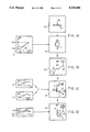
- FIG. 1 (A, B, C and D) is a diagram showing the various successive steps of the burnishing method of the invention
- FIG. 2 is a section through burnishing tooling having a removable disk and specially designed to implement the method of the invention.
- FIG. 3 shows apparatus for implementing the above-specified method, applied in this case to burnishing a wheel rim, which wheel may be made of a light alloy such as a magnesium or aluminum alloy, the apparatus including a moving tool carrier associated with a numerically controlled machine (not shown).
- the description begins with the various successive steps of the burnishing method of the invention, with the burnishing being intended to impart surface compression stresses to metal parts, which parts may optionally be bodies of revolution.
- the first step of the method begins with measuring the surface state of the region of the part that is to be burnished, as represented in block 10 which shows a part P whose surface state is measured (parameter Ra).
- This measurement of the surface state is fundamental because it makes it possible to select the functional width of the disk that is appropriate for obtaining optimum burnishing conditions for the part in question.
- such a measurement of surface state prior to burnishing constitutes an essential parameter in determining burnishing conditions.
- the surface state is traditionally identified by a parameter Ra having a dimension of length.
- the width of the disk to be used is determined from curves that are pre-established for each type of part to be burnished and for each type of material concerned.
- Block 21 thus illustrates a curve giving optimum values of disk width L for a given surface state Ra.
- the curve, referenced 25, relates to a particular part and to a particular material.
- the operator thus has a series of pre-established curves, which are preferably obtained using reject parts or raw parts having excess thickness and corresponding to the parts to be burnished. It is of interest to observe that the curve 25 is established for a predetermined range of values of the parameter Ra, between two limits Ra1 and Ra2.
- measuring the parameter Ra as represented by diagram block 10 makes it possible to deduce the optimum functional width L of the disk to be used as represented by block 21, which disk is then selected from the set available to the operator as represented by block 20 which shows a disk G of functional width L selected in this way.
- the steps of measuring the surface state and of selecting the width of the disk to be used for the burnishing constitute the first step a) of the burnishing method of the invention.
- the disk G selected in this way is installed on a tool carrier PO connected to a moving tailstock BM.
- the disk is at one end of an associated flexure bar BF whose other end is fixed to said tool carrier.
- This installation step is represented diagrammatically by block 30, and the corresponding tooling is described in greater detail below with reference to FIGS. 2 and 3.
- a step c) the disk G installed in this way is pressed against the part concerned P by exerting a predetermined force on the disk as a function of the desired surface compression stresses.
- This operation is represented by block 40, in which there can be seen the disk G being pressed against the part to be burnished P, and forming an angle A therewith.
- the flexure BF is caused to bend by displacement of the tool carrier PO connected to the moving tailstock BM which moves along a direction X that is essentially normal to the plane of the surface P.
- FIG. 1 shows a preferred method of selecting the predetermined force to be exerted on the disk G as a function of the desired surface compression stresses.
- curves 45 For each part to be burnished and for each corresponding material, the operator has two curves available, one of which curves 45 associates a parameter CSC corresponding to surface compression stresses with a parameter EG corresponding to forces exerted on the disk, said curve being shown diagrammatically in block 41.
- a curve 45 is pre-established for stress values going from 0 up to the plastification limit beyond which the material begins to crack (for an aluminum alloy, that corresponds to a value of about 400 MPa).
- curve 45 makes it immediately possible to determine the force to be exerted on the disk EG to obtain a given value of surface compression stresses.
- a second curve 46 shown in diagrammatic block 42, which relates the above-mentioned parameter EG to a parameter FBF relating to the deflection of the flexure bar at the disk.
- the curve 46 is essentially rectilinear since the flexure bar behaves like a spring, so its deflection is proportional to the force exerted.
- the operator can easily determine the corresponding deflection for the flexure bar, and can program the machine tool in such a manner that the tool carrier is displaced in the direction X (which is orthogonal to the plane of the surface to be burnished) until a desired value is obtained for the deflection of the flexure bar BF.
- at least one strain gauge is available on the flexure bar so as to obtain an instantaneous measurement of the deflection of said bar, such that the above-mentioned programming of tool carrier displacement can be performed very easily once the operator has entered the desired value of surface compression stresses into the machine.
- the step shown diagrammatically in block 40 may also include selecting the angle inclination A of the disk G as a function of the force EG to be exerted.
- the position of the disk G can be adjusted angularly: such angular adjustment may be the result of an additional degree of freedom for the moving tailstock BM, or it may result from a hinge on the tool carrier PO, or it may be the result of selecting the tooling to be mounted on the moving tailstock from a range having different angles of attack.
- the compliance can be adjusted by selecting a flexure bar BF whose characteristics are such that the bar has a determined deflection matching the value of FBF that corresponds to the force to be exerted on the disk G.
- the flexure bar BF must be removably mounted on the tool carrier PO so as to make it easy to remove and replace.
- This monitoring is represented by block 51 where there can be seen a curve 55 showing variations in the parameter EG as a function of time, the values of said parameter being required to remain within a predetermined range, between predetermined limit values EG1 and EG2. If the burnishing force leaves said range, then a stop instruction is automatically given to the machine tool, thus preventing any risk of drift in the surface compression stresses actually exerted on the part while it is being burnished.
- the tooling includes a tool carrier PO in which a flexure bar BF is engaged, preferably being secured by releasable means so as to make it possible to change the flexure bar.
- a tool carrier PO in which a flexure bar BF is engaged, preferably being secured by releasable means so as to make it possible to change the flexure bar.
- bolts 103 are shown for fixing the flexure bar BF on the tool carrier PO.
- the tool carrier may be a spring blade that is rectangular or otherwise, having a cross-section that is selected as a function of the desired second moment of area.
- the flexure bar BF is extended by an end shaft 104 on which the disk G is mounted by means of a ball bearing 109.
- the disk G is removably mounted on the shaft 104 so as to enable a disk of predetermined width L to be mounted on said shaft.
- the disk thus includes a central hub 106 engaged on the associated bearing 109, with axial fastening being provided firstly by a shoulder 110 on the hub 106 and secondly by an endplate 113 which is fixed by removable means such as bolts 105 to the hub of the disk.
- the bearing 109, and consequently the disk G, is held axially by a ball abutment 111 secured to the shaft 104, and at the end of said shaft by a fixing nut 112 or the like.
- the disk G is thus free to rotate about its axis 150, and it has a web 107 with an active edge referenced 108.
- the peripheral edge 108 is rounded so as to be semicircular in shape in this case, but it would naturally be possible to select other shapes, e.g. a shape that is elliptical or even angular. More generally, this shape can be optimized case by case as a function of the parts to be burnished and the materials concerned.
- Two strain gauges JE1 and JE2 are also shown stuck to the flexure bar BF and enabling the deflection and the compression of the flexure bar BF to be measured, thus making it possible to monitor the forces exerted during burnishing.
- FIG. 3 shows a part to be burnished P which is constituted in this case by the rim of a wheel, and reference PR designates the profile of the region to be burnished.
- the component members of the burnishing apparatus 100 as already described above can be seen, including a moving tailstock BM supporting the tool carrier PO via a member 101 which is represented in this case in the form of a bar.
- the connection 102 between the bar 101 and the tool carrier PO could optionally be hinged so as to make it possible to vary the angular inclination of the disk G relative to the part to be burnished, i.e.
- the part P is rotated about its axis YY, thereby causing the disk G which is pressed against it to rotate about its own axis 150.
- the displacements of the moving tailstock BM along the directions X and Y are programmed so that the disk G follows the profile PR of the part to be burnished, while maintaining the pressure with which said disk is applied at the desired value.
- FIG. 3 also shows the fixing bolts 103 associated with the flexure bar BF, with such bolts naturally constituting merely an example for making it clear that the flexure bar can be mounted on the tool carrier PC in removable manner so as to make it possible to install a flexure bar of predetermined resilience on said tool carrier.
- the value selected for the angle A will depend on the type of compliance that is desired: the angle A is chosen to be small if it is desired to give precedence to deflection of the flexure bar BF, or on the contrary it will be large (i.e. close to 90°) if it is desired to give precedence to compression of said flexure bar (in which case the effects of compliance are practically lost).
- a method of burnishing and apparatus for implementing said method are thus provided which make it possible to perform burnishing under optimum conditions for different types of part to be burnished and for different component materials.
- the preliminary adjustments are now considerably simplified and, in addition, any risk of exceeding the surface compression stresses is avoided.
- the burnishing method of the invention makes it possible to perform burnishing at all possible inclinations of the surfaces to be burnished (horizontal, vertical, or inclined). By monitoring the deflection and the compression of the flexure bar, it is possible to ensure that the burnishing forces remain within an appropriate predetermined range. In the event of excessive drift from the selected nominal value, a signal is automatically sent to the machine tool to cause it to stop, and this constitutes an advantageous security feature when the parts concerned are sophisticated in shape and expensive to manufacture.
- the burnishing method of the invention thus always make it possible to select a disk which enables the desired value of surface compression stresses to be obtained with great accuracy, while also improving the surface state compared with the state prior to burnishing.
Landscapes
- Engineering & Computer Science (AREA)
- Mechanical Engineering (AREA)
- Finish Polishing, Edge Sharpening, And Grinding By Specific Grinding Devices (AREA)
- Manufacturing Of Magnetic Record Carriers (AREA)
Abstract
Description
Claims (5)
Applications Claiming Priority (2)
| Application Number | Priority Date | Filing Date | Title |
|---|---|---|---|
| FR9201687 | 1992-02-14 | ||
| FR9201687A FR2687341B1 (en) | 1992-02-14 | 1992-02-14 | METHOD FOR GALETTING METAL PARTS, PARTICULARLY LIGHT ALLOY WHEELS, AND DEVICE FOR CARRYING OUT SAID METHOD. |
Publications (1)
| Publication Number | Publication Date |
|---|---|
| US5329684A true US5329684A (en) | 1994-07-19 |
Family
ID=9426652
Family Applications (1)
| Application Number | Title | Priority Date | Filing Date |
|---|---|---|---|
| US08/014,737 Expired - Lifetime US5329684A (en) | 1992-02-14 | 1993-02-08 | Method of burnishing metal parts, in particular light alloy wheels, and apparatus for implementing said method |
Country Status (3)
| Country | Link |
|---|---|
| US (1) | US5329684A (en) |
| EP (1) | EP0556102A1 (en) |
| FR (1) | FR2687341B1 (en) |
Cited By (15)
| Publication number | Priority date | Publication date | Assignee | Title |
|---|---|---|---|---|
| WO1998041360A1 (en) * | 1997-03-19 | 1998-09-24 | Hayes Wheels International, Inc. | Burnished vehicle wheel |
| US5826453A (en) * | 1996-12-05 | 1998-10-27 | Lambda Research, Inc. | Burnishing method and apparatus for providing a layer of compressive residual stress in the surface of a workpiece |
| US6415486B1 (en) | 2000-03-01 | 2002-07-09 | Surface Technology Holdings, Ltd. | Method and apparatus for providing a residual stress distribution in the surface of a part |
| US6540450B2 (en) | 2000-11-29 | 2003-04-01 | Hayes Lemmerz International, Inc. | Tool and process for finishing a vehicle wheel surface |
| US20030085257A1 (en) * | 2001-11-02 | 2003-05-08 | The Boeing Company | Apparatus and method for forming weld joints having compressive residual stress patterns |
| US6622570B1 (en) | 2000-03-01 | 2003-09-23 | Surface Technology Holdings Ltd. | Method for reducing tensile stress zones in the surface of a part |
| US20040170769A1 (en) * | 2000-11-08 | 2004-09-02 | Gatton Geoffrey L. | Tool and process for chrome plating a vehicle wheel surface |
| US20050120557A1 (en) * | 2000-11-08 | 2005-06-09 | Gatton Geoffrey L. | Process for copper free chrome plating of a vehicle wheel surface |
| US20090211367A1 (en) * | 2004-06-14 | 2009-08-27 | Prevey Paul S | Method and apparatus for sensing distortion |
| US20120274128A1 (en) * | 2004-04-23 | 2012-11-01 | Umberto Afeltra | Process for manufacturing a light alloy wheel rim and wheel rim resulting therefrom |
| US20170173759A1 (en) * | 2015-12-21 | 2017-06-22 | General Electric Company | Surface treatment of turbomachinery |
| US9879536B2 (en) | 2015-12-21 | 2018-01-30 | General Electric Company | Surface treatment of turbomachinery |
| US10610963B2 (en) | 2017-05-17 | 2020-04-07 | General Electric Company | Surface treatment of turbomachinery |
| US20210354263A1 (en) * | 2017-01-26 | 2021-11-18 | Howard Newman | Multiple smooth elements bonded to a ground; novel tools and methods for surface improvement of metals and other materials |
| CN116000787A (en) * | 2023-03-27 | 2023-04-25 | 陕西联信材料科技有限公司 | Automatic polishing robot for aviation aircraft blades |
Citations (6)
| Publication number | Priority date | Publication date | Assignee | Title |
|---|---|---|---|---|
| US2977669A (en) * | 1958-03-06 | 1961-04-04 | Bendix Corp | Apparatus for roll-burnishing aircraft wheels and the like |
| GB881229A (en) * | 1958-03-06 | 1961-11-01 | Bendix Corp | Apparatus for roll burnishing aircraft wheels and the like |
| US4747284A (en) * | 1986-08-05 | 1988-05-31 | Robert Hudson | Metal spinning machine carriage and process for the operation of a metal spinning machine |
| US4821388A (en) * | 1987-04-24 | 1989-04-18 | Topy Kogyo Kabushiki Kaisha | Method for processing a nut seat on a wheel |
| US4835826A (en) * | 1986-12-01 | 1989-06-06 | The B.F. Goodrich Company | Method of burnishing |
| EP0330734A2 (en) * | 1988-02-29 | 1989-09-06 | Wilhelm Hegenscheidt Gesellschaft mbH | Compacting tool |
-
1992
- 1992-02-14 FR FR9201687A patent/FR2687341B1/en not_active Expired - Lifetime
-
1993
- 1993-02-05 EP EP93400299A patent/EP0556102A1/en not_active Withdrawn
- 1993-02-08 US US08/014,737 patent/US5329684A/en not_active Expired - Lifetime
Patent Citations (6)
| Publication number | Priority date | Publication date | Assignee | Title |
|---|---|---|---|---|
| US2977669A (en) * | 1958-03-06 | 1961-04-04 | Bendix Corp | Apparatus for roll-burnishing aircraft wheels and the like |
| GB881229A (en) * | 1958-03-06 | 1961-11-01 | Bendix Corp | Apparatus for roll burnishing aircraft wheels and the like |
| US4747284A (en) * | 1986-08-05 | 1988-05-31 | Robert Hudson | Metal spinning machine carriage and process for the operation of a metal spinning machine |
| US4835826A (en) * | 1986-12-01 | 1989-06-06 | The B.F. Goodrich Company | Method of burnishing |
| US4821388A (en) * | 1987-04-24 | 1989-04-18 | Topy Kogyo Kabushiki Kaisha | Method for processing a nut seat on a wheel |
| EP0330734A2 (en) * | 1988-02-29 | 1989-09-06 | Wilhelm Hegenscheidt Gesellschaft mbH | Compacting tool |
Cited By (24)
| Publication number | Priority date | Publication date | Assignee | Title |
|---|---|---|---|---|
| US5826453A (en) * | 1996-12-05 | 1998-10-27 | Lambda Research, Inc. | Burnishing method and apparatus for providing a layer of compressive residual stress in the surface of a workpiece |
| WO1998041360A1 (en) * | 1997-03-19 | 1998-09-24 | Hayes Wheels International, Inc. | Burnished vehicle wheel |
| US6415486B1 (en) | 2000-03-01 | 2002-07-09 | Surface Technology Holdings, Ltd. | Method and apparatus for providing a residual stress distribution in the surface of a part |
| US6622570B1 (en) | 2000-03-01 | 2003-09-23 | Surface Technology Holdings Ltd. | Method for reducing tensile stress zones in the surface of a part |
| US20050120557A1 (en) * | 2000-11-08 | 2005-06-09 | Gatton Geoffrey L. | Process for copper free chrome plating of a vehicle wheel surface |
| US7140949B2 (en) | 2000-11-08 | 2006-11-28 | Hayes Lemmerz International, Inc. | Tool and process for chrome plating a vehicle wheel surface |
| US6997787B2 (en) | 2000-11-08 | 2006-02-14 | Hayes Lemmerz International, Inc. | Process for copper free chrome plating of a vehicle wheel surface |
| US20040170769A1 (en) * | 2000-11-08 | 2004-09-02 | Gatton Geoffrey L. | Tool and process for chrome plating a vehicle wheel surface |
| US6893330B2 (en) | 2000-11-08 | 2005-05-17 | Hayes Lemmerz International, Inc. | Tool and process for chrome plating a vehicle wheel surface |
| US6733366B2 (en) | 2000-11-29 | 2004-05-11 | Hayes Lemmerz International, Inc. | Tool and process for finishing a vehicle wheel surface |
| US6540450B2 (en) | 2000-11-29 | 2003-04-01 | Hayes Lemmerz International, Inc. | Tool and process for finishing a vehicle wheel surface |
| US6926970B2 (en) | 2001-11-02 | 2005-08-09 | The Boeing Company | Apparatus and method for forming weld joints having compressive residual stress patterns |
| US20030085257A1 (en) * | 2001-11-02 | 2003-05-08 | The Boeing Company | Apparatus and method for forming weld joints having compressive residual stress patterns |
| US20120274128A1 (en) * | 2004-04-23 | 2012-11-01 | Umberto Afeltra | Process for manufacturing a light alloy wheel rim and wheel rim resulting therefrom |
| US20090211367A1 (en) * | 2004-06-14 | 2009-08-27 | Prevey Paul S | Method and apparatus for sensing distortion |
| US8375805B2 (en) | 2004-06-14 | 2013-02-19 | Surface Technology Holdings, Ltd. | Method and apparatus for sensing distortion |
| US20170173759A1 (en) * | 2015-12-21 | 2017-06-22 | General Electric Company | Surface treatment of turbomachinery |
| US9879536B2 (en) | 2015-12-21 | 2018-01-30 | General Electric Company | Surface treatment of turbomachinery |
| US10384326B2 (en) * | 2015-12-21 | 2019-08-20 | General Electric Company | Surface treatment of turbomachinery |
| US11506058B2 (en) | 2015-12-21 | 2022-11-22 | General Electric Company | Turbomachine component with surface repair |
| US20210354263A1 (en) * | 2017-01-26 | 2021-11-18 | Howard Newman | Multiple smooth elements bonded to a ground; novel tools and methods for surface improvement of metals and other materials |
| US10610963B2 (en) | 2017-05-17 | 2020-04-07 | General Electric Company | Surface treatment of turbomachinery |
| CN116000787A (en) * | 2023-03-27 | 2023-04-25 | 陕西联信材料科技有限公司 | Automatic polishing robot for aviation aircraft blades |
| CN116000787B (en) * | 2023-03-27 | 2023-08-18 | 陕西联信材料科技有限公司 | Automatic polishing robot for aviation aircraft blades |
Also Published As
| Publication number | Publication date |
|---|---|
| FR2687341B1 (en) | 1995-09-01 |
| FR2687341A1 (en) | 1993-08-20 |
| EP0556102A1 (en) | 1993-08-18 |
Similar Documents
| Publication | Publication Date | Title |
|---|---|---|
| US5329684A (en) | Method of burnishing metal parts, in particular light alloy wheels, and apparatus for implementing said method | |
| US7360427B2 (en) | Coupling element with varying wall thickness for an ultrasound probe | |
| CA2648715C (en) | Surface treatment apparatus and method | |
| JP2768524B2 (en) | Micro finishing machine | |
| US6666061B2 (en) | Apparatus for deep rolling of recesses and radii of crankshaft journal bearings | |
| DE69635385T2 (en) | Method and apparatus for optical polishing | |
| US8161785B2 (en) | Circular-shaping device for a rotating part, especially an exhaust housing of a turbo engine | |
| US10786883B2 (en) | Deep rolling tool and method | |
| US7185521B2 (en) | Method and apparatus for process control of burnishing | |
| WO2004028739A1 (en) | Method and device for creating internal compression stresses within the surface of workpieces | |
| US6067879A (en) | Procedure and apparatus for straightening a circular-saw blade into a desired shape | |
| WO2011107598A2 (en) | Autocalibration | |
| EP1587649B1 (en) | Device for the high-precision machining of the surface of an object, especially for polishing and lapping semiconductor substrates | |
| US12066794B2 (en) | Device and method for testing a mechanical property of a timepiece shaft | |
| EP3338939A1 (en) | Deep rolling tool and method | |
| DE68919051T2 (en) | Trim head for the final production of composite panes. | |
| DE102005034258A1 (en) | Rotor or wheel with e.g. diamond coating for use as high-precision grinding tool, has eccentricity measurement system controlling inbuilt actuators assuring running truth | |
| US20250303519A1 (en) | Robotic deep rolling tool design for surface texturing to control friction and coating bonding | |
| EP4628257A2 (en) | Multi-axis deep rolling tool for hollow fan blade complex edge base enhancing corrosion restistance | |
| JP2834016B2 (en) | Whetstone with centering mechanism | |
| DE69421722T2 (en) | METHOD AND DEVICE FOR IMPROVING THE CONE SHAPE OF A CYLINDRICAL WORKPIECE | |
| WO2022228620A1 (en) | Device for holding a component | |
| SU1349827A1 (en) | Method and apparatus for setting up the straightening and untwisting machine | |
| DE19730402C2 (en) | Process for optimizing the wall thickness of machine or vehicle parts | |
| JPS58166132A (en) | Automatic adjusting device for thrust pre-pressure of universal joint |
Legal Events
| Date | Code | Title | Description |
|---|---|---|---|
| AS | Assignment |
Owner name: MESSIER-BUGATTI, FRANCE Free format text: ASSIGNMENT OF ASSIGNORS INTEREST.;ASSIGNORS:BUDET, PASCAL;FLICKER, PIERRE;KREMER, GUY;AND OTHERS;REEL/FRAME:006427/0427 Effective date: 19930125 |
|
| STCF | Information on status: patent grant |
Free format text: PATENTED CASE |
|
| FPAY | Fee payment |
Year of fee payment: 4 |
|
| FPAY | Fee payment |
Year of fee payment: 8 |
|
| REMI | Maintenance fee reminder mailed | ||
| FPAY | Fee payment |
Year of fee payment: 12 |
|
| SULP | Surcharge for late payment |
Year of fee payment: 11 |
|
| AS | Assignment |
Owner name: MESSIER-BUGATTI-DOWTY, FRANCE Free format text: CHANGE OF NAME;ASSIGNOR:MESSIER-BUGATTI;REEL/FRAME:027015/0397 Effective date: 20110430 |