US5321958A - Small-sized refrigerator - Google Patents
Small-sized refrigerator Download PDFInfo
- Publication number
- US5321958A US5321958A US07/980,473 US98047392A US5321958A US 5321958 A US5321958 A US 5321958A US 98047392 A US98047392 A US 98047392A US 5321958 A US5321958 A US 5321958A
- Authority
- US
- United States
- Prior art keywords
- cold air
- evaporator
- plate member
- air passage
- defrosted water
- Prior art date
- Legal status (The legal status is an assumption and is not a legal conclusion. Google has not performed a legal analysis and makes no representation as to the accuracy of the status listed.)
- Expired - Lifetime
Links
- XLYOFNOQVPJJNP-UHFFFAOYSA-N water Substances O XLYOFNOQVPJJNP-UHFFFAOYSA-N 0.000 claims abstract description 81
- 230000002265 prevention Effects 0.000 abstract description 9
- 238000010276 construction Methods 0.000 description 3
- 239000003507 refrigerant Substances 0.000 description 3
- 230000009471 action Effects 0.000 description 2
- 230000000694 effects Effects 0.000 description 2
- 230000002708 enhancing effect Effects 0.000 description 1
- 230000008014 freezing Effects 0.000 description 1
- 238000007710 freezing Methods 0.000 description 1
- 230000004048 modification Effects 0.000 description 1
- 238000012986 modification Methods 0.000 description 1
- 230000009467 reduction Effects 0.000 description 1
- 230000004044 response Effects 0.000 description 1
- 238000009827 uniform distribution Methods 0.000 description 1
Images


Classifications
-
- F—MECHANICAL ENGINEERING; LIGHTING; HEATING; WEAPONS; BLASTING
- F25—REFRIGERATION OR COOLING; COMBINED HEATING AND REFRIGERATION SYSTEMS; HEAT PUMP SYSTEMS; MANUFACTURE OR STORAGE OF ICE; LIQUEFACTION SOLIDIFICATION OF GASES
- F25D—REFRIGERATORS; COLD ROOMS; ICE-BOXES; COOLING OR FREEZING APPARATUS NOT OTHERWISE PROVIDED FOR
- F25D19/00—Arrangement or mounting of refrigeration units with respect to devices or objects to be refrigerated, e.g. infrared detectors
-
- F—MECHANICAL ENGINEERING; LIGHTING; HEATING; WEAPONS; BLASTING
- F25—REFRIGERATION OR COOLING; COMBINED HEATING AND REFRIGERATION SYSTEMS; HEAT PUMP SYSTEMS; MANUFACTURE OR STORAGE OF ICE; LIQUEFACTION SOLIDIFICATION OF GASES
- F25D—REFRIGERATORS; COLD ROOMS; ICE-BOXES; COOLING OR FREEZING APPARATUS NOT OTHERWISE PROVIDED FOR
- F25D21/00—Defrosting; Preventing frosting; Removing condensed or defrost water
- F25D21/14—Collecting or removing condensed and defrost water; Drip trays
-
- F—MECHANICAL ENGINEERING; LIGHTING; HEATING; WEAPONS; BLASTING
- F25—REFRIGERATION OR COOLING; COMBINED HEATING AND REFRIGERATION SYSTEMS; HEAT PUMP SYSTEMS; MANUFACTURE OR STORAGE OF ICE; LIQUEFACTION SOLIDIFICATION OF GASES
- F25D—REFRIGERATORS; COLD ROOMS; ICE-BOXES; COOLING OR FREEZING APPARATUS NOT OTHERWISE PROVIDED FOR
- F25D17/00—Arrangements for circulating cooling fluids; Arrangements for circulating gas, e.g. air, within refrigerated spaces
- F25D17/04—Arrangements for circulating cooling fluids; Arrangements for circulating gas, e.g. air, within refrigerated spaces for circulating air, e.g. by convection
-
- F—MECHANICAL ENGINEERING; LIGHTING; HEATING; WEAPONS; BLASTING
- F25—REFRIGERATION OR COOLING; COMBINED HEATING AND REFRIGERATION SYSTEMS; HEAT PUMP SYSTEMS; MANUFACTURE OR STORAGE OF ICE; LIQUEFACTION SOLIDIFICATION OF GASES
- F25D—REFRIGERATORS; COLD ROOMS; ICE-BOXES; COOLING OR FREEZING APPARATUS NOT OTHERWISE PROVIDED FOR
- F25D2317/00—Details or arrangements for circulating cooling fluids; Details or arrangements for circulating gas, e.g. air, within refrigerated spaces, not provided for in other groups of this subclass
- F25D2317/06—Details or arrangements for circulating cooling fluids; Details or arrangements for circulating gas, e.g. air, within refrigerated spaces, not provided for in other groups of this subclass with forced air circulation
- F25D2317/066—Details or arrangements for circulating cooling fluids; Details or arrangements for circulating gas, e.g. air, within refrigerated spaces, not provided for in other groups of this subclass with forced air circulation characterised by the air supply
- F25D2317/0665—Details or arrangements for circulating cooling fluids; Details or arrangements for circulating gas, e.g. air, within refrigerated spaces, not provided for in other groups of this subclass with forced air circulation characterised by the air supply from the top
-
- F—MECHANICAL ENGINEERING; LIGHTING; HEATING; WEAPONS; BLASTING
- F25—REFRIGERATION OR COOLING; COMBINED HEATING AND REFRIGERATION SYSTEMS; HEAT PUMP SYSTEMS; MANUFACTURE OR STORAGE OF ICE; LIQUEFACTION SOLIDIFICATION OF GASES
- F25D—REFRIGERATORS; COLD ROOMS; ICE-BOXES; COOLING OR FREEZING APPARATUS NOT OTHERWISE PROVIDED FOR
- F25D2321/00—Details or arrangements for defrosting; Preventing frosting; Removing condensed or defrost water, not provided for in other groups of this subclass
- F25D2321/14—Collecting condense or defrost water; Removing condense or defrost water
- F25D2321/144—Collecting condense or defrost water; Removing condense or defrost water characterised by the construction of drip water collection pans
- F25D2321/1441—Collecting condense or defrost water; Removing condense or defrost water characterised by the construction of drip water collection pans inside a refrigerator
Definitions
- This invention relates to a small-sized refrigerator, and more particularly a small-sized refrigerator having improved evaporator and defrosted water drain pan to allow smooth convection of cold air produced at the evaporator, resulting in more uniform distribution of a temperature in a refrigerating chamber and a reduction in power consumption.
- a small-sized refrigerator does not comprise divided freezing and refrigerating chambers, but only a refrigerating chamber, in which there are provided an evaporator and a defrosted water drain pan disposed below the evaporator to receive defrosted water dropping thereform.
- Such a small-sized refrigerator comprises, as shown in FIGS. 1 to 4 of the accompanying drawings, a body 21 having a refrigerating chamber 22 provided therein, an evaporator 23 disposed at the upper side of the refrigerating chamber, a defrosted water drain pan 24 of a tray shape mounted below the evaporator to prevent the defrosted water from dropping to the lower portion of the chamber, a plurality of vertically spaced shelves 25 disposed transversely below the drain pan to support foodstuffs, a door 26 mounted in the front of the body 21 to prevent the cold air in the refrigerating chamber from flowing out, a compressor 27 disposed outside of the lower portion of the body to feed a refrigerant to the evaporator 23, and a temperature sensor (including a temperature control function) 28 mounted in the refrigerating chamber to turn on and off the compressor 27 depending upon the temperature in the chamber.
- a temperature sensor including a temperature control function
- the foodstuffs put on the shelves 25 in the refrigerating chamber 22 can be refrigerated and freshly preserved by cold air circulating in the chamber through a natural convection phenomenon.
- the cold air is produced by the action of the refrigerant compressed by the energized compressor 27 and introduced into the evaporator 23, and distributed in the chamber through the natural convection.
- the temperature sensor 28 disposed in the chamber detects it and stops the operation of the compressor 27. Thereafter, when the temperature rises again above the set temperature, the operation of the compressor is resumed through the sensing operation of the temperature sensor.
- the defrosted water drain pan 24 is usually mounted below the evaporator 23.
- This prior small-sized refrigerator however has a drawback in that since the evaporator 23 for producing the cold air is of a L-shape and secured to the body 21 by means of fastening members 29 provided on the interior of the body, as shown in FIGS. 1 and 3, a cold air producing area is restricted to one side of the refrigerating chamber 22, so that there is a very excessive temperature difference between the side of the evaporator 23 and the area opposite to the side.
- a small-sized refrigerator comprising an evaporator being of a plate shape to provide an increased cold air producing area, and a defrosted water drain pan formed with cold air passage openings to allow smooth convection of the cold air in a refrigerating chamber, thereby enabling the temperature in the refrigerating chamber to drop promptly to a set temperature and temperature differences between the respective areas of the chamber to be minimized.
- a small-sized refrigerator comprising an evaporator of a plate shape mounted horizontally in a refrigerating chamber by means of an engaging protrusion formed on one side of a temperature sensor disposed at one side of the upper portion of the chamber, and a fastening member formed integrally with a body of the refrigerator at the opposite side of the chamber; and a defrosted water drain pan disposed below the evaporator and having a plurality of cold air passage openings formed therein to allow a smooth flow of cold air produced at the evaporator.
- FIG. 1 is a schematic view illustrating the structure of the essential parts of a prior are small-sized refrigerator
- FIG. 2 is a cross-sectional view taken along line 2--2 of FIG. 1;
- FIG. 3 is a perspective view of an evaporator used in the small-sized refrigerator of the prior art
- FIG. 4 is a perspective view of a defrosted water drain pan used in the prior art refrigerator
- FIG. 5 is a schematic view illustrating the structure of the essential parts of the small-sized refrigerator according to the present invention.
- FIG. 6 is a perspective view of an evaporator used in the refrigerator of the present invention.
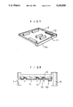
- FIG. 7 is a perspective view of one embodiment of a defrosted water drain pan used in the refrigerator of the present invention.
- FIG. 8 is a cross-sectional view of the drain pan of FIG. 7 in use state
- FIG. 9 is a perspective view of another embodiment of the defrosted water drain pan used in the refrigerator of the present invention.
- FIG. 10 is a cross-sectional view of the drain pan of FIG. 9 in the use state
- FIG. 11 is a cross-sectional view of still another embodiment of the defrosted water drain pan used in the refrigerator of the present invention.
- FIG. 12 is a perspective view showing an improved shelf used in the refrigerator of the present invention.
- the small-sized refrigerator of the present invention broadly comprises a body 1, a refrigerating chamber 2, an evaporator 3, a defrosted water drain pan 4, shelves 5, a door 6, a temperature sensor 7 and a compressor (not shown), similarly to a small-sized refrigerator of the prior art.
- the present invention resides in the improvements of the evaporator and the defrosted water drain pan. Therefore, the construction of the present invention will be described below in reference to the evaporator 3 and the defrosted water drain pan 4, and throughout the following description similar reference numerals refer to similar elements.
- FIG. 5 shows a schematic view of the structure of the essential parts of the small-sized refrigerator of the present invention
- FIG. 6 shows the evaporator used in the refrigerator of FIG. 5
- FIG. 7 shows the defrosted water drain pan of one embodiment used in the refrigerator of the present invention
- FIG. 8 shows in section the drain pan of FIG. 7 in the use state.
- the evaporator 3 is of a plate shape and mounted horizontally in the refrigerating chamber 2 by means of an engaging protrusion 8 formed on the lower end of one side of the temperature sensor 7, which is disposed at one side of the upper portion of the refrigerating chamber to control the temperature in the chamber, and a fastening member 9 formed integrally with the body 1 at the opposite side of the refrigerating chamber.
- the evaporator 3 is formed one side with a bent portion 3a, which is engaged with the fastening member 9 to prevent playing of the mounted evaporator.
- the defrosted water drain pan 4 detachably disposed below the evaporator 3 to receive the defrosted water dropping from the evaporator comprises a plurality of cold air passage openings 10 through which the cold air may pass, overflow prevention walls 11 formed along the periphery of each of the openings 10 to prevent the collected water in the drain pan from entering the openings, and inclined guide members 12 each connected on one side to one of the overflow prevention walls 11 with a predetermined degree of inclination to prevent the water dropping from the evaporator 3 to the cold air passage openings from passing downwardly through the openings.
- Each guide member 12 is arranged such that clearances for allowing cold air flow communication are defined between its free sides and the overflow prevention walls.
- the defrosted water drain pan 4 has a collection recess 4a formed at its front portion so as to store the defrosted water. Since the collection recess 4a is formed to protrude downwardly, it also serves as a handle when the drain pan is taken out of the refrigerator.
- the cold air is produced by the action of the refrigerant compressed in the compressor and passing through the evaporator 3 in a conventional manner.
- the evaporator is of a plate shape and mounted horizontally by means of the engaging protrusion 8 of the temperature sensor 7 disposed at one side of the upper portion of the refrigerating chamber 2, and the fastening member 9 formed integrally with the body 1, as shown in FIG. 5, an increased cold air producing area is provided, thereby enhancing the refrigerating capacity and greatly reducing the temperature variation at the upper portion of the refrigerating chamber.
- the cold air produced at the evaporator and circulating in the refrigerating chamber through the natural convection may pass through the cold air passage openings 10 formed in the defrosted water drain pan 4, smooth circulation of the cold air may be achieved.
- the function of the defrosted water drain pan 4 disposed below the evaporator 3 is to prevent the defrosted water dropping from the evaporator during operation of the refrigerator from falling to the lower portion of the refrigerating chamber. Therefore, the water dropping from the evaporator remains collected in the drain pan without entering the cold air passage openings 10 by virtue of the overflow prevention walls 11 formed around the openings.
- the water drips dropping directly toward the openings 10 are intercepted by the guide members 12 formed integrally with one of the overflow prevention walls 11 to cover the openings, and then flow down guided by the inclined guide members 12 to be collected in the drain pan 4 without falling to the lower portion of the refrigerating chamber through the openings.
- the drain pan 4 When the drain pan 4 has been filled with the defrosted water up to a predetermined level, i.e., to the extent that the water does not overflow the overflow prevention walls 11 of the cold air passage openings 10, the drain pan may be removed from the refrigerating chamber 2 to empty out the water from the pan, and then put again in the chamber.
- the evaporator 3 has an increased cold air producing area and the cold air produced at the evaporator may smoothly circulate in the refrigerating chamber through the cold air passage openings 10 of the defrosted water drain pan 4, the temperature differences between the respective areas of the chamber may be minimized and the average temperature in the chamber may be achieved and maintained in a short time. As a result, an operating rate of the compressor may be lowered, thereby reducing power comsumption.
- FIG. 9 and 10 show another embodiment of the defrosted water drain pan used in the refrigerator of the present invention.
- the defrosted water drain pan 34 of this embodiment has a plurality of cold air passage openings 10 formed in pairs and a plurality of defrosted water drip intercepting members 20 detachably disposed thereon one for a pair of the cold air passage openings 10.
- Each of the defrosted water drip intercepting members 20 comprises a wing plate 13 of a roof shape having a pair of inclined portions and a central plane portion between the inclined portions, a pair of supports 14 depending downwardly from the lower surface of the central portion of the wing plate 13, and a plurality of through holes 15 formed in the central portion of the wing plate 13 and the supports 14.
- the cold air produced at the evaporator 3 passes through the through holes 15 of the defrosted water drip intercepting members 20 and the cold air passage openings 10 of the defrosted water drain pan 34, thereby smoothly circulating in the refrigerating chamber, while the defrosted water dropping from the evaporator is collected in the defrosted water drain pan 34. At this time, the water drips dropping directly to the cold air passage openings 10 flow down guided by the inclined portions of the wing plate 13, and then are collected in the drain pan 34.
- This embodiment also has the same effects as those of the previous embodiment.
- FIG. 11 shows in section still another embodiment of the defrosted water drain pan mounted in the refrigerator of the present invention.
- the drain pan 44 of this embodiment comprises a hollow container having closed sides and upper and lower plates formed with a plurality of cold air passage openings 10. The openings are arranged such that the openings of the upper plate come out of registry with those of the lower plate. With this arrangement, the defrosted water produced at the evaporator 3 passes through the cold air passage openings of the upper and lower plates of the defrosted water drain pan 44 in the direction shown by the arrows, thereby smoothly circulating in the refrigerating chamber, while the water dropping from the evaporator is collected in the upper plate of the drain pan 44.
- FIG. 12 shows an improved shelf according to another feature of the present invention.
- the shelf 55 comprises a water drip tray portion 56 provided at its front portion.
- the drip tray portion is of a hollow container shape and includes an upper plate being a part of the main plate of the shelf and formed with a plurality of through holes 57 through which the cold air and the water drips may pass, and a lower plate serving as a drip tray and provided with a plurality of cold air passages 58 which are formed in registry with the holes of the upper plate.
- the lower plate is narrower in width than the upper plate such that the drip tray portion has flanges by which the shelf may be supported on the inner walls of the body of the refrigerator.
- Each cold air passage 58 of the lower plate comprises an opening through which the cold air may pass, overflow prevention walls formed along the periphery of the opening and an inclined guide member, which are similar to the cold air passage opening 10, the overflow prevention walls 11 and the guide member 12 of the defrosted water drain pan 4 shown in FIG. 7, respectively.
- This shelf acts to allow the smooth convection of the cold air, while preventing the water drips from dropping to the lower portion of the refrigerating chamber.
Landscapes
- Engineering & Computer Science (AREA)
- Chemical & Material Sciences (AREA)
- Combustion & Propulsion (AREA)
- Physics & Mathematics (AREA)
- Mechanical Engineering (AREA)
- Thermal Sciences (AREA)
- General Engineering & Computer Science (AREA)
- Removal Of Water From Condensation And Defrosting (AREA)
Abstract
This invention relates to a small-sized refrigerator comprising an evaporator being of a plate shape to provide an increased cold air producing area, and a defrosted water drain pan formed with a plurality of cold air passage openings to allow smooth convention of cold air in a refrigerating chamber, thereby enabling a proper temperature in the chamber to be achieved promptly and the temperature differences between the respective areas of the chamber to be minimized. To this end, the evaporator of a plate shape is mounted horizontally at the upper portion of the refrigerating chamber, and the defrosted water drain pan having a plurality of the cold air passage openings, overflow prevention walls and guide members for preventing defrosted water from passing through the openings is detachably disposed below the evaporator to collect the defrosted water dropping from the evaporator.
Description
1. Field of the Invention
This invention relates to a small-sized refrigerator, and more particularly a small-sized refrigerator having improved evaporator and defrosted water drain pan to allow smooth convection of cold air produced at the evaporator, resulting in more uniform distribution of a temperature in a refrigerating chamber and a reduction in power consumption.
2. Description of the Prior Art
Generally, a small-sized refrigerator does not comprise divided freezing and refrigerating chambers, but only a refrigerating chamber, in which there are provided an evaporator and a defrosted water drain pan disposed below the evaporator to receive defrosted water dropping thereform.
Such a small-sized refrigerator according to the prior art comprises, as shown in FIGS. 1 to 4 of the accompanying drawings, a body 21 having a refrigerating chamber 22 provided therein, an evaporator 23 disposed at the upper side of the refrigerating chamber, a defrosted water drain pan 24 of a tray shape mounted below the evaporator to prevent the defrosted water from dropping to the lower portion of the chamber, a plurality of vertically spaced shelves 25 disposed transversely below the drain pan to support foodstuffs, a door 26 mounted in the front of the body 21 to prevent the cold air in the refrigerating chamber from flowing out, a compressor 27 disposed outside of the lower portion of the body to feed a refrigerant to the evaporator 23, and a temperature sensor (including a temperature control function) 28 mounted in the refrigerating chamber to turn on and off the compressor 27 depending upon the temperature in the chamber.
With this construction, the foodstuffs put on the shelves 25 in the refrigerating chamber 22 can be refrigerated and freshly preserved by cold air circulating in the chamber through a natural convection phenomenon. The cold air is produced by the action of the refrigerant compressed by the energized compressor 27 and introduced into the evaporator 23, and distributed in the chamber through the natural convection. At this time, when the temperature in the refrigerating chamber drops below a set temperature, the temperature sensor 28 disposed in the chamber detects it and stops the operation of the compressor 27. Thereafter, when the temperature rises again above the set temperature, the operation of the compressor is resumed through the sensing operation of the temperature sensor.
The foregoing describes one cycle of the operation of the refrigerator. Therefore, as long as the electric power is supplied to the refrigerator, "ON" and "OFF" of the compressor 27 is continually repeated in response to the sensing operation of the temperature sensor 28 depending upon temperature variations from the set temperature.
During the operation of the refrigerator, ice is usually formed on the outer surface of the evaporator 23 due to the cold air flow produced around the evaporator. With continued use of the refrigerator, the ice is excessively formed on the evaporator, to thereby reduce the refrigerating capacity of the refrigerator, so that there is a need to melt the ice by temporarily turning off the refrigerator. Therefore, in order to prevent the water produced by the deicing operation from dropping downwardly to the lower portion of the refrigerating chamber, the defrosted water drain pan 24 is usually mounted below the evaporator 23.
This prior small-sized refrigerator however has a drawback in that since the evaporator 23 for producing the cold air is of a L-shape and secured to the body 21 by means of fastening members 29 provided on the interior of the body, as shown in FIGS. 1 and 3, a cold air producing area is restricted to one side of the refrigerating chamber 22, so that there is a very excessive temperature difference between the side of the evaporator 23 and the area opposite to the side. Further, in the prior refrigerator, since the naturally convective flow of the cold air originating from the evaporator is intercepted by the defrosted water drain pan 24 disposed below the evaporator and passes through only the gap between the body 21 and the drain pan, smooth convection of the cold air may not be achieved and a long operating time of the compressor 27 is required to maintain the average temperature (usually 3° C.) in the refrigerating chamber, so that power consumption is increased.
With the foregoing drawbacks of the prior art in view, it is an object of the present invention to provide a small-sized refrigerator comprising an evaporator being of a plate shape to provide an increased cold air producing area, and a defrosted water drain pan formed with cold air passage openings to allow smooth convection of the cold air in a refrigerating chamber, thereby enabling the temperature in the refrigerating chamber to drop promptly to a set temperature and temperature differences between the respective areas of the chamber to be minimized.
To achieve the above object, there is provided according to the present invention a small-sized refrigerator comprising an evaporator of a plate shape mounted horizontally in a refrigerating chamber by means of an engaging protrusion formed on one side of a temperature sensor disposed at one side of the upper portion of the chamber, and a fastening member formed integrally with a body of the refrigerator at the opposite side of the chamber; and a defrosted water drain pan disposed below the evaporator and having a plurality of cold air passage openings formed therein to allow a smooth flow of cold air produced at the evaporator.
In the accompanying drawings:
FIG. 1 is a schematic view illustrating the structure of the essential parts of a prior are small-sized refrigerator;
FIG. 2 is a cross-sectional view taken along line 2--2 of FIG. 1;
FIG. 3 is a perspective view of an evaporator used in the small-sized refrigerator of the prior art;
FIG. 4 is a perspective view of a defrosted water drain pan used in the prior art refrigerator;
FIG. 5 is a schematic view illustrating the structure of the essential parts of the small-sized refrigerator according to the present invention;
FIG. 6 is a perspective view of an evaporator used in the refrigerator of the present invention;
FIG. 7 is a perspective view of one embodiment of a defrosted water drain pan used in the refrigerator of the present invention;
FIG. 8 is a cross-sectional view of the drain pan of FIG. 7 in use state;
FIG. 9 is a perspective view of another embodiment of the defrosted water drain pan used in the refrigerator of the present invention;
FIG. 10 is a cross-sectional view of the drain pan of FIG. 9 in the use state;
FIG. 11 is a cross-sectional view of still another embodiment of the defrosted water drain pan used in the refrigerator of the present invention; and
FIG. 12 is a perspective view showing an improved shelf used in the refrigerator of the present invention.
The invention will now be described in more detail, by way of example, with reference to FIGS. 5 to 11 of the accompanying drawings.
The small-sized refrigerator of the present invention broadly comprises a body 1, a refrigerating chamber 2, an evaporator 3, a defrosted water drain pan 4, shelves 5, a door 6, a temperature sensor 7 and a compressor (not shown), similarly to a small-sized refrigerator of the prior art. The present invention resides in the improvements of the evaporator and the defrosted water drain pan. Therefore, the construction of the present invention will be described below in reference to the evaporator 3 and the defrosted water drain pan 4, and throughout the following description similar reference numerals refer to similar elements.
Reference is first made to FIGS. 5 to 8. FIG. 5 shows a schematic view of the structure of the essential parts of the small-sized refrigerator of the present invention; FIG. 6 shows the evaporator used in the refrigerator of FIG. 5; FIG. 7 shows the defrosted water drain pan of one embodiment used in the refrigerator of the present invention; and FIG. 8 shows in section the drain pan of FIG. 7 in the use state.
According to the present invention, the evaporator 3 is of a plate shape and mounted horizontally in the refrigerating chamber 2 by means of an engaging protrusion 8 formed on the lower end of one side of the temperature sensor 7, which is disposed at one side of the upper portion of the refrigerating chamber to control the temperature in the chamber, and a fastening member 9 formed integrally with the body 1 at the opposite side of the refrigerating chamber. Preferably, the evaporator 3 is formed one side with a bent portion 3a, which is engaged with the fastening member 9 to prevent playing of the mounted evaporator.
The defrosted water drain pan 4 detachably disposed below the evaporator 3 to receive the defrosted water dropping from the evaporator comprises a plurality of cold air passage openings 10 through which the cold air may pass, overflow prevention walls 11 formed along the periphery of each of the openings 10 to prevent the collected water in the drain pan from entering the openings, and inclined guide members 12 each connected on one side to one of the overflow prevention walls 11 with a predetermined degree of inclination to prevent the water dropping from the evaporator 3 to the cold air passage openings from passing downwardly through the openings. Each guide member 12 is arranged such that clearances for allowing cold air flow communication are defined between its free sides and the overflow prevention walls.
Further, the defrosted water drain pan 4 has a collection recess 4a formed at its front portion so as to store the defrosted water. Since the collection recess 4a is formed to protrude downwardly, it also serves as a handle when the drain pan is taken out of the refrigerator.
The cold air is produced by the action of the refrigerant compressed in the compressor and passing through the evaporator 3 in a conventional manner. In the present invention, since the evaporator is of a plate shape and mounted horizontally by means of the engaging protrusion 8 of the temperature sensor 7 disposed at one side of the upper portion of the refrigerating chamber 2, and the fastening member 9 formed integrally with the body 1, as shown in FIG. 5, an increased cold air producing area is provided, thereby enhancing the refrigerating capacity and greatly reducing the temperature variation at the upper portion of the refrigerating chamber. Furthermore, since the cold air produced at the evaporator and circulating in the refrigerating chamber through the natural convection may pass through the cold air passage openings 10 formed in the defrosted water drain pan 4, smooth circulation of the cold air may be achieved.
The function of the defrosted water drain pan 4 disposed below the evaporator 3 is to prevent the defrosted water dropping from the evaporator during operation of the refrigerator from falling to the lower portion of the refrigerating chamber. Therefore, the water dropping from the evaporator remains collected in the drain pan without entering the cold air passage openings 10 by virtue of the overflow prevention walls 11 formed around the openings. The water drips dropping directly toward the openings 10 are intercepted by the guide members 12 formed integrally with one of the overflow prevention walls 11 to cover the openings, and then flow down guided by the inclined guide members 12 to be collected in the drain pan 4 without falling to the lower portion of the refrigerating chamber through the openings.
When the drain pan 4 has been filled with the defrosted water up to a predetermined level, i.e., to the extent that the water does not overflow the overflow prevention walls 11 of the cold air passage openings 10, the drain pan may be removed from the refrigerating chamber 2 to empty out the water from the pan, and then put again in the chamber.
As discussed above, since the evaporator 3 has an increased cold air producing area and the cold air produced at the evaporator may smoothly circulate in the refrigerating chamber through the cold air passage openings 10 of the defrosted water drain pan 4, the temperature differences between the respective areas of the chamber may be minimized and the average temperature in the chamber may be achieved and maintained in a short time. As a result, an operating rate of the compressor may be lowered, thereby reducing power comsumption.
FIG. 9 and 10 show another embodiment of the defrosted water drain pan used in the refrigerator of the present invention. The defrosted water drain pan 34 of this embodiment has a plurality of cold air passage openings 10 formed in pairs and a plurality of defrosted water drip intercepting members 20 detachably disposed thereon one for a pair of the cold air passage openings 10. Each of the defrosted water drip intercepting members 20 comprises a wing plate 13 of a roof shape having a pair of inclined portions and a central plane portion between the inclined portions, a pair of supports 14 depending downwardly from the lower surface of the central portion of the wing plate 13, and a plurality of through holes 15 formed in the central portion of the wing plate 13 and the supports 14.
With this construction, the cold air produced at the evaporator 3 passes through the through holes 15 of the defrosted water drip intercepting members 20 and the cold air passage openings 10 of the defrosted water drain pan 34, thereby smoothly circulating in the refrigerating chamber, while the defrosted water dropping from the evaporator is collected in the defrosted water drain pan 34. At this time, the water drips dropping directly to the cold air passage openings 10 flow down guided by the inclined portions of the wing plate 13, and then are collected in the drain pan 34. This embodiment also has the same effects as those of the previous embodiment.
FIG. 11 shows in section still another embodiment of the defrosted water drain pan mounted in the refrigerator of the present invention. The drain pan 44 of this embodiment comprises a hollow container having closed sides and upper and lower plates formed with a plurality of cold air passage openings 10. The openings are arranged such that the openings of the upper plate come out of registry with those of the lower plate. With this arrangement, the defrosted water produced at the evaporator 3 passes through the cold air passage openings of the upper and lower plates of the defrosted water drain pan 44 in the direction shown by the arrows, thereby smoothly circulating in the refrigerating chamber, while the water dropping from the evaporator is collected in the upper plate of the drain pan 44. The water drips falling directly to the cold air passage openings 10 of the upper plate of the drain pan are collected on the lower plate of the drain pan. When the upper plate is full of the water overflowing water falls through the openings 10 of the upper plate to the lower plate of the drain pan 44 to be collected thereon. This embodiment also has the same effects as those of the embodiments described above.
FIG. 12 shows an improved shelf according to another feature of the present invention. The shelf 55 comprises a water drip tray portion 56 provided at its front portion. The drip tray portion is of a hollow container shape and includes an upper plate being a part of the main plate of the shelf and formed with a plurality of through holes 57 through which the cold air and the water drips may pass, and a lower plate serving as a drip tray and provided with a plurality of cold air passages 58 which are formed in registry with the holes of the upper plate. The lower plate is narrower in width than the upper plate such that the drip tray portion has flanges by which the shelf may be supported on the inner walls of the body of the refrigerator. Each cold air passage 58 of the lower plate comprises an opening through which the cold air may pass, overflow prevention walls formed along the periphery of the opening and an inclined guide member, which are similar to the cold air passage opening 10, the overflow prevention walls 11 and the guide member 12 of the defrosted water drain pan 4 shown in FIG. 7, respectively. This shelf acts to allow the smooth convection of the cold air, while preventing the water drips from dropping to the lower portion of the refrigerating chamber.
While the invention has been shown and described with particular reference to various embodiments thereof, it will be understood that variations and modifications in form and detail may be made therein without departing from the spirit and scope of the invention defined in the appended claims.
Claims (13)
1. A small sized refrigerator comprising:
an evaporator mounted horizontally at the upper portion of a refrigerating chamber for producing cold air;
a defrosted water drain pan disposed below said evaporator for collecting defrosted water dropping from said evaporator, said defrost water drain pan comprising a plurality of air passage means for allowing said cold air to pass through said defrosted water drain pan within said refrigerating chamber;
shelves disposed below said drain pan for supporting foodstuffs;
temperature sensing means for sensing a temperature in said refrigerating chamber; and
a door.
2. A small-sized refrigerator as claimed in claim 1, in which said evaporator is mounted by means of an engaging protrusion formed on the lower end of one side of said temperature sensing means, and a fastening member provided on the side of said refrigerating chamber opposite to said temperature sensing means.
3. A small-sized refrigerator as claimed in claim 1, in which said defrosted water drain pan comprises:
a plate member for collecting the defrosted water dropping from said evaporator;
a plurality of cold air passage means formed in pairs in said plate member to permit the cold air originating from said evaporator to be circulated in said refrigerating chamber through them;
guide means formed integrally with said plate member to prevent the collected water on said plate member from entering said cold air passage means; and
a plurality of defrosted water drip interception means disposed above said cold air passage means, one for a pair of the passage means, to prevent the defrosted water dropping from said evaporator from falling directly to the lower portion of said chamber through said cold air passage means.
4. A small-sized refrigerator as claimed in claim 3, in which each of said defrosted water drip intercepting means comprises:
a wing member for preventing the defrosted water from falling directly to the lower portion of said chamber through a pair of said cold air passage means;
through holes formed in the central portion of said wing member; and
support members provided at the underside of said wing member and detachably engaged with said guide means.
5. A small-sized refrigerator as claimed in claim 1, in which said defrosted water drain pan comprises:
a first plate member for collecting the defrosted water dropping from said evaporator;
a second plate member disposed below said first plate member to collect the overflowing water dropping from said first plate member; and
cold air passage means formed in said first and second plate members to permit the cold air originating from said evaporator to be circulated in said chamber through them.
6. A small-sized refrigerator as claimed in claim 5, in which said cold air passage means are arranged such that the cold air passage means of said first plate member come out of registry with those of said second plate member.
7. A small-sized refrigerator as claimed in claim 1, in which each of said shelves comprises a panel having a plurality of first cold air passage means formed therein to allow smooth convection of the cold air; and a drip tray disposed below said panel to collect the water dropping from said panel and formed with a plurality of second cold air passage means for permitting the cold air to be circulated in said refrigerating chamber through them.
8. A small-sized refrigerator as claimed in claim 7, in which said drip tray comprises a plate member disposed below a portion of the shelf; and guide members provided on said plate member to prevent the collected water on said plate member from falling down through said second cold air passage means.
9. A small-sized refrigerator as claimed in claim 8, in which said drip tray further comprises second guide members provided to prevent the water dropping from said first cold air passage means of said panel from falling down directly through said second cold air passage means.
10. A small sized refrigerator comprising:
an evaporator for producing cold air in a refrigerating chamber;
a defrosted water drain pan disposed below said evaporator for collecting defrosted water dropping from said evaporator, while allowing said cold air to pass therethrough into said refrigerating chamber;
shelves disposed below said drain pan for supporting foodstuffs;
temperature sensing means for sensing a temperature in said refrigerating chamber; and
a door;
said evaporator mounted horizontally at the upper portion of said refrigerating chamber by means of an engaging protrusion formed on the lower end of one side of said temperature sensing means and a fastening member provided on the side of said refrigerating chamber opposite to said temperature sensing means.
11. A small-sized refrigerator as claimed in claim 10, in which said evaporator is formed one side with a bent portion, which is engaged with said fastening member to prevent playing of the mounted evaporator.
12. A small-sized refrigerator as claimed in claim 10, in which said defrosted water drain pan comprises a plate member for collecting the defrosted water dropping from said evaporator;
a plurality of cold air passage means formed in said plate member to permit the cold air originating from said evaporator to be circulated in said refrigerating chamber through them;
first guide means provided on said plate member to prevent the defrosted water dropping from said evaporator from falling directly to the lower portion of said chamber through said cold air passage means; and
second guide means provided on said plate member to prevent the water collected on said plate member from entering said cold air passage means.
13. A small-sized refrigerator as claimed in claim 12, in which said plate member comprises storage means for storing the defrosted water collected on said plate member, the storage means also serving as a handle facilitating mounting and removal of said drain pan.
Applications Claiming Priority (2)
| Application Number | Priority Date | Filing Date | Title |
|---|---|---|---|
| KR1019910021963A KR920012864A (en) | 1990-12-03 | 1991-12-02 | Mini fridge |
| KR21963/1991 | 1991-12-02 |
Publications (1)
| Publication Number | Publication Date |
|---|---|
| US5321958A true US5321958A (en) | 1994-06-21 |
Family
ID=19324004
Family Applications (1)
| Application Number | Title | Priority Date | Filing Date |
|---|---|---|---|
| US07/980,473 Expired - Lifetime US5321958A (en) | 1991-12-02 | 1992-11-23 | Small-sized refrigerator |
Country Status (3)
| Country | Link |
|---|---|
| US (1) | US5321958A (en) |
| KR (1) | KR920012864A (en) |
| AU (1) | AU662023B2 (en) |
Cited By (6)
| Publication number | Priority date | Publication date | Assignee | Title |
|---|---|---|---|---|
| GB2300250A (en) * | 1995-04-29 | 1996-10-30 | E H Booth & Co Limited | Refrigerated display cases |
| US5669358A (en) * | 1995-03-27 | 1997-09-23 | Sanshin Kogyo Kabushiki Kaisha | Engine fuel supply system |
| EP0823602A1 (en) * | 1996-07-11 | 1998-02-11 | Norcold, Inc. | Vented drip tray for gas absorption refrigerators |
| US20100192609A1 (en) * | 2009-01-30 | 2010-08-05 | Lg Electronics Inc. | Refrigerator related technology |
| CN108698482A (en) * | 2016-02-24 | 2018-10-23 | 株式会社电装 | Vehicular air-conditioning unit |
| CN110160303A (en) * | 2018-02-16 | 2019-08-23 | 东芝生活电器株式会社 | Refrigerator |
Citations (1)
| Publication number | Priority date | Publication date | Assignee | Title |
|---|---|---|---|---|
| US3280583A (en) * | 1965-05-12 | 1966-10-25 | Gen Electric | Combination refrigerator |
-
1991
- 1991-12-02 KR KR1019910021963A patent/KR920012864A/en not_active Ceased
-
1992
- 1992-11-20 AU AU28492/92A patent/AU662023B2/en not_active Ceased
- 1992-11-23 US US07/980,473 patent/US5321958A/en not_active Expired - Lifetime
Patent Citations (1)
| Publication number | Priority date | Publication date | Assignee | Title |
|---|---|---|---|---|
| US3280583A (en) * | 1965-05-12 | 1966-10-25 | Gen Electric | Combination refrigerator |
Cited By (11)
| Publication number | Priority date | Publication date | Assignee | Title |
|---|---|---|---|---|
| US5669358A (en) * | 1995-03-27 | 1997-09-23 | Sanshin Kogyo Kabushiki Kaisha | Engine fuel supply system |
| GB2300250A (en) * | 1995-04-29 | 1996-10-30 | E H Booth & Co Limited | Refrigerated display cases |
| EP0823602A1 (en) * | 1996-07-11 | 1998-02-11 | Norcold, Inc. | Vented drip tray for gas absorption refrigerators |
| US20100192609A1 (en) * | 2009-01-30 | 2010-08-05 | Lg Electronics Inc. | Refrigerator related technology |
| US8584482B2 (en) * | 2009-01-30 | 2013-11-19 | Lg Electronics Inc. | Refrigerator related technology |
| CN108698482A (en) * | 2016-02-24 | 2018-10-23 | 株式会社电装 | Vehicular air-conditioning unit |
| US20190047351A1 (en) * | 2016-02-24 | 2019-02-14 | Denso Corporation | Air conditioning unit for vehicle |
| US10800226B2 (en) * | 2016-02-24 | 2020-10-13 | Denso Corporation | Air conditioning unit for vehicle having air conditioning case with backflow prevention rib |
| CN108698482B (en) * | 2016-02-24 | 2021-11-09 | 株式会社电装 | Air conditioning unit for vehicle |
| DE112017000982B4 (en) | 2016-02-24 | 2024-12-24 | Denso Corporation | AIR CONDITIONING UNIT FOR A VEHICLE |
| CN110160303A (en) * | 2018-02-16 | 2019-08-23 | 东芝生活电器株式会社 | Refrigerator |
Also Published As
| Publication number | Publication date |
|---|---|
| KR920012864A (en) | 1992-07-27 |
| AU2849292A (en) | 1993-06-03 |
| AU662023B2 (en) | 1995-08-17 |
Similar Documents
| Publication | Publication Date | Title |
|---|---|---|
| US5388427A (en) | Refrigerator with kimchi compartment | |
| US5784896A (en) | Freezer or refrigerator construction suitable for food service use | |
| EP0345437A2 (en) | Refrigerating apparatus with at least one compartment at even temperature and high relative humidity | |
| US2967404A (en) | Refrigerated display case | |
| US4353223A (en) | Refrigerator with a large refrigeration chamber cooled by natural convection | |
| US8966929B2 (en) | Cooled air recirculation in a refrigerator | |
| JP2601057B2 (en) | Freezer refrigerator | |
| US5321958A (en) | Small-sized refrigerator | |
| US3310957A (en) | Keeping insulation dry | |
| EP0126521B1 (en) | Refrigerator | |
| KR100259920B1 (en) | Apparatus for supplying cold air in refrigerator | |
| US5706673A (en) | Freezing compartment air flow system of refrigerator | |
| JP4095164B2 (en) | Indirect cooling refrigerator | |
| US7559211B2 (en) | Air tower with heat trap compartment for top mount freezer refrigerator | |
| US4150550A (en) | Self defrosting refrigerated display case | |
| US2175498A (en) | Refrigerator | |
| JP2654174B2 (en) | Cold storage | |
| KR100412412B1 (en) | Structure for supply drawer type storeroom of Kim-Chi storage with cool air | |
| KR0155971B1 (en) | Evaporator cover of refrigerators | |
| JPH029350Y2 (en) | ||
| KR100245570B1 (en) | Cooling air circulation device of a refrigerator | |
| JP3128420B2 (en) | High humidity low temperature storage | |
| JPH08210759A (en) | Cooling/storing apparatus | |
| JP2771640B2 (en) | Dew receiving device for high humidity and low temperature storage | |
| JPH07122544B2 (en) | High humidity low temperature storage |
Legal Events
| Date | Code | Title | Description |
|---|---|---|---|
| AS | Assignment |
Owner name: GOLD STAR CO., LTD., KOREA, REPUBLIC OF Free format text: ASSIGNMENT OF ASSIGNORS INTEREST.;ASSIGNOR:KIM, SEOK RO;REEL/FRAME:006399/0303 Effective date: 19921205 |
|
| STCF | Information on status: patent grant |
Free format text: PATENTED CASE |
|
| FEPP | Fee payment procedure |
Free format text: PAYOR NUMBER ASSIGNED (ORIGINAL EVENT CODE: ASPN); ENTITY STATUS OF PATENT OWNER: LARGE ENTITY |
|
| FPAY | Fee payment |
Year of fee payment: 4 |
|
| FPAY | Fee payment |
Year of fee payment: 8 |
|
| FPAY | Fee payment |
Year of fee payment: 12 |