US531931A - Leveling-instrument - Google Patents
Leveling-instrument Download PDFInfo
- Publication number
- US531931A US531931A US531931DA US531931A US 531931 A US531931 A US 531931A US 531931D A US531931D A US 531931DA US 531931 A US531931 A US 531931A
- Authority
- US
- United States
- Prior art keywords
- bar
- arm
- instrument
- level
- pointer
- Prior art date
- Legal status (The legal status is an assumption and is not a legal conclusion. Google has not performed a legal analysis and makes no representation as to the accuracy of the status listed.)
- Expired - Lifetime
Links
Images
Classifications
-
- G—PHYSICS
- G01—MEASURING; TESTING
- G01C—MEASURING DISTANCES, LEVELS OR BEARINGS; SURVEYING; NAVIGATION; GYROSCOPIC INSTRUMENTS; PHOTOGRAMMETRY OR VIDEOGRAMMETRY
- G01C9/00—Measuring inclination, e.g. by clinometers, by levels
- G01C9/18—Measuring inclination, e.g. by clinometers, by levels by using liquids
- G01C9/24—Measuring inclination, e.g. by clinometers, by levels by using liquids in closed containers partially filled with liquid so as to leave a gas bubble
- G01C9/26—Details
- G01C9/28—Mountings
Definitions
- the object of the invention is to provide a new and improved leveling instrument, which is simple and durable in construction, very efiective in operation and designed for use on roads, railroad tracks, ditches and other places to properly indicate the side slope of the road, the inclination of the track, 850., plumbing posts or setting them at any inclination, or cutting posts or bevels on bridges.
- Figure 1 is a perspective View of the improvement in a closed position.
- Fig. 2 is a side elevation of the improvement as applied on the slope of a railroad bed.
- Fig. 3 is an end view of the improvement in a closed position;
- Fig. 4 is a transverse section of the same on the line 44 of Fig. 1.
- Fig. 5 is an end view of the improvement in a closed position, as seen from the hinged end; and
- Fig. 6 is an enlarged side elevation of part of the improvement.
- the improved instrument is provided with the two bars A and B arranged one alongside the other with the bar B resting, when closed, on a projecting flange or base A, formed integral with the other bar A.
- the bar 13 is connected at one end by a hinge O to this flange or base A, so as to permit of opening the bars by swinging the bar B upward.
- a transversely-extendingboltD engaging a segmental slot E formed in the curved arm of the bail or handle E attached to the bar A.
- the lower surface of the base is smooth so that it can be set on alevel surface or used to determine a plane surface, the curve of said segmental slot being struck from the center of the hinge G.
- On the bolt D screws a wing nut I) for securely clamping the said plate on the slotted handle E to fasten the bar B in an angular position relative to the bar A.
- a transversely-extending pointer G adapted to indicate on the graduation of an arm F pivoted to the free end of the bar A, the said graduation indicating inches numbered consecutively say from O to 20.
- a spirit level H of any approved construction On the top of the bar B is arranged a spirit level H of any approved construction, and the graduation on the arm F is so arranged that when the said instrument is applied as shown in Fig. 2, and the bubble of the level H stands at 0, then the pointer G indicates the proper slope on the arm F, for instance in inches per foot, or per any number of feet.
- An indicator I shown in Fig. 6, is arranged on the bar A at the pivot end of the arm F and this indicator is provided with a segmental plate fixed to the arm'A and having a degree scale on which indicates the pointer F of the arm to indicate the angle at which the arm F stands to the bar A.
- a clamping plate J held loosely on the pivot F of the arm F extends across the enlarged pivot end of the said arm, the said plate being engaged by a set screw J screwing in the barA and serving to clamp the plate J tightly onto the pivot end of the arm F to lock the latter in place on the side of the bar A.
- a plumb level K is also arranged in the bar A as shown in Fig. 2.
- the instrument is used as follows: For indicating the slope of a road, railroad bed or other place, the bar A is set in an inclined position down the slope, as indicated in Fig. 2, with the upper end of the bar resting on a railroad tie, stone or other suitable support. The bar B is swung upward until the bubble in the level H indicates a level position, with the pointer G reading the proper amount of slope to be given for a certain number of feet, on the arm F.
- the smooth lower face of the bar A indicates the correct slope and the latter can be filled in if such is necessary or surplus earth removed if required while the instrument remains in position until the proper slope is obtained, and the bar.F can be set to give the outer slope or back slope to the ditch by making the angle between the bar A and the arm F equal to the angle between the two slopes of the ditch.
- the plate J is arranged in such a manneras to securely hold the arm F in place after the proper adjustment is made.
- the device may also be used for other purposes.
- This arm F has somewhat the same relation to the bar A as the bars Aand B have to each other.
- the several parts indicate as follows: First say spread the boards A and B twenty inches. The pointer G on the board 13 points to 20 inches on the bar F. Then fasten the board B at that point with the wing-nut D. Then move the bar F away from the pointer G. Then if the angle between the inner and the outer slopes of the ditch is to be one hundred and twenty degrees move the pointer F of the bar F to 120 on the indicator I. Make the said bar F fast at that point with the part J as already described. The instrument when put in this position and applied in a railroad cut, when the bubble in the bar B stands at 0 two correct slopes are obtained one with the bar A and one with the bar F.
- the bars A and B are spread; say, let the pointer G point to 4: inches on the bar F. Then tighten or stop the bar 13 at that place with the wing-nut D. Then close the bar F so as to have it out of the way. Place the instrument on the track one end on each rail, and when the bubble II in the bar B stands at O'the spread end will be at inches the lowest and give curve any elevation desired.
- the two bars A and B are closed side by side and then the wing-nut D is tightened so the bars will stay. Then in order to apply the device to a piece of timber to cut off square or any angle the top edge of the bar A is placed alongside of the timber with the instrument turned down sidewise, as the level on this kind of work is not used. Then with the bars A and F and indicator, any angle can be laid off as far as the pointer F of the bar will reach, as already described, on indicator I. To use as plumb in upright work, spread the bars A and 13 until the pointer G on the bar 13 points to the desired inclination on the bar F. Then set the barA upright and when the bubble K in the bar A stands at 0 the bar 13 stands or shows the proper inclination.
- a leveling instrument comprising a base bar, a level bar hinged to one end thereof, a graduated arm pivoted to the other end of the base bar, an indexon the level bar, a bail or handle secured to the base bar and having a curved arm provided with a guideway that is concentric with the hinge, and a fastening device secured to the level bar and constructed to engage the guideway of the handle, substantially as described.
- a leveling instrument comprising a base bar, a level bar hinged to one end thereof, means for securing the level bar relatively to the base bar, a graduated arm pivoted to the free end of the base bar, an indicator arranged on the base bar concentric with the pivot of the graduated arm, a pointer secured to the graduated arm and adapted to indicate on the said indicator, an index on the level bar, and means for fastening the graduated arm relatively to the base bar, substantially as described.
Landscapes
- Physics & Mathematics (AREA)
- Engineering & Computer Science (AREA)
- General Physics & Mathematics (AREA)
- Radar, Positioning & Navigation (AREA)
- Remote Sensing (AREA)
- Length-Measuring Instruments Using Mechanical Means (AREA)
Description
(No Model.)
B F HARGRETT LEVELING INSTRUMENT.
No. 531,931. Patented Jan. 1,1895.
WITNESSES:
INVENTOH l ATTORNEYS.
UNITED STATES PATENT Fries.
ERASMUS F. IIARGRETT, OF BOSTON, GEORGIA.
LEVELlNG-INSTRUMENT.
SPECIFICATION forming part of Letters Patent N 0. 531,931, dated January 1 1895.
' ApplicatiBn filed October 19, 1893- Serial lloASSJSSL (No model.)
To all whom it near; concern:
Be it known that I, ERASMUS F. HARGRETT, of Boston, in the county of Thomas and State of Georgia, have invented a new and Improved Leveling-Instrument, of which the following is a full, clear, and exact description.
The object of the invention is to provide a new and improved leveling instrument, which is simple and durable in construction, very efiective in operation and designed for use on roads, railroad tracks, ditches and other places to properly indicate the side slope of the road, the inclination of the track, 850., plumbing posts or setting them at any inclination, or cutting posts or bevels on bridges.
The invention consists of certain parts and details and combinations of the same, as will be hereinafter described, and then pointed out in the claims.
Reference is to be had to the accompanying drawings, forming a part of this specification, in which similar letters of reference indicate corresponding parts in all the figures.
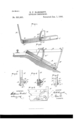
Figure 1 is a perspective View of the improvement in a closed position. Fig. 2 is a side elevation of the improvement as applied on the slope of a railroad bed. Fig. 3 is an end view of the improvement in a closed position; Fig. 4 is a transverse section of the same on the line 44 of Fig. 1. Fig. 5 is an end view of the improvement in a closed position, as seen from the hinged end; and Fig. 6 is an enlarged side elevation of part of the improvement.
The improved instrument is provided with the two bars A and B arranged one alongside the other with the bar B resting, when closed, on a projecting flange or base A, formed integral with the other bar A. The bar 13 is connected at one end by a hinge O to this flange or base A, so as to permit of opening the bars by swinging the bar B upward. v
On the bar B and near the middle thereof is arranged a transversely-extendingboltD engaging a segmental slot E formed in the curved arm of the bail or handle E attached to the bar A. The lower surface of the base is smooth so that it can be set on alevel surface or used to determine a plane surface, the curve of said segmental slot being struck from the center of the hinge G. On the bolt D screws a wing nut I) for securely clamping the said plate on the slotted handle E to fasten the bar B in an angular position relative to the bar A.
On the free end of the bar B is secured a transversely-extending pointer G adapted to indicate on the graduation of an arm F pivoted to the free end of the bar A, the said graduation indicating inches numbered consecutively say from O to 20. On the top of the bar B is arranged a spirit level H of any approved construction, and the graduation on the arm F is so arranged that when the said instrument is applied as shown in Fig. 2, and the bubble of the level H stands at 0, then the pointer G indicates the proper slope on the arm F, for instance in inches per foot, or per any number of feet.
An indicator I, shown in Fig. 6, is arranged on the bar A at the pivot end of the arm F and this indicator is provided with a segmental plate fixed to the arm'A and having a degree scale on which indicates the pointer F of the arm to indicate the angle at which the arm F stands to the bar A.
A clamping plate J held loosely on the pivot F of the arm F extends across the enlarged pivot end of the said arm, the said plate being engaged by a set screw J screwing in the barA and serving to clamp the plate J tightly onto the pivot end of the arm F to lock the latter in place on the side of the bar A. A plumb level K is also arranged in the bar A as shown in Fig. 2.
The instrument is used as follows: For indicating the slope of a road, railroad bed or other place, the bar A is set in an inclined position down the slope, as indicated in Fig. 2, with the upper end of the bar resting on a railroad tie, stone or other suitable support. The bar B is swung upward until the bubble in the level H indicates a level position, with the pointer G reading the proper amount of slope to be given for a certain number of feet, on the arm F. Now, the smooth lower face of the bar A indicates the correct slope and the latter can be filled in if such is necessary or surplus earth removed if required while the instrument remains in position until the proper slope is obtained, and the bar.F can be set to give the outer slope or back slope to the ditch by making the angle between the bar A and the arm F equal to the angle between the two slopes of the ditch. The plate J is arranged in such a manneras to securely hold the arm F in place after the proper adjustment is made. The device may also be used for other purposes. This arm F has somewhat the same relation to the bar A as the bars Aand B have to each other. After setting the bar B to the scale on the bar F, fasten the bar B at that point with the wing nut; and then move the bar F out to any degree desired on the indicator I. In this way both the inner and the outer slopes of a ditch may be obtained and the level glass in the board B .shows that both slopes are correct or when they are correct.
The several parts indicate as follows: First say spread the boards A and B twenty inches. The pointer G on the board 13 points to 20 inches on the bar F. Then fasten the board B at that point with the wing-nut D. Then move the bar F away from the pointer G. Then if the angle between the inner and the outer slopes of the ditch is to be one hundred and twenty degrees move the pointer F of the bar F to 120 on the indicator I. Make the said bar F fast at that point with the part J as already described. The instrument when put in this position and applied in a railroad cut, when the bubble in the bar B stands at 0 two correct slopes are obtained one with the bar A and one with the bar F. Railroad ditches in cuts have two slopes, one sloping from the track and the other bank sloping to the track. Further set the instrument in any position with the different scales and indicator I adjusted as described, and the bubble in the bar B will show when the slopes are correct.
When using to elevate curves on railroad tracks, the bars A and B are spread; say, let the pointer G point to 4: inches on the bar F. Then tighten or stop the bar 13 at that place with the wing-nut D. Then close the bar F so as to have it out of the way. Place the instrument on the track one end on each rail, and when the bubble II in the bar B stands at O'the spread end will be at inches the lowest and give curve any elevation desired.
To use the instrument as a square, the two bars A and B are closed side by side and then the wing-nut D is tightened so the bars will stay. Then in order to apply the device to a piece of timber to cut off square or any angle the top edge of the bar A is placed alongside of the timber with the instrument turned down sidewise, as the level on this kind of work is not used. Then with the bars A and F and indicator, any angle can be laid off as far as the pointer F of the bar will reach, as already described, on indicator I. To use as plumb in upright work, spread the bars A and 13 until the pointer G on the bar 13 points to the desired inclination on the bar F. Then set the barA upright and when the bubble K in the bar A stands at 0 the bar 13 stands or shows the proper inclination.
' Having thus fully described my invention, I claim as new and desire to secure by Letters Paten-t 1; A leveling instrument, comprising a base bar, a level bar hinged to one end thereof, a graduated arm pivoted to the other end of the base bar, an indexon the level bar, a bail or handle secured to the base bar and having a curved arm provided with a guideway that is concentric with the hinge, and a fastening device secured to the level bar and constructed to engage the guideway of the handle, substantially as described.
2. A leveling instrument, comprising a base bar, a level bar hinged to one end thereof, means for securing the level bar relatively to the base bar, a graduated arm pivoted to the free end of the base bar, an indicator arranged on the base bar concentric with the pivot of the graduated arm, a pointer secured to the graduated arm and adapted to indicate on the said indicator, an index on the level bar, and means for fastening the graduated arm relatively to the base bar, substantially as described.
ERASMUS F. HARGRE'IT.
Publications (1)
| Publication Number | Publication Date |
|---|---|
| US531931A true US531931A (en) | 1895-01-01 |
Family
ID=2600704
Family Applications (1)
| Application Number | Title | Priority Date | Filing Date |
|---|---|---|---|
| US531931D Expired - Lifetime US531931A (en) | Leveling-instrument |
Country Status (1)
| Country | Link |
|---|---|
| US (1) | US531931A (en) |
-
0
- US US531931D patent/US531931A/en not_active Expired - Lifetime
Similar Documents
| Publication | Publication Date | Title |
|---|---|---|
| US527815A (en) | Spirit-level attachment | |
| US7392593B2 (en) | Angle meter and spirit level | |
| US531931A (en) | Leveling-instrument | |
| US1410491A (en) | Track gauge and level | |
| US457992A (en) | Spirit-level | |
| US945684A (en) | Square or gaging device. | |
| US1199059A (en) | Instrument for use in raising and lining railroad-tracks. | |
| US1093867A (en) | Adjustable crown-templet. | |
| US743900A (en) | Carpenter's framing square. | |
| US606851A (en) | Railway-tie-plate surfacer and gage | |
| US1127809A (en) | Measuring and leveling instrument. | |
| US645058A (en) | Level. | |
| US820311A (en) | Square and level. | |
| US418712A (en) | Track-gage | |
| US377396A (en) | Plumb-level | |
| US535631A (en) | Apparatus for leveling railroad-tracks | |
| US343634A (en) | Clinometer | |
| US1098253A (en) | Combination adjustable track gage and level. | |
| US1006948A (en) | Miter-gage. | |
| US1922997A (en) | Combination level and gauge | |
| US487375A (en) | Track gage and level | |
| US1006818A (en) | Leveling and plumbing instrument. | |
| US1088394A (en) | Level. | |
| US313659A (en) | Surveyor s instrument | |
| US226723A (en) | Clinometer |