US531559A - Car heater and ventilator - Google Patents
Car heater and ventilator Download PDFInfo
- Publication number
- US531559A US531559A US531559DA US531559A US 531559 A US531559 A US 531559A US 531559D A US531559D A US 531559DA US 531559 A US531559 A US 531559A
- Authority
- US
- United States
- Prior art keywords
- pipe
- pipes
- air
- cars
- valves
- Prior art date
- Legal status (The legal status is an assumption and is not a legal conclusion. Google has not performed a legal analysis and makes no representation as to the accuracy of the status listed.)
- Expired - Lifetime
Links
Images


Classifications
-
- B—PERFORMING OPERATIONS; TRANSPORTING
- B60—VEHICLES IN GENERAL
- B60H—ARRANGEMENTS OF HEATING, COOLING, VENTILATING OR OTHER AIR-TREATING DEVICES SPECIALLY ADAPTED FOR PASSENGER OR GOODS SPACES OF VEHICLES
- B60H1/00—Heating, cooling or ventilating devices
- B60H1/02—Heating, cooling or ventilating devices the heat being derived from the propulsion plant
- B60H1/14—Heating, cooling or ventilating devices the heat being derived from the propulsion plant other than from cooling liquid of the plant
- B60H1/16—Heating, cooling or ventilating devices the heat being derived from the propulsion plant other than from cooling liquid of the plant the air being heated by direct contact with the plant, e.g. air-cooled motor
Definitions
- This invention relates to a system of heating as well as cooling and ventilating railway cars; and the invention consists in a novel organization of heating and ventilating appliances connected to the locomotive and cars and made adjustable so as to permit said appliances to be used either interchangeably or conjointly, all as hereinafter more fully described andset forth in the claims.
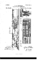
- Figure 1 is a side elevation of a section of "a train of cars equipped with my invention,;aportion of the side of the car being broken away to better illustrate the invention.
- Fig'. 2 is an enlarged plan view of the smoke stack of the locomotive with the funnel'ends of the pipes for receiving the air to be used for heating, ventilating or cooling the cars.
- Fig. 3 is an enlarged vertical longitudinal section of that portion of the train which carries the air heaters and'the'means for conducting the air to and from said heaters.
- Figs. le-and 5 are horizontal sections respectively "on lines Y-Y and X'X-' in Fig. 3.
- Fig. 6 is an enlarged front end .view of one of the funnels of the main air receiving pipes.
- Fig. 7 is partly a side view and partly a longitudinal section of said funnel.
- Fig. 8 is a longitudinal section of one of thecouplings of one of the aforesaid air-receiving pipes.
- Figs. 9, 10, 11, and 12 are transverse sections of various forms of. the air distributing pipes and their connections with the valves bywhich they communicate with the interior of the car.
- Fig. 13 is partly a side elevation and partly a vertical longitudinal section'of a modification of th'e'arrangement'of the car heating and ventilating appliances to a train of cars.
- Fig. 14: is an enlarged horizontal section in line ZZ, Fig. '13.
- Fig. 15 is an enlarged vertical transverse section of the valve through which the car receives the air for either ventilating or heating said car, and
- Fig. 16 is a transverse section of the main e-erepresent the main air-receiving pipes which extend lengthwise over the locomotive B and tender B and are secured to the cab and to opposite sides of the smoke-stack -a which latter attachment I prefer to form of a collar dembracing the stack and fastened thereto and having extending from'it two arms terminating with sleeves cZ'-d'- through which the pipes -ee pass as shown in Fig. 2 of the drawings.
- each of said pipes is funnel-shaped 'and in order to allow said funnel to be closed when desired,'I attach to the funnel a cap A' which is provided .with radial slots A" as more clearly the center of said cap is pivoted the damperrod 19 which extends lengthwise of the interior of the pipe -e-- and has a handle a'- attached to it preferably at or near the cab of the locomotive so as to be easy of access for the engineer or fireman, said handle protruding through a slot in the side of the pipe and having secured to it a collar awhich .loosel'y einbraces the pipe so as to turn with the-handle and maintain the slot closed.
- the attachment of the handle to said collar also vided with radial slots corresponding to those of the cap.
- the damper can be turned to either open .or close the'slots of the cap.
- -O represents an air-heating chamber which may be formed either in a rearward extension of the tender B as shown in Fig. 13 of the drawings or in the front end portion of a car as illustrated in Figs. 1 and 3 of the drawings.
- This chamber is divided into two upper and two lower compartments by a horizontal partition -C' and avertical partition C".
- Said partitions are provided with ports 2-2 through which they can communicate with each other. By means of dampers 1-- and3- said ports can be closed when desired for the purpose hereinafter explained.
- each of the lower compartments is located a sufficient number of steam or hot water radiators -i-z' which may be of any suitable and wellknown construction, to heat the air which is introduced into the compartments by the separate air receiving pipes eeeach of which is provided with two discharge spouts -e communicating respectively with one of the upper and one of the lower compartments of the chamber C and provided with valves 'r rto direct the air current to either of said compartments.
- each of the upper compartments of the chamber -C are located rotary fans '-H 11- having their air receiving mouths h h open to the respective compartments.
- the dischargepipes --15-15 extend from the fans lengthwise of the train either through the interior of the cars as shown in Figs. 1 and 3 of the drawings, or on top of the cars as represented in Fig. 13 of the drawings.
- Said pipes are provided with suitable flexible couplings -g-g-- between the cars to yield to the vibrations or rocking motion of the cars.
- the pipes -15-15 have connected to them suitable valves -77- through which said pipes communicate with the interiors of the cars.
- valve 7- My preferred form of the valve 7- is more clearly illustrated in Fig. 15 of the drawin gs, and it consists of the nozzle -8-- which isprovided with ports 9- in its side and is surrounded by the skeleton cage -6, which supports the valve -10-- which loosely embraces the nozzle and has its stem passing through and pivoted in the lower end of the cage and provided with a suitable handle by which to turn it and thereby open or close the valve.
- the fans -H--H may be driven by an engine -P- receiving steam either direct from the boiler of the locomotive or through the medium of a steam drum -N-- connected by suitable pipes to the aforesaid boiler and to the steam chest of the engine P- as represented in Fig. 14 of the drawings, or by a gear-wheel -P' attached to the fan-shaft as shown in Fig. 40f the drawings and deriving motion from a gear mounted on one of the axles of the tender or car not necessary to be illustrated.
- the fans -H-- rotating in the direction indicated by an arrow in Fig. 3 of the drawings, causes the heated air to be drawn from the chamber --C- and forced through the pipe --15- and IIO valves -'7 into the cars.
- moderate damper 1 and upper dampers -3- in one of the lower compartments can be closed and the steam excluded from the radiators in the latter compartment.
- the front valves or dampers aare to be closed to exclude smoke and gas from the pipes e.
- valves uof the fan in one compartment are to be closed and the valves u'u' in said compartment opened and the adjacent valves 4"- r' of the pipe eleading to said compartment are to be closed while the valves in the other compartment and their companion valves remain adjusted as before described.
- one fan draws the foul air from the cars and forces it into the heating chamber to be reheated and rarefied while i the other fan forces said rarefied air through the pipe 15 into the cars.
- the chamber O is provided with a direct air inlet 0- provided with a damper J'- as shown in Fig. 3 of the drawings.
- the pipe-l5 may be made of different shapes in cross-sectionand provided with a jacket R as shown in Figs. 9, 1O, 11, and 12 of the drawings.
- the upper compartments of the chamber C-, I preferably provide with a direct air inlet -0- from the exterior of the chamber as shown in Fig. 13 of the drawings, said inlet being provided with a suitable damper J for opening and closing the same as may be desired.
- a direct air inlet -0- from the exterior of the chamber as shown in Fig. 13 of the drawings, said inlet being provided with a suitable damper J for opening and closing the same as may be desired.
- Acar-heating and ventilating apparatus consisting of two sets of heaters disposed in separate compartments in a car, two sets of rotary fans likewise in separate compartments in said car, communicating ports in .the partitionsjof said compartments, dampers for opening and closing said ports, separate cold air inlets to the respective compartments, valves controlling said inlets, separate pipes extending from the fans and communicating with the cars of the train, suction-pipes attached to the fans and communicating with the aforesaid cars, and valves connected to the aforesaid pipes for controlling the currents of air to and from the cars as set forth.
- Acarheating and ventilating apparatus consisting of a chamber divided into compartments by vertical and horizontal partitions provided with ports through which to communicate with each other, dampers for opening and closing said ports, heaters in the lower compartments, rotary fans in the upper compartments to receive the air therefrom, main air-conducting pipes extending from the fans and communicating with the interiors of the cars, branch pipes connecting the said main pipes to the fans at points diametrically opposite the attachment of the main pipes, pipes attached to the fans in lines with the branch pipes and leading to the lower compartments, and valves connected to the aforesaid main pipes and branch pipes substantially as and for the purpose set forth.
Landscapes
- Engineering & Computer Science (AREA)
- Chemical & Material Sciences (AREA)
- Combustion & Propulsion (AREA)
- Physics & Mathematics (AREA)
- Thermal Sciences (AREA)
- Mechanical Engineering (AREA)
- Cooling, Air Intake And Gas Exhaust, And Fuel Tank Arrangements In Propulsion Units (AREA)
Description
(No Model.)
; Paented Dec. 25, 1894.
WITNESSES:' NVENTOR;
- flfl ATTORNEY (No Model.) 4.Sheets-Sheet 2.
L. A. PEOKHAM- GAR HEATER AND VENTILATOR.
No. 531,559. Patented D55. 25, 1894.
(No M del.) 4 Sheets-Sheet 3.
- L. A-, PBUKHAM.
GAR HEATERAND VBNTILATOR.
Patented Dec. 25, 1894.
INVENTOR:
WITNESSES.-
ATTORNEY.
was was m1. momuma, wmpmovn u c L. A. PEOKHAMQ CAR HEATER VENTILATOR 4 k heet 4,
(No M m- Patented Dec. 25, 1894.
@IMQ
INVE R. I
$.02; ORNE Ill! . I UNITEDST TESPALTENT OFFIC LUTHERA. E KH M, or. oswEeo FALLS, NEW YORK.
oA HEATER AND VEN TILATO.R.,
SPECIFICATION forming part of Letters Patent No. 531,559, dated. December 25, 1894.
1 Application filed February 14, 1894. Serial No. 500,125: (No model.) i
To all whom it may concern;
- 'Be it known that 1, LUTHER A. PECKHAM,
of Oswego Falls, in the. county of Oswego, in the State of New York, have invented new and useful Improvements in Car Heaters and Ventilators, of which thefollowing,taken in connection with the accompanying drawings, is a full, clear, and exact description.
This invention relates to a system of heating as well as cooling and ventilating railway cars; and the invention consists in a novel organization of heating and ventilating appliances connected to the locomotive and cars and made adjustable so as to permit said appliances to be used either interchangeably or conjointly, all as hereinafter more fully described andset forth in the claims.
In the annexed drawings'Figure 1 is a side elevation of a section of "a train of cars equipped with my invention,;aportion of the side of the car being broken away to better illustrate the invention. Fig'. 2 is an enlarged plan view of the smoke stack of the locomotive with the funnel'ends of the pipes for receiving the air to be used for heating, ventilating or cooling the cars. Fig. 3 is an enlarged vertical longitudinal section of that portion of the train which carries the air heaters and'the'means for conducting the air to and from said heaters. Figs. le-and 5 are horizontal sections respectively "on lines Y-Y and X'X-' in Fig. 3. Fig. 6 is an enlarged front end .view of one of the funnels of the main air receiving pipes. Fig. 7 is partly a side view and partly a longitudinal section of said funnel. Fig. 8 is a longitudinal section of one of thecouplings of one of the aforesaid air-receiving pipes. Figs. 9, 10, 11, and 12 are transverse sections of various forms of. the air distributing pipes and their connections with the valves bywhich they communicate with the interior of the car. Fig. 13 is partly a side elevation and partly a vertical longitudinal section'of a modification of th'e'arrangement'of the car heating and ventilating appliances to a train of cars. Fig. 14: is an enlarged horizontal section in line ZZ, Fig. '13. Fig. 15 is an enlarged vertical transverse section of the valve through which the car receives the air for either ventilating or heating said car, and
Fig. 16 is a transverse section of the main e-erepresent the main air-receiving pipes which extend lengthwise over the locomotive B and tender B and are secured to the cab and to opposite sides of the smoke-stack -a which latter attachment I prefer to form of a collar dembracing the stack and fastened thereto and having extending from'it two arms terminating with sleeves cZ'-d'- through which the pipes -ee pass as shown in Fig. 2 of the drawings. The front end of each of said pipes is funnel-shaped 'and in order to allow said funnel to be closed when desired,'I attach to the funnel a cap A' which is provided .with radial slots A" as more clearly the center of said cap is pivoted the damperrod 19 which extends lengthwise of the interior of the pipe -e-- and has a handle a'- attached to it preferably at or near the cab of the locomotive so as to be easy of access for the engineer or fireman, said handle protruding through a slot in the side of the pipe and having secured to it a collar awhich .loosel'y einbraces the pipe so as to turn with the-handle and maintain the slot closed. The attachment of the handle to said collar also vided with radial slots corresponding to those of the cap. Thus byaturning said rod the damper can be turned to either open .or close the'slots of the cap.
Immediately back of the funnel-shaped end of the pipe 'e said pipe is provided with secondary adjustable air-inlets consisting of ports -16- in the sides ofthe pipe and surrounded by revoluble sleeve or damper 5- which is provided with a suitable lever or handle'5'5- for turning it and has corresponding ports which can be made to register with the ports -16- and thus open said ports when desired forthe purpose hereinafter explained. This portion of the'pipe I e is surrounded by a tube A- fastened to and extending rearwardfrom the 7 shown in Figs. 6'and 7 of the drawings. In 1 funnel-shaped portion of the pipe and larger in diameter than the pipe to form air passages -e'- from the rear end of the tube to the ports 16 as shown in Fig. 7 of the drawings. The purpose of said secondaryadjustable air-inlets is to permit the front damper -a"'-- to be closed to exclude as much as possible snow, sleet and rain from the interior of the pipe -e, and permit the air to enter through said ports 16--, which are shielded by the tube A. 7 To the exterior of the rear end of the tub A is attached an outwardly and forwardly extending flange e"-- which I designate the sleet guard, its purpose being to more elfectually prevent sleet from entering the passages eand ports -16- when opened.
-O represents an air-heating chamber which may be formed either in a rearward extension of the tender B as shown in Fig. 13 of the drawings or in the front end portion of a car as illustrated in Figs. 1 and 3 of the drawings. This chamber is divided into two upper and two lower compartments bya horizontal partition -C' and avertical partition C". Said partitions are provided with ports 2-2 through which they can communicate with each other. By means of dampers 1-- and3- said ports can be closed when desired for the purpose hereinafter explained.
In each of the lower compartments is located a sufficient number of steam or hot water radiators -i-z' which may be of any suitable and wellknown construction, to heat the air which is introduced into the compartments by the separate air receiving pipes eeeach of which is provided with two discharge spouts -e communicating respectively with one of the upper and one of the lower compartments of the chamber C and provided with valves 'r rto direct the air current to either of said compartments.
The radiators -z'--iare heated either by steam or hot water conducted thereto by a pipe -nleading from the boiler of the 10- comotive rearward and connected to the radiators by branch pipes provided with valves mm which can be closed when desired to cool the radiators. --nrepresents pipes leading from the radiators to the water-tank of the tender to facilitate the circulation of the hot water or steam through the radiators and heat the radiators more efiectually and after performing this main function serve to incidentally heat the water in the tank.
In each of the upper compartments of the chamber -C are located rotary fans '-H 11- having their air receiving mouths h h open to the respective compartments.
The dischargepipes --15-15 extend from the fans lengthwise of the train either through the interior of the cars as shown in Figs. 1 and 3 of the drawings, or on top of the cars as represented in Fig. 13 of the drawings. Said pipes are provided with suitable flexible couplings -g-g-- between the cars to yield to the vibrations or rocking motion of the cars. The pipes -15-15 have connected to them suitable valves -77- through which said pipes communicate with the interiors of the cars.
My preferred form of the valve 7- is more clearly illustrated in Fig. 15 of the drawin gs, and it consists of the nozzle -8-- which isprovided with ports 9- in its side and is surrounded by the skeleton cage -6, which supports the valve -10-- which loosely embraces the nozzle and has its stem passing through and pivoted in the lower end of the cage and provided with a suitable handle by which to turn it and thereby open or close the valve.
The fans -H--H may be driven by an engine -P- receiving steam either direct from the boiler of the locomotive or through the medium of a steam drum -N-- connected by suitable pipes to the aforesaid boiler and to the steam chest of the engine P- as represented in Fig. 14 of the drawings, or by a gear-wheel -P' attached to the fan-shaft as shown in Fig. 40f the drawings and deriving motion from a gear mounted on one of the axles of the tender or car not necessary to be illustrated.
In order to adapt the apparatus to ventilating the cars, I attach to each fan I-I- at a point diametrically opposite the attachment of the pipe 15-, a pipe --t-- which taps the pipe 15- between the fan and nearest valve -7. Another pipe t-- in line with the pipe t-- extends from the fan to the section of one of the pipes -ewhich communicates with the lower compartment of the chamber --C as shown in Figs. 1 and 3 of the drawings, the intersection of said pipes being below the valve --1" for the purpose hereinafter described, and for this same purpose the pipes --t and tare provided with the valves --'u, u-- and the portions of the pipe -15 adjacent to the fan are provided with valves -uu-.
The operation of the described apparatus is as follows: When the cars are to be heated, either the damper -a"'- or damper--5 on the front end of the pipe -e is to be opened, according to the condition of the weather, the valve -ron the rear end of said pipe is to be closed, the valve 'r' on the downward branch of said pipe is to be opened, and also the dampers 1- and --33, valves uu-and valves -77--in the cars to be beated, and the valves -u'-u to be closed. The valves --mm being opened to admit steam into the radiators -ii-- causes the chamber -G to be heated. The air entering the pipes -efrom the front end thereof is conducted to the said heated chamber. The fans -H-- rotating in the direction indicated by an arrow in Fig. 3 of the drawings, causes the heated air to be drawn from the chamber --C- and forced through the pipe --15- and IIO valves -'7 into the cars. In moderate damper 1 and upper dampers -3- in one of the lower compartments can be closed and the steam excluded from the radiators in the latter compartment. In case the train has to pass through a tunnel, the front valves or dampers aare to be closed to exclude smoke and gas from the pipes e.
When it is desired tosimultaneously ventilate and heat the cars, the valves uof the fan in one compartment are to be closed and the valves u'u' in said compartment opened and the adjacent valves 4"- r' of the pipe eleading to said compartment are to be closed while the valves in the other compartment and their companion valves remain adjusted as before described. Then one fan draws the foul air from the cars and forces it into the heating chamber to be reheated and rarefied while i the other fan forces said rarefied air through the pipe 15 into the cars.
In hot weather the steam is cut off from the radiators and thus the cold air entering the chamber C, through the pipes ee is forced into the cars by the fans -HH. 4 In order toallow the heating and ventilat ing apparatus to be operated without taking the air through the pipes ee, the chamber O is provided with a direct air inlet 0- provided with a damper J'- as shown in Fig. 3 of the drawings.
The pipe-l5 may be made of different shapes in cross-sectionand provided with a jacket R as shown in Figs. 9, 1O, 11, and 12 of the drawings.
The upper compartments of the chamber C-, I preferably provide with a direct air inlet -0- from the exterior of the chamber as shown in Fig. 13 of the drawings, said inlet being provided with a suitable damper J for opening and closing the same as may be desired. When the cars are to be heated, said inlet is to be closed, and when the cars are to be cooled and ventilated, said inlet is to be opened.
What I claim isp 1. Acar-heating and ventilating apparatus consisting of two sets of heaters disposed in separate compartments in a car, two sets of rotary fans likewise in separate compartments in said car, communicating ports in .the partitionsjof said compartments, dampers for opening and closing said ports, separate cold air inlets to the respective compartments, valves controlling said inlets, separate pipes extending from the fans and communicating with the cars of the train, suction-pipes attached to the fans and communicating with the aforesaid cars, and valves connected to the aforesaid pipes for controlling the currents of air to and from the cars as set forth.
2. Acarheating and ventilating apparatus consisting of a chamber divided into compartments by vertical and horizontal partitions provided with ports through which to communicate with each other, dampers for opening and closing said ports, heaters in the lower compartments, rotary fans in the upper compartments to receive the air therefrom, main air-conducting pipes extending from the fans and communicating with the interiors of the cars, branch pipes connecting the said main pipes to the fans at points diametrically opposite the attachment of the main pipes, pipes attached to the fans in lines with the branch pipes and leading to the lower compartments, and valves connected to the aforesaid main pipes and branch pipes substantially as and for the purpose set forth.
3. In combination with the air-conducting pipe extending lengthwise of the car, the
nozzle -8- provided'with ports in its sides,
the skeleton cage 6 surrounding said nozzle, and the valve 10 pivoted to said cage substantially as described and shown.
4. The combination of the air-receiving pipe e formed with a funnel shaped front end and provided with the cap A' having slots A"A-, the rod 19 extending lengthwise of the interior of said pipe and pivoted to said cap, the damper aattached to said rod, the collar a loosely embracing the pipe, and the lever a' attached to the rear end of the rod l9 and to the aforesaid collar, said lever passing through a transverse slot in the pipe and affording means for turning the rod as set forth.
5. The combination of the air-receiving pipe e formed with a funnel-shaped front end and provided with a slotted cap A' and the ports 16 back of the funnel, the damper a"' pivoted to the cap, and the cylindrical damper -5- embracing the pipe back of its funnel end whereby the front of said pipe may be closed to exclude snow, sleet and rain, and the side ports of the pipe opened to admit air substantially as set forth.
6. The combination of the pipe e formed with a funnel-shaped front endand provided with the slotted cap -A'- and with ports 16 back of the funnel, the damper a" pivoted to said cap, the cylindrical damper -5 embracing the pipe back of its funnel, the tube A extending from the funnel rearward, and the flange e" attached to the rear end of said tube and extending outward and forward therefrom substantially as and for the purpose set forth.
In testimony whereof I have hereunto signed my name this 27th day of January, 1894:-
Witnesses: WM. KOEHLER,
O. L. BENDIXON.
no I
Publications (1)
| Publication Number | Publication Date |
|---|---|
| US531559A true US531559A (en) | 1894-12-25 |
Family
ID=2600333
Family Applications (1)
| Application Number | Title | Priority Date | Filing Date |
|---|---|---|---|
| US531559D Expired - Lifetime US531559A (en) | Car heater and ventilator |
Country Status (1)
| Country | Link |
|---|---|
| US (1) | US531559A (en) |
-
0
- US US531559D patent/US531559A/en not_active Expired - Lifetime
Similar Documents
| Publication | Publication Date | Title |
|---|---|---|
| US1991449A (en) | Furnace | |
| US531559A (en) | Car heater and ventilator | |
| US2268478A (en) | Heating, defrosting, and air conditioning attachment | |
| US373495A (en) | stafford | |
| US1774448A (en) | Automobile heater and ventilator | |
| US373898A (en) | Ventilating apparatus for railway-cars | |
| US177858A (en) | Improvement in car heaters and ventilators | |
| US1262282A (en) | Automobile-heater. | |
| US235265A (en) | Means for heating and ventilating cars | |
| USRE11054E (en) | System of ventilating and heating cars | |
| US464322A (en) | Heater for railroad-cars | |
| US81211A (en) | roberts | |
| US914924A (en) | Car-ventilator. | |
| US430875A (en) | Car-heater | |
| US493388A (en) | Car-heater | |
| US499594A (en) | Car-heater | |
| US168426A (en) | Improvement in apparatus for warming and ventilating railroad-cars | |
| US390701A (en) | Heating and cooling railroad-cars | |
| USRE3509E (en) | Improvement in railroad-car heaters | |
| US449277A (en) | Heating apparatus | |
| US607706A (en) | richardson | |
| US367347A (en) | roberts | |
| US489910A (en) | The nor | |
| US436845A (en) | Heating feed-water | |
| US427863A (en) | hazelton |