US531504A - Frank j - Google Patents
Frank j Download PDFInfo
- Publication number
- US531504A US531504A US531504DA US531504A US 531504 A US531504 A US 531504A US 531504D A US531504D A US 531504DA US 531504 A US531504 A US 531504A
- Authority
- US
- United States
- Prior art keywords
- rack
- pinion
- elongated
- mesh
- frank
- Prior art date
- Legal status (The legal status is an assumption and is not a legal conclusion. Google has not performed a legal analysis and makes no representation as to the accuracy of the status listed.)
- Expired - Lifetime
Links
Images
Classifications
-
- F—MECHANICAL ENGINEERING; LIGHTING; HEATING; WEAPONS; BLASTING
- F03—MACHINES OR ENGINES FOR LIQUIDS; WIND, SPRING, OR WEIGHT MOTORS; PRODUCING MECHANICAL POWER OR A REACTIVE PROPULSIVE THRUST, NOT OTHERWISE PROVIDED FOR
- F03D—WIND MOTORS
- F03D15/00—Transmission of mechanical power
- F03D15/10—Transmission of mechanical power using gearing not limited to rotary motion, e.g. with oscillating or reciprocating members
-
- F—MECHANICAL ENGINEERING; LIGHTING; HEATING; WEAPONS; BLASTING
- F03—MACHINES OR ENGINES FOR LIQUIDS; WIND, SPRING, OR WEIGHT MOTORS; PRODUCING MECHANICAL POWER OR A REACTIVE PROPULSIVE THRUST, NOT OTHERWISE PROVIDED FOR
- F03D—WIND MOTORS
- F03D80/00—Details, components or accessories not provided for in groups F03D1/00 - F03D17/00
-
- F—MECHANICAL ENGINEERING; LIGHTING; HEATING; WEAPONS; BLASTING
- F16—ENGINEERING ELEMENTS AND UNITS; GENERAL MEASURES FOR PRODUCING AND MAINTAINING EFFECTIVE FUNCTIONING OF MACHINES OR INSTALLATIONS; THERMAL INSULATION IN GENERAL
- F16H—GEARING
- F16H19/00—Gearings comprising essentially only toothed gears or friction members and not capable of conveying indefinitely-continuing rotary motion
- F16H19/02—Gearings comprising essentially only toothed gears or friction members and not capable of conveying indefinitely-continuing rotary motion for interconverting rotary or oscillating motion and reciprocating motion
- F16H19/04—Gearings comprising essentially only toothed gears or friction members and not capable of conveying indefinitely-continuing rotary motion for interconverting rotary or oscillating motion and reciprocating motion comprising a rack
- F16H19/043—Gearings comprising essentially only toothed gears or friction members and not capable of conveying indefinitely-continuing rotary motion for interconverting rotary or oscillating motion and reciprocating motion comprising a rack for converting reciprocating movement in a continuous rotary movement or vice versa, e.g. by opposite racks engaging intermittently for a part of the stroke
-
- Y—GENERAL TAGGING OF NEW TECHNOLOGICAL DEVELOPMENTS; GENERAL TAGGING OF CROSS-SECTIONAL TECHNOLOGIES SPANNING OVER SEVERAL SECTIONS OF THE IPC; TECHNICAL SUBJECTS COVERED BY FORMER USPC CROSS-REFERENCE ART COLLECTIONS [XRACs] AND DIGESTS
- Y02—TECHNOLOGIES OR APPLICATIONS FOR MITIGATION OR ADAPTATION AGAINST CLIMATE CHANGE
- Y02E—REDUCTION OF GREENHOUSE GAS [GHG] EMISSIONS, RELATED TO ENERGY GENERATION, TRANSMISSION OR DISTRIBUTION
- Y02E10/00—Energy generation through renewable energy sources
- Y02E10/70—Wind energy
- Y02E10/72—Wind turbines with rotation axis in wind direction
-
- Y—GENERAL TAGGING OF NEW TECHNOLOGICAL DEVELOPMENTS; GENERAL TAGGING OF CROSS-SECTIONAL TECHNOLOGIES SPANNING OVER SEVERAL SECTIONS OF THE IPC; TECHNICAL SUBJECTS COVERED BY FORMER USPC CROSS-REFERENCE ART COLLECTIONS [XRACs] AND DIGESTS
- Y10—TECHNICAL SUBJECTS COVERED BY FORMER USPC
- Y10T—TECHNICAL SUBJECTS COVERED BY FORMER US CLASSIFICATION
- Y10T74/00—Machine element or mechanism
- Y10T74/18—Mechanical movements
- Y10T74/18056—Rotary to or from reciprocating or oscillating
- Y10T74/18088—Rack and pinion type
- Y10T74/18096—Shifting rack
Definitions
- Our invention relates to improvements in xo windmills, and has for its object to provide an improved transmitting gear therefor.
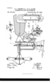
- Figure 1 is a side elevation of a windmill having our improvement applied.
- Fig. 2 is an enlarged transverse section of the transvmitting gear, the section being taken on the line 2-2 of Fig. l.
- Fig. 3 is a sectional plan l View of the same on the lineB-S of Fig. 2.
- Fig. 4 is a detail perspective view of the transmitting gear
- Fig. 5 is a section on line 5-5, Fig. 4.
- the upper end of the tower A is mounted 3o to turn the hollow shaft B supporting the frame B provided at its rear end with the usual vane B2, to hold the wheel in the wind in the usual manner.
- the wheel shafty C carrying at its forward end the wheel D whichmay be of any approved type.
- a pinion H in mesh with an elongated internal rack Hoonnected at its lower end with a rod I extending downwardly through the hollow shaft B to connect with the machinery to 'be driven by the windmill.
- the elongated rack H shown in detail in Figs. 4 5 2, 3, 4, and 5, is provided with a Segmentalauxiliary rack H2, which serves to .regulate the length of the stroke given to the elongatedrack H by the pinion H.y
- the rack H2 is preferably secnredto the rack H by clips AH3 5o formed with or secured to the rack H2, said clips embracing the-rack H and bolted thereto, as shown most clearly in Figs.'4 and 5. It will'thus be seen that by adjusting the auxiliary rack H2 ⁇ on the rack H', the stroke of 'the rack H- can be increased or diminished, 5 5 ⁇ as desired.
- the rack H' during the time it is in mesh at its right hand side ⁇ Y with the pinionH, is moved downward, and when the upper end of the rack H moves in mesh with the pinion H, then' the friction rollersJ andJ leave the upper ends oftheir guide- ⁇ ways to permit the pinion H to draw the rack H to the right to cause the friction roller .I to move in contact'with the outer face of its 9o guideway H4 and the other friction roller J to move in contact with the inner face of its guideway H5.
- the left hand side of the rack H is then in mesh with the pinion H and an upward movement is given to the said rack.
- an elongated internal rack provided with vertically disposed FRANK J. BROWN. ALFRED ALLEN. SOLOMON ALLEN.
Landscapes
- Engineering & Computer Science (AREA)
- General Engineering & Computer Science (AREA)
- Mechanical Engineering (AREA)
- Life Sciences & Earth Sciences (AREA)
- Sustainable Development (AREA)
- Sustainable Energy (AREA)
- Chemical & Material Sciences (AREA)
- Combustion & Propulsion (AREA)
- Transmission Devices (AREA)
Description
" (No'Moael.) v
y 'FQJ- BRU'WN'SI; A. 8v S. ALLEN.
y TRANSMITTING GEAR PORWINDMILLS. No. 531,504.
Patented 13%.]25; 1894-.
,l- INVENTOHS w/TNEssEs.' i 5%@ UNITED STA-TES PATENT OFFICE,
FRANK J. BROWN,l ALFRED" ALLEN, AND SOLOMON ALLEN, OF HALSTEAD,
.y KANSAS.r -i l f TRANsMlT-rlNc-'GEARfF'ORWINDMIYLL'S.
sPEcIFIcAtrroN forming part of Letters Patent No. 531,504, cated Legemeer 25, 1894.
` Y l Application filed December 27, 1893. Serial No. 494,8734. (Nomod'el.)
To all whom it may concern: y
Be it known that we, FRANK J. BROWN ALFREDALLEN, and SOLOMON ALLEN, of Hall stead, in the countyof Harvey and State of Kansas, have invented a new and Improved Transmitting-Gear Vfor Windmills, lof which the following is a full, clear,I and exact 'description.
Our inventionrelates to improvements in xo windmills, and has for its object to provide an improved transmitting gear therefor.
The invention consists Of'certain parts and details and combinations of the same, as will be hereinafter described and thenpointed ou t in the claims. i Reference is to be had to the accompanying drawings, forming a part of this specification, in which similar letters of reference indicate corresponding vparts in all the figures.
Figure 1 is a side elevation of a windmill having our improvement applied. Fig. 2 is an enlarged transverse section of the transvmitting gear, the section being taken on the line 2-2 of Fig. l. Fig. 3 is a sectional plan l View of the same on the lineB-S of Fig. 2.
Fig. 4 is a detail perspective view of the transmitting gear, and Fig. 5 is a section on line 5-5, Fig. 4.
vIn the upper end of the tower A is mounted 3o to turn the hollow shaft B supporting the frame B provided at its rear end with the usual vane B2, to hold the wheel in the wind in the usual manner. On the frame B fare arranged -the bearings B3 and B4, -in which is 3 5 journaled the wheel shafty C carrying at its forward end the wheel D whichmay be of any approved type.
On the shaft C, between the bearings B5 and B4, is secured a pinion H in mesh with an elongated internal rack Hoonnected at its lower end with a rod I extending downwardly through the hollow shaft B to connect with the machinery to 'be driven by the windmill. The elongated rack H shown in detail in Figs. 4 5 2, 3, 4, and 5, is provided witha Segmentalauxiliary rack H2, which serves to .regulate the length of the stroke given to the elongatedrack H by the pinion H.y The rack H2 is preferably secnredto the rack H by clips AH3 5o formed with or secured to the rack H2, said clips embracing the-rack H and bolted thereto, as shown most clearly in Figs.'4 and 5. It will'thus be seen that by adjusting the auxiliary rack H2`on the rack H', the stroke of 'the rack H- can be increased or diminished, 5 5 `as desired.
In order to cause the rack H vto remain in mesh atall times ,with the pinionH, we provide thesaid rack with two vertically disposed guide-ways H4 and H5, on which travel oo the friction rollers J J respectively, held on an arm J2 projecting from the bearing B5 of the main frame B, as plainly shown in Fig.'1. The guideways Ht and H5 are made in sections and the'sections are detachably secured 6 5 to the rack H', so that the guideways can be lengthenedor shortened according to the adjustment of the auxiliary rackV H2 on rack H', by attaching or removing one or more sections of eachy guideway. Now, it will be seen that 7o when the shaft G rotates in the direction of the arrow b, as indicated in Fig. 2, and the pinion H meshes with the lowermost teeth of the elongated rack H', then the friction rollers J and J leave the lower ends of the guideways H4 and H5, respectively, to permit the pinion H to draw the rackH to one side until the pinion H engages the right hand side of the said rack at which time the friction roller J travels on the inside of its guideway H4 and 8o the other friction roller J travels up the outside of its guideway H5. The rack H', during the time it is in mesh at its right hand side\ Y with the pinionH, is moved downward, and when the upper end of the rack H moves in mesh with the pinion H, then' the friction rollersJ andJ leave the upper ends oftheir guide- `ways to permit the pinion H to draw the rack H to the right to cause the friction roller .I to move in contact'with the outer face of its 9o guideway H4 and the other friction roller J to move in contact with the inner face of its guideway H5. The left hand side of the rack H is then in mesh with the pinion H and an upward movement is given to the said rack. By adjusting the segmental rack and lengthening or shortening the guideways H4 and H5 hereinbefore described, the stroke lof therack y H and consequently that of the rodI can be readily increased or diminished.
Having thus fully described our invention, we claim as new and desire to secure by Letters Patent- 1. The combination with a driven shaft, a pinion thereon, an elongated internal rack, and means for holding the rack in mesh with the pinion, of an auxiliary segmental rack adjustably secured to the elongated rack, substantially as and for the purpose set forth.
2. The combination with a driven shaft, a pinion thereon, and an elongated internal rack meshing with the pinion, of an auxiliary segmental rack adj ustably secured to the elongated rack, adjustable guides on the elongated rack, and projections on a fixed support for engaging the guides to hold the rack in mesh with the pinion, substantially as described.
3. In a transmitting gear, an elongated internal rack provided with vertically disposed FRANK J. BROWN. ALFRED ALLEN. SOLOMON ALLEN.
Witnesses:
DAVID A. SMITH, D. S. MARCY.
Publications (1)
| Publication Number | Publication Date |
|---|---|
| US531504A true US531504A (en) | 1894-12-25 |
Family
ID=2600279
Family Applications (1)
| Application Number | Title | Priority Date | Filing Date |
|---|---|---|---|
| US531504D Expired - Lifetime US531504A (en) | Frank j |
Country Status (1)
| Country | Link |
|---|---|
| US (1) | US531504A (en) |
-
0
- US US531504D patent/US531504A/en not_active Expired - Lifetime
Similar Documents
| Publication | Publication Date | Title |
|---|---|---|
| US531504A (en) | Frank j | |
| US679109A (en) | Windmill. | |
| US1053746A (en) | Saw tensioning and straightening machine. | |
| US427846A (en) | garcia-sanchez | |
| US494567A (en) | El wood t | |
| US400065A (en) | dumont | |
| US485696A (en) | Log-turner | |
| US1067697A (en) | Transmission mechanism. | |
| US999188A (en) | Windmill. | |
| US899872A (en) | Windmill-gearing. | |
| US571785A (en) | Fourth to john ii | |
| US427975A (en) | Windmill | |
| US838837A (en) | Windmill. | |
| US858482A (en) | Mechanical movement. | |
| US87646A (en) | darby | |
| US1402966A (en) | Mechanical movement for windmills and the like | |
| US142256A (en) | Improvement in wind-wheels | |
| US77674A (en) | Improvement in apparatus foe produced motive-power | |
| US255432A (en) | Benjamin h | |
| US635175A (en) | Tellurian. | |
| US261442A (en) | gorrell | |
| US658475A (en) | Windmill. | |
| US585851A (en) | Mechanical movement | |
| US1155847A (en) | Gearing. | |
| US247409A (en) | Windmill |