US5313135A - Headlamp capsule - Google Patents
Headlamp capsule Download PDFInfo
- Publication number
- US5313135A US5313135A US07/816,163 US81616392A US5313135A US 5313135 A US5313135 A US 5313135A US 81616392 A US81616392 A US 81616392A US 5313135 A US5313135 A US 5313135A
- Authority
- US
- United States
- Prior art keywords
- base
- capsule
- web
- coupling
- lamp capsule
- Prior art date
- Legal status (The legal status is an assumption and is not a legal conclusion. Google has not performed a legal analysis and makes no representation as to the accuracy of the status listed.)
- Expired - Fee Related
Links
- 239000002775 capsule Substances 0.000 title claims abstract description 65
- 230000008878 coupling Effects 0.000 claims description 31
- 238000010168 coupling process Methods 0.000 claims description 31
- 238000005859 coupling reaction Methods 0.000 claims description 31
- 229910052736 halogen Inorganic materials 0.000 claims description 2
- 229910052721 tungsten Inorganic materials 0.000 claims description 2
- 239000010937 tungsten Substances 0.000 claims description 2
- 230000013011 mating Effects 0.000 claims 1
- -1 tungsten halogen Chemical class 0.000 claims 1
- 239000002184 metal Substances 0.000 description 8
- 229910052751 metal Inorganic materials 0.000 description 8
- 238000007373 indentation Methods 0.000 description 7
- 239000004033 plastic Substances 0.000 description 3
- 239000010453 quartz Substances 0.000 description 3
- VYPSYNLAJGMNEJ-UHFFFAOYSA-N silicon dioxide Inorganic materials O=[Si]=O VYPSYNLAJGMNEJ-UHFFFAOYSA-N 0.000 description 3
- 229910001369 Brass Inorganic materials 0.000 description 2
- 239000010951 brass Substances 0.000 description 2
- 239000011521 glass Substances 0.000 description 2
- 238000000034 method Methods 0.000 description 2
- 230000003287 optical effect Effects 0.000 description 2
- 239000004956 Amodel Substances 0.000 description 1
- ZOKXTWBITQBERF-UHFFFAOYSA-N Molybdenum Chemical compound [Mo] ZOKXTWBITQBERF-UHFFFAOYSA-N 0.000 description 1
- 238000005452 bending Methods 0.000 description 1
- 238000010891 electric arc Methods 0.000 description 1
- 150000002367 halogens Chemical class 0.000 description 1
- 238000010438 heat treatment Methods 0.000 description 1
- 230000014759 maintenance of location Effects 0.000 description 1
- 239000000463 material Substances 0.000 description 1
- 238000012986 modification Methods 0.000 description 1
- 230000004048 modification Effects 0.000 description 1
- 229910052750 molybdenum Inorganic materials 0.000 description 1
- 239000011733 molybdenum Substances 0.000 description 1
- 229920001169 thermoplastic Polymers 0.000 description 1
- 239000004416 thermosoftening plastic Substances 0.000 description 1
- WFKWXMTUELFFGS-UHFFFAOYSA-N tungsten Chemical compound [W] WFKWXMTUELFFGS-UHFFFAOYSA-N 0.000 description 1
Images


Classifications
-
- H—ELECTRICITY
- H01—ELECTRIC ELEMENTS
- H01J—ELECTRIC DISCHARGE TUBES OR DISCHARGE LAMPS
- H01J5/00—Details relating to vessels or to leading-in conductors common to two or more basic types of discharge tubes or lamps
- H01J5/50—Means forming part of the tube or lamps for the purpose of providing electrical connection to it
- H01J5/54—Means forming part of the tube or lamps for the purpose of providing electrical connection to it supported by a separate part, e.g. base
- H01J5/56—Shape of the separate part
-
- F—MECHANICAL ENGINEERING; LIGHTING; HEATING; WEAPONS; BLASTING
- F21—LIGHTING
- F21V—FUNCTIONAL FEATURES OR DETAILS OF LIGHTING DEVICES OR SYSTEMS THEREOF; STRUCTURAL COMBINATIONS OF LIGHTING DEVICES WITH OTHER ARTICLES, NOT OTHERWISE PROVIDED FOR
- F21V19/00—Fastening of light sources or lamp holders
- F21V19/02—Fastening of light sources or lamp holders with provision for adjustment, e.g. for focusing
Definitions
- the invention relates to lamps and particularly to electric lamps. More particularly the invention is concerned with a support structure for an electric lamp.
- Vehicle headlamps have required projected light patterns that are achieved through optical designs of the reflectors and lenses. Underlying the optical design is the requirement that the light source be located in an expected position. If the light source is displaced, even a quarter millimeter, the beam at a hundred meters can be off by a meter or more. Accurately locating the headlamp filament is then necessary for headlamp quality. There is then a need for a means of finely adjusting the headlamp filament position. It is equally important to keep the cost of the headlamp capsule low, and maintain durability. There is the a need for an inexpensive, durable means for finely adjusting the headlamp filament position.
- a headlamp capsule may be formed with a lamp capsule having an envelope, a light source enclosed in the envelope, at least two leads for powering the light source extending through an envelope seal for connection.
- the lamp capsule is coupled by a first base coupling means to a base.
- a second base coupling means couples the base to a first side of a mechanically adjustable web. The second side of the web couples to means for mounting the headlamp capsule.
- Means for supporting electrical connectors are formed in the base, and at least two electrical connectors are held in place by the base, and electrically connected to the lamp capsule leads.
- FIG. 1 shows an elevational view of a preferred embodiment of a headlamp capsule.
- FIG. 2 shows a top view of a headlamp capsule.
- FIG. 3 shows a bottom view of a headlamp capsule.
- FIG. 4 shows an front elevational view of a base.
- FIG. 5 shows a side elevational view of a base.
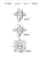
- FIG. 6 a top view of a base.
- FIG. 7 shows an front elevational view of a base and web.
- FIG. 8 side elevational view of a base and web.
- FIG. 9 s a bottom view of a base and web.
- FIG. 1 shows a preferred embodiment of a headlamp capsule 10.
- the headlamp capsule 10 may be assembled from a lamp capsule 15, a base 20 and an adjustable web 35.
- the lamp capsule 15 has an envelope, a light source, a seal and at least two leads.
- the envelope is formed from a light transmissive material, such as glass or quartz, and has a tubular, or bulbous shape enclosing an internal volume. Positioned in the internal volume is a light source.
- the light source may be an arc discharge, or other electrically powered light source.
- the preferred light source is a coiled tungsten filament enclosed with a halogen environment.
- a seal that may have any convenient form. Lamp capsules are commonly sealed by heating an end of the quartz tube to a plastic state, and then pressing the plastic quartz between two press heads.
- the press heads may include a variety of formed features to enhance the seal, or to enhance the coupling or alignment of the lamp capsule 15 in a support device.
- the preferred lamp capsule 15 is a press seal with two side by side bumps on each side of the press seal area.
- lamp capsule 15 is shown as a tubular, double filamented headlamp capsule 10 having three leads.
- FIGS. 2, and 3 show a top, and bottom view of a lamp capsule 15.
- FIG. 4, 5 and 6 show front, side and top views of a base.
- the preferred base 20 is single piece molded from a glass filled thermoplastic such as Amodel 45.
- the base 20 includes a first base coupling means for retaining or coupling to the lamp capsule 15.
- the coupling mechanism between the lamp capsule 15 and the base 20 is not felt to be crucial, and numerous methods for making the first base coupling respect to the are known.
- the base 20 has a generally cylindrical structure, with one end formed with two opposed arms defining a cavity therebetween to receive, and couple with a portion of the press seal of the lamp capsule 15.
- the plastic arms are slightly flexible and may be spread a small amount to clip to the press seal and thereby hold the lamp capsule 15.
- the opposed arms each include side by side dimples formed in the interior wall to mate with the side by side bumps formed on each side of the press seal.
- the base 20 also includes a second base coupling means to couple the base 20 to the web 35.
- a second base coupling means to couple the base 20 to the web 35.
- formed approximately midway along an exterior of the base 20 is a means for coupling the base 20 to the web 35, such as a circumferential side notch 25.
- the side notch 25 may be one or more indentations 30.
- the side notch 25 then roughly locates the base 20 vertically with respect to the web 35, while indentations 30 roughly locate the base 20 rotationally with respect to the web 35.
- the lamp capsule 10 also includes a web 35.
- the inclusion of the adjustable web 35 allows accurate, corrective repositioning of the light source with respect to the lamp capsule 15 mounting.
- the web 35 has a first coupling side, such as an inner support ring 40.
- the web 35 also includes a second coupling side, such as a metal ring, for coupling to a reflector housing or similar support structure.
- Intermediate the first coupling side and the second coupling side are two or more adjustable cross linkages 50.
- the lamp capsule 15 may be correctively repositioned while being held by the web 35 by reshaping the adjustable cross linkages 50.
- the preferred web 35 is a single, stamped metal piece with an inner support ring 40 joined to a series of metal cross linkages 50 that in turn couple to an outer support ring 55.
- the preferred web 35 has an inner support ring 40, two or more malleable cross linkages 50, and an outer support ring 55.
- the inner support ring 40 may be a metal ring with a width and diameter sufficient to fit snuggly in or against the side notch 25.
- the inner support ring 40 may further include a number of bendable tabs or dimples 45 formed along the inside edge of the inner support ring 40 to fit snuggly with corresponding indentations 30 formed in the side notch 25. In one embodiment, four indentations 30 were formed in the side notch 25, that paired with four corresponding dimples 45 formed along the inner support ring 40.
- the base 20 indentations 30 may be aligned with and coupled to the dimples 45 formed on the preferred inner support ring 40.
- the cross linkages 50 are preferrably positioned equal angularly around the inner support ring 40, and extend radially outward.
- the preferred cross linkages 50 comprise three flat, malleable metal cross linkages 50 angularly spaced around the lamp axis at about one hundred and twenty degrees one from the other.
- the three metal cross linkages 50 with sufficient force, are malleable, so the inner support ring 40 may be raised, lowered or angled with respect to the outer support ring 55.
- the metal cross linkages 50 are nonetheless sufficiently stiff that once the lamp capsule 15 is aligned by adjusting the cross linkages 50, the reshaped cross linkages 50 hold the lamp capsule 15 firmly.
- the cross linkages 50 may also include rippled, or accordion like features to provide a greater range of adjustment, and may include only two, three, or more than three cross linkages 50.
- the cross linkages 50 also couple to an outer support ring 55.
- the preferred outer support ring 55 is also a metal ring.
- the outer support ring 55 may include positioning keys, or locking features for mounting the lamp capsule to a support structure.
- the preferred means for coupling to a support structure such as a headlamp reflector housing, is an H4 type headlamp coupling as typically used in European style headlamps.
- web 35 is shown as a inner support ring 40 supported by three flat cross linkages 50 coupled to an outer support ring 55.
- the lamp capsule 15, is then held by the base 20, and the base 20 is held by web 35.
- the lamp capsule 15's position may then be adjusted by adjusting the web 35.
- the preferred lamp capsule 15 is electrically connected through the leads to the lug connectors 60.
- the lug connectors 60 are shown as a flat, brass blade type lug connectors 60, having a right angle shape.
- One leg of each right angle lug connector 60 is staked to the base with a lamp lead soldered or welded to the lug.
- the other leg of each right angle lug projects away from the base 20 providing a plug type connector.
- Other lug connector 60 forms may be used.
- the accurately adjustable headlamp capsule 10 may be assembled by forming a lamp capsule 15, providing a base 20 with an adjustable web 35, positioning the lamp capsule 15 in the base 20, supported by the web 35, and adjusting the web 35 to accurately position the light source. Electrical connections for the lamp leads are then completed.
- the first step is to form a lamp capsule 15 with a designed coupling region.
- a base 20 is molded and lug connectors 60 are staked to the base 20.
- the base 20 is then coupled to an adjustable web 35.
- the base 20 may be positioned in the web 35 by snapping the base 20 into the inner support ring 40, rotating the base 20 to align the base 20's indentations 30 with the inner support ring 40's tabs or dimples 45, and then, if necessary, bending the tabs of the inner support ring 40 into the indentations 30.
- the lamp capsule 15 leads are then threaded through formed passages of the base, and through the eyelets of the lug connectors 60.
- the lamp capsule 15 is then clipped into the receiving cavity formed in the base 20.
- the lamp capsule 15 is then held by the base 20 and the base 20 is held by the web 35.
- the lamp capsule 15, base 20 and web 35 assembly is then examined for proper location of the light source with respect to the web 35's outer support ring 55. If the light source is not properly located, the web 35's cross linkages 50 may be bent, twisted or turned, to allow the lamp capsule 15 to be shifted with respect to outer support ring 70 thereby relocating the light source closer to, if not exactly into proper position.
- the preferred alignment method is to locate the lamp capsule 15, base 20 and web 35 assembly in a computer driven vision sensor, where the light source position is detected and compared with a reference. If the light source is not in proper position, mechanical arms are brought into contact with the cross linkages 50. The arms may then press on the cross linkages 50, causing the light source to approach or come into exact alignment with respect to the reference. The arms are then withdrawn, leaving the reshaped web 35 adjusted to retain the lamp capsule 15 in proper position.
- the lamp leads are then coupled to the adjacent lug connectors 60.
- the form of coupling depends in part on the preferred form of the electrical connectors 60.
- the Applicant prefers flat brass lug connectors with formed eyelets staked to the bottom of the base 20. Round molybdenum leads wires, are threaded through the base 20 and lug connector eyelets, and soldered to the lug connectors. The lead to lug connection is performed after to the light source alignment, so the final corrective positioning does not tension the lead and crack the envelope.
Landscapes
- Engineering & Computer Science (AREA)
- General Engineering & Computer Science (AREA)
- Non-Portable Lighting Devices Or Systems Thereof (AREA)
Abstract
A headlamp capsule having lamp capsule, base, web and connectors, is disclosed. The web comprises an inner support, an outer support, and a plurality of cross linkages that may be adjusted. The lamp capsule is held by the base, and the base is in turn held by the adjustable web. Adjusting the web after the lamp capsule has be positioned in the base, allows for corrective repositioning of the light source. The small number of parts, and the simplicity of each part makes the total structure very inexpensive, and still yields an accurately adjustable headlamp capsule.
Description
1. Technical Field
The invention relates to lamps and particularly to electric lamps. More particularly the invention is concerned with a support structure for an electric lamp.
2. Background Art
Vehicle headlamps have required projected light patterns that are achieved through optical designs of the reflectors and lenses. Underlying the optical design is the requirement that the light source be located in an expected position. If the light source is displaced, even a quarter millimeter, the beam at a hundred meters can be off by a meter or more. Accurately locating the headlamp filament is then necessary for headlamp quality. There is then a need for a means of finely adjusting the headlamp filament position. It is equally important to keep the cost of the headlamp capsule low, and maintain durability. There is the a need for an inexpensive, durable means for finely adjusting the headlamp filament position.
A headlamp capsule may be formed with a lamp capsule having an envelope, a light source enclosed in the envelope, at least two leads for powering the light source extending through an envelope seal for connection. The lamp capsule is coupled by a first base coupling means to a base. A second base coupling means couples the base to a first side of a mechanically adjustable web. The second side of the web couples to means for mounting the headlamp capsule. Means for supporting electrical connectors are formed in the base, and at least two electrical connectors are held in place by the base, and electrically connected to the lamp capsule leads.
FIG. 1 shows an elevational view of a preferred embodiment of a headlamp capsule.
FIG. 2 shows a top view of a headlamp capsule.
FIG. 3 shows a bottom view of a headlamp capsule.
FIG. 4 shows an front elevational view of a base.
FIG. 5 shows a side elevational view of a base.
FIG. 6 a top view of a base.
FIG. 7 shows an front elevational view of a base and web.
FIG. 8 side elevational view of a base and web.
FIG. 9 s a bottom view of a base and web.
FIG. 1 shows a preferred embodiment of a headlamp capsule 10. The headlamp capsule 10 may be assembled from a lamp capsule 15, a base 20 and an adjustable web 35.
The lamp capsule 15 has an envelope, a light source, a seal and at least two leads. The envelope is formed from a light transmissive material, such as glass or quartz, and has a tubular, or bulbous shape enclosing an internal volume. Positioned in the internal volume is a light source. The light source may be an arc discharge, or other electrically powered light source. The preferred light source is a coiled tungsten filament enclosed with a halogen environment. Along one end of the preferred lamp capsule 20 is a seal that may have any convenient form. Lamp capsules are commonly sealed by heating an end of the quartz tube to a plastic state, and then pressing the plastic quartz between two press heads. The press heads may include a variety of formed features to enhance the seal, or to enhance the coupling or alignment of the lamp capsule 15 in a support device. The preferred lamp capsule 15 is a press seal with two side by side bumps on each side of the press seal area. By way of example lamp capsule 15 is shown as a tubular, double filamented headlamp capsule 10 having three leads. FIGS. 2, and 3 show a top, and bottom view of a lamp capsule 15.
FIG. 4, 5 and 6 show front, side and top views of a base. The preferred base 20 is single piece molded from a glass filled thermoplastic such as Amodel 45. The base 20 includes a first base coupling means for retaining or coupling to the lamp capsule 15. The coupling mechanism between the lamp capsule 15 and the base 20 is not felt to be crucial, and numerous methods for making the first base coupling respect to the are known. In the preferred embodiment, the base 20 has a generally cylindrical structure, with one end formed with two opposed arms defining a cavity therebetween to receive, and couple with a portion of the press seal of the lamp capsule 15. The plastic arms are slightly flexible and may be spread a small amount to clip to the press seal and thereby hold the lamp capsule 15. Features formed along the press seal may then conformally couple with corresponding features formed on the base 20's internal wall to thereby enhance coupling and retention of the lamp capsule 15 by the base 20. In the preferred embodiment, the opposed arms each include side by side dimples formed in the interior wall to mate with the side by side bumps formed on each side of the press seal.
The base 20 also includes a second base coupling means to couple the base 20 to the web 35. In the preferred embodiment, formed approximately midway along an exterior of the base 20 is a means for coupling the base 20 to the web 35, such as a circumferential side notch 25. In the side notch 25 may be one or more indentations 30. The side notch 25 then roughly locates the base 20 vertically with respect to the web 35, while indentations 30 roughly locate the base 20 rotationally with respect to the web 35.
The lamp capsule 10 also includes a web 35. The inclusion of the adjustable web 35 allows accurate, corrective repositioning of the light source with respect to the lamp capsule 15 mounting. To mate with the base 20, the web 35 has a first coupling side, such as an inner support ring 40. The web 35 also includes a second coupling side, such as a metal ring, for coupling to a reflector housing or similar support structure. Intermediate the first coupling side and the second coupling side are two or more adjustable cross linkages 50. The lamp capsule 15 may be correctively repositioned while being held by the web 35 by reshaping the adjustable cross linkages 50. The preferred web 35 is a single, stamped metal piece with an inner support ring 40 joined to a series of metal cross linkages 50 that in turn couple to an outer support ring 55.
The preferred web 35 has an inner support ring 40, two or more malleable cross linkages 50, and an outer support ring 55. The inner support ring 40 may be a metal ring with a width and diameter sufficient to fit snuggly in or against the side notch 25. The inner support ring 40 may further include a number of bendable tabs or dimples 45 formed along the inside edge of the inner support ring 40 to fit snuggly with corresponding indentations 30 formed in the side notch 25. In one embodiment, four indentations 30 were formed in the side notch 25, that paired with four corresponding dimples 45 formed along the inner support ring 40. The base 20 indentations 30 may be aligned with and coupled to the dimples 45 formed on the preferred inner support ring 40.
Positioned along web 35 are two or more malleable cross linkages 50. The cross linkages 50 are preferrably positioned equal angularly around the inner support ring 40, and extend radially outward. The preferred cross linkages 50 comprise three flat, malleable metal cross linkages 50 angularly spaced around the lamp axis at about one hundred and twenty degrees one from the other. The three metal cross linkages 50, with sufficient force, are malleable, so the inner support ring 40 may be raised, lowered or angled with respect to the outer support ring 55. The metal cross linkages 50 are nonetheless sufficiently stiff that once the lamp capsule 15 is aligned by adjusting the cross linkages 50, the reshaped cross linkages 50 hold the lamp capsule 15 firmly. The cross linkages 50 may also include rippled, or accordion like features to provide a greater range of adjustment, and may include only two, three, or more than three cross linkages 50. The cross linkages 50 also couple to an outer support ring 55.
The preferred outer support ring 55 is also a metal ring. The outer support ring 55 may include positioning keys, or locking features for mounting the lamp capsule to a support structure. The preferred means for coupling to a support structure, such as a headlamp reflector housing, is an H4 type headlamp coupling as typically used in European style headlamps. By way of example, web 35 is shown as a inner support ring 40 supported by three flat cross linkages 50 coupled to an outer support ring 55. The lamp capsule 15, is then held by the base 20, and the base 20 is held by web 35. The lamp capsule 15's position may then be adjusted by adjusting the web 35.
The preferred lamp capsule 15 is electrically connected through the leads to the lug connectors 60. By way of example, the lug connectors 60 are shown as a flat, brass blade type lug connectors 60, having a right angle shape. One leg of each right angle lug connector 60 is staked to the base with a lamp lead soldered or welded to the lug. The other leg of each right angle lug projects away from the base 20 providing a plug type connector. Other lug connector 60 forms may be used.
The accurately adjustable headlamp capsule 10 may be assembled by forming a lamp capsule 15, providing a base 20 with an adjustable web 35, positioning the lamp capsule 15 in the base 20, supported by the web 35, and adjusting the web 35 to accurately position the light source. Electrical connections for the lamp leads are then completed.
The first step is to form a lamp capsule 15 with a designed coupling region. A base 20 is molded and lug connectors 60 are staked to the base 20. The base 20 is then coupled to an adjustable web 35. The base 20 may be positioned in the web 35 by snapping the base 20 into the inner support ring 40, rotating the base 20 to align the base 20's indentations 30 with the inner support ring 40's tabs or dimples 45, and then, if necessary, bending the tabs of the inner support ring 40 into the indentations 30. The lamp capsule 15 leads are then threaded through formed passages of the base, and through the eyelets of the lug connectors 60. The lamp capsule 15 is then clipped into the receiving cavity formed in the base 20. The lamp capsule 15 is then held by the base 20 and the base 20 is held by the web 35. The lamp capsule 15, base 20 and web 35 assembly is then examined for proper location of the light source with respect to the web 35's outer support ring 55. If the light source is not properly located, the web 35's cross linkages 50 may be bent, twisted or turned, to allow the lamp capsule 15 to be shifted with respect to outer support ring 70 thereby relocating the light source closer to, if not exactly into proper position.
The preferred alignment method is to locate the lamp capsule 15, base 20 and web 35 assembly in a computer driven vision sensor, where the light source position is detected and compared with a reference. If the light source is not in proper position, mechanical arms are brought into contact with the cross linkages 50. The arms may then press on the cross linkages 50, causing the light source to approach or come into exact alignment with respect to the reference. The arms are then withdrawn, leaving the reshaped web 35 adjusted to retain the lamp capsule 15 in proper position.
The lamp leads are then coupled to the adjacent lug connectors 60. The form of coupling depends in part on the preferred form of the electrical connectors 60. The Applicant prefers flat brass lug connectors with formed eyelets staked to the bottom of the base 20. Round molybdenum leads wires, are threaded through the base 20 and lug connector eyelets, and soldered to the lug connectors. The lead to lug connection is performed after to the light source alignment, so the final corrective positioning does not tension the lead and crack the envelope.
While there have been shown and described what are at present considered to be the preferred embodiments of the invention, it will be apparent to those skilled in the art that various changes and modifications can be made herein without departing from the scope of the invention defined by the appended claims.
Claims (10)
1. A headlamp capsule comprising:
a) a lamp capsule having an envelope, a light source enclosed in the envelope, at least two leads for powering the light source extending through an envelope seal for the leads,
b) a base, including a first coupling means for coupling the base to the lamp capsule, and a second coupling means for coupling the base to the web,
c) web having a first support side coupled to the second coupling means of the base, a second support side for coupling the web to a headlamp capsule support, and at least two adjustable cross linkages coupled intermediate the first support side and the second support side, and
d) at least two electrical connectors held in place by the base, and electrically connected to the lamp capsule leads.
2. The apparatus in claim 1, wherein the first means for coupling the base to the lamp capsule is a formed interior wall.
3. The apparatus in claim 1, wherein the second coupling means is a formed exterior wall of the base.
4. The apparatus in claim 1, wherein the lamp capsule is a tungsten halogen lamp.
5. The apparatus in claim 1, wherein the light source is a coiled filament.
6. The apparatus in claim 1, wherein the seal is a press seal that seals the at least two electrical leads.
7. The apparatus in claim 1, wherein the base includes a wall defining a cavity to receive and couple to the lamp capsule.
8. A headlamp capsule comprising:
a) a lamp capsule having an envelope, a light source, a seal and at least two leads,
b) a base supporting the lamp capsule, and an adjustable web, wherein
i) the base includes means for coupling the base to the lamp capsule and means for coupling the base to the web, and
ii) the web includes an inner support coupled to the base, an outer support having a coupling means for mating with a headlamp capsule receptacle, and at least two malleable cross linkages coupling the inner support to the outer support, and
c) at least two electrical connectors held in place by the base, and electrically connected to the lamp capsule leads.
9. The apparatus in claim 8, wherein the inner support is a ring.
10. The apparatus in claim 8, wherein the outer support is a ring.
Priority Applications (1)
| Application Number | Priority Date | Filing Date | Title |
|---|---|---|---|
| US07/816,163 US5313135A (en) | 1992-01-02 | 1992-01-02 | Headlamp capsule |
Applications Claiming Priority (1)
| Application Number | Priority Date | Filing Date | Title |
|---|---|---|---|
| US07/816,163 US5313135A (en) | 1992-01-02 | 1992-01-02 | Headlamp capsule |
Publications (1)
| Publication Number | Publication Date |
|---|---|
| US5313135A true US5313135A (en) | 1994-05-17 |
Family
ID=25219843
Family Applications (1)
| Application Number | Title | Priority Date | Filing Date |
|---|---|---|---|
| US07/816,163 Expired - Fee Related US5313135A (en) | 1992-01-02 | 1992-01-02 | Headlamp capsule |
Country Status (1)
| Country | Link |
|---|---|
| US (1) | US5313135A (en) |
Cited By (13)
| Publication number | Priority date | Publication date | Assignee | Title |
|---|---|---|---|---|
| USD370541S (en) | 1994-02-23 | 1996-06-04 | Brokelmann, Jaeger & Busse Gmbh & Co. | Lamp holder |
| US5659221A (en) * | 1996-03-26 | 1997-08-19 | Osram Sylvania, Inc. | High intensity discharge headlamp assembly |
| US6093999A (en) * | 1997-04-28 | 2000-07-25 | Osram Sylvania Inc. | Vehicle lamp with shaped envelope interior providing a light-trapping dome |
| US6210021B1 (en) * | 1998-09-23 | 2001-04-03 | Patent-Treuhand-Gesellschaft Fuer Elektrische Gluehlampen Mbh | Electric lamp with rotatable base including compressed contacts |
| US20020060912A1 (en) * | 2000-11-21 | 2002-05-23 | Patent-Treuhand-Gesellschaft Fur Elektrische Gluhlampen Mbh | High-pressure discharge lamp for motor vehicle headlights |
| US6738565B2 (en) * | 2001-06-30 | 2004-05-18 | Ic Tech Co., Ltd. | Halogen lamp coupling structure for electric heater |
| US6856090B2 (en) | 2001-10-23 | 2005-02-15 | Federal-Mogul Worldwide, Inc. | Incandescent halogen lamp having flattened filament support leads |
| WO2006016314A1 (en) * | 2004-08-05 | 2006-02-16 | Philips Intellectual Property & Standards Gmbh | Lamp having improved vibration damping |
| WO2008006538A1 (en) * | 2006-07-11 | 2008-01-17 | Dsm Ip Assets B.V. | Lamp sockets |
| US20090116253A1 (en) * | 2005-06-17 | 2009-05-07 | Patent-Treuhand-Gesellschaft Fur Elektrische Gluhl | Lamp Ring, Lamp and Base Mounting Machine |
| US20090134763A1 (en) * | 2007-11-26 | 2009-05-28 | Miller Jack V | 3-Way parabolic reflector lamp |
| US20100213815A1 (en) * | 2009-02-20 | 2010-08-26 | Osram Sylvania Inc. | Halogen lamp capsule support for plastic base |
| US20100213814A1 (en) * | 2009-02-20 | 2010-08-26 | Osram Sylvania Inc. | Retaining sleeve with retention feature |
Citations (5)
| Publication number | Priority date | Publication date | Assignee | Title |
|---|---|---|---|---|
| DE3047210A1 (en) * | 1980-12-15 | 1982-07-15 | Patent-Treuhand-Gesellschaft für elektrische Glühlampen mbH, 8000 München | Motor vehicle illumination lamp assembly - has slotted cylindrical cap with relocatable adjustment ring and projecting flat terminals |
| US4492893A (en) * | 1981-07-22 | 1985-01-08 | Patent-Treuhand Gesellschaft Fur Elektrische Gluhlampen Gmbh | Dual filament halogen cycle automotive-type incandescent lamp |
| US4547838A (en) * | 1983-09-05 | 1985-10-15 | Koito Seisakusho Co., Ltd. | Electric lamp assembly with a molded plastic base |
| US5029057A (en) * | 1989-11-20 | 1991-07-02 | Gte Products Corporation | Clipped together lamp base |
| US5229683A (en) * | 1990-08-27 | 1993-07-20 | Patent-Treuhand-Gesellschaft Fur Elektrische Gluhlampen M.B.H. | Electric lamp with cementless base |
-
1992
- 1992-01-02 US US07/816,163 patent/US5313135A/en not_active Expired - Fee Related
Patent Citations (5)
| Publication number | Priority date | Publication date | Assignee | Title |
|---|---|---|---|---|
| DE3047210A1 (en) * | 1980-12-15 | 1982-07-15 | Patent-Treuhand-Gesellschaft für elektrische Glühlampen mbH, 8000 München | Motor vehicle illumination lamp assembly - has slotted cylindrical cap with relocatable adjustment ring and projecting flat terminals |
| US4492893A (en) * | 1981-07-22 | 1985-01-08 | Patent-Treuhand Gesellschaft Fur Elektrische Gluhlampen Gmbh | Dual filament halogen cycle automotive-type incandescent lamp |
| US4547838A (en) * | 1983-09-05 | 1985-10-15 | Koito Seisakusho Co., Ltd. | Electric lamp assembly with a molded plastic base |
| US5029057A (en) * | 1989-11-20 | 1991-07-02 | Gte Products Corporation | Clipped together lamp base |
| US5229683A (en) * | 1990-08-27 | 1993-07-20 | Patent-Treuhand-Gesellschaft Fur Elektrische Gluhlampen M.B.H. | Electric lamp with cementless base |
Cited By (20)
| Publication number | Priority date | Publication date | Assignee | Title |
|---|---|---|---|---|
| USD382357S (en) * | 1994-02-23 | 1997-08-12 | Brokelmann, Jaeger & Busse, Gmbh & Co. | Lamp holder |
| USD370541S (en) | 1994-02-23 | 1996-06-04 | Brokelmann, Jaeger & Busse Gmbh & Co. | Lamp holder |
| US5659221A (en) * | 1996-03-26 | 1997-08-19 | Osram Sylvania, Inc. | High intensity discharge headlamp assembly |
| US6093999A (en) * | 1997-04-28 | 2000-07-25 | Osram Sylvania Inc. | Vehicle lamp with shaped envelope interior providing a light-trapping dome |
| US6210021B1 (en) * | 1998-09-23 | 2001-04-03 | Patent-Treuhand-Gesellschaft Fuer Elektrische Gluehlampen Mbh | Electric lamp with rotatable base including compressed contacts |
| US6752524B2 (en) * | 2000-11-21 | 2004-06-22 | Patent-Treuhand-Gesellschaft Fur Elektrische Gluhlampen Mbh | High-pressure discharge lamp for motor vehicle headlights |
| US20020060912A1 (en) * | 2000-11-21 | 2002-05-23 | Patent-Treuhand-Gesellschaft Fur Elektrische Gluhlampen Mbh | High-pressure discharge lamp for motor vehicle headlights |
| US6738565B2 (en) * | 2001-06-30 | 2004-05-18 | Ic Tech Co., Ltd. | Halogen lamp coupling structure for electric heater |
| US6856090B2 (en) | 2001-10-23 | 2005-02-15 | Federal-Mogul Worldwide, Inc. | Incandescent halogen lamp having flattened filament support leads |
| WO2006016314A1 (en) * | 2004-08-05 | 2006-02-16 | Philips Intellectual Property & Standards Gmbh | Lamp having improved vibration damping |
| US7658535B2 (en) | 2004-08-05 | 2010-02-09 | Koninklijke Philips Electronics, N.V. | Lamp having improved vibration damping |
| US20090027906A1 (en) * | 2004-08-05 | 2009-01-29 | Koninklijke Philips Electronics, N.V. | Lamp having improved vibration damping |
| US8061871B2 (en) * | 2005-06-17 | 2011-11-22 | Osram Ag | Lamp ring, lamp and base mounting machine |
| US20090116253A1 (en) * | 2005-06-17 | 2009-05-07 | Patent-Treuhand-Gesellschaft Fur Elektrische Gluhl | Lamp Ring, Lamp and Base Mounting Machine |
| WO2008006538A1 (en) * | 2006-07-11 | 2008-01-17 | Dsm Ip Assets B.V. | Lamp sockets |
| US20100020559A1 (en) * | 2006-07-11 | 2010-01-28 | Janssen Robert H C | Lamp sockets |
| WO2008006443A1 (en) * | 2006-07-11 | 2008-01-17 | Dsm Ip Assets B.V. | Lamp sockets |
| US20090134763A1 (en) * | 2007-11-26 | 2009-05-28 | Miller Jack V | 3-Way parabolic reflector lamp |
| US20100213815A1 (en) * | 2009-02-20 | 2010-08-26 | Osram Sylvania Inc. | Halogen lamp capsule support for plastic base |
| US20100213814A1 (en) * | 2009-02-20 | 2010-08-26 | Osram Sylvania Inc. | Retaining sleeve with retention feature |
Similar Documents
| Publication | Publication Date | Title |
|---|---|---|
| US5313135A (en) | Headlamp capsule | |
| US5239226A (en) | Replaceable lamp assembly for automotive headlamps | |
| HUT60569A (en) | Lamp/reflector assembly and electric lamp for said assembly | |
| US4769574A (en) | Incandescent lamp with a metal coupling to a plastic lamp base for automotive headlamp and like lighting applications | |
| US4569005A (en) | Replaceable lamp unit and automobile headlight utilizing same | |
| JPH0670881B2 (en) | Replaceable car headlight lamp unit and car headlight using it | |
| EP0735569A2 (en) | Fluorescent lamp | |
| EP0397422B1 (en) | Filament support for incandescent lamps | |
| JPS5814030B2 (en) | Lamp and socket assembly | |
| HU217146B (en) | On two side flattened electric bulb | |
| JPS5918561Y2 (en) | lamp | |
| EP0364831B1 (en) | Electric incandescent lamp and method of manufacture therefor | |
| HU204145B (en) | Vehicle headlight lamp and reflector body to said lamp | |
| US5420474A (en) | Focusable lamp capsule in a cementless base | |
| BG62225B1 (en) | Electric lamp | |
| US3944808A (en) | Lamp mounting assembly | |
| US4061940A (en) | Baseless cartridge lamp and socket therefor | |
| US4893050A (en) | Lamp with a captured reflector and method of manufacture | |
| US4171497A (en) | Sealed beam lamp for automobile | |
| JP2003528433A (en) | lamp | |
| CA2101738A1 (en) | Methods for mounting filaments in tubular incandescent lamp capsules | |
| CN110189980B (en) | Glass bulb, reflector lamp and manufacturing method of reflector lamp | |
| US4156889A (en) | Mirror lamp | |
| US4363994A (en) | Halogen lamp with strap-type bulb support mechanism | |
| US20050212396A1 (en) | Par lamp with negative draft neck and method of assembling the lamp |
Legal Events
| Date | Code | Title | Description |
|---|---|---|---|
| AS | Assignment |
Owner name: GTE PRODUCTS CORPORATION Free format text: ASSIGNMENT OF ASSIGNORS INTEREST.;ASSIGNOR:FLETCHER, WILLIAM S.;REEL/FRAME:006145/0247 Effective date: 19920103 |
|
| LAPS | Lapse for failure to pay maintenance fees | ||
| FP | Lapsed due to failure to pay maintenance fee |
Effective date: 19980517 |
|
| STCH | Information on status: patent discontinuation |
Free format text: PATENT EXPIRED DUE TO NONPAYMENT OF MAINTENANCE FEES UNDER 37 CFR 1.362 |