US531104A - Marine velocipede - Google Patents
Marine velocipede Download PDFInfo
- Publication number
- US531104A US531104A US531104DA US531104A US 531104 A US531104 A US 531104A US 531104D A US531104D A US 531104DA US 531104 A US531104 A US 531104A
- Authority
- US
- United States
- Prior art keywords
- hull
- center
- sections
- velocipede
- board
- Prior art date
- Legal status (The legal status is an assumption and is not a legal conclusion. Google has not performed a legal analysis and makes no representation as to the accuracy of the status listed.)
- Expired - Lifetime
Links
- 230000001105 regulatory effect Effects 0.000 description 7
- XLYOFNOQVPJJNP-UHFFFAOYSA-N water Substances O XLYOFNOQVPJJNP-UHFFFAOYSA-N 0.000 description 7
- 239000000463 material Substances 0.000 description 5
- 238000010276 construction Methods 0.000 description 2
- 229910000831 Steel Inorganic materials 0.000 description 1
- 239000007799 cork Substances 0.000 description 1
- 229920000136 polysorbate Polymers 0.000 description 1
- 230000000284 resting effect Effects 0.000 description 1
- 239000010959 steel Substances 0.000 description 1
Images
Classifications
-
- B—PERFORMING OPERATIONS; TRANSPORTING
- B63—SHIPS OR OTHER WATERBORNE VESSELS; RELATED EQUIPMENT
- B63H—MARINE PROPULSION OR STEERING
- B63H16/00—Marine propulsion by muscle power
- B63H16/08—Other apparatus for converting muscle power into propulsive effort
- B63H16/12—Other apparatus for converting muscle power into propulsive effort using hand levers, cranks, pedals, or the like, e.g. water cycles, boats propelled by boat-mounted pedal cycles
- B63H16/14—Other apparatus for converting muscle power into propulsive effort using hand levers, cranks, pedals, or the like, e.g. water cycles, boats propelled by boat-mounted pedal cycles for propelled drive
Definitions
- n nonms Perms co.. vnorauwoq msmncrou. 6:1.
- My invention relates to a water velocipede, capable of 'use as a life raft when required, and it has for its object to provide such a vessel with a simple and conveniently operated propelling mechanism, and a center board under the complete control of the manipulator or dr1ver of the vessel, and to provide a steer ing gear which may be as conveniently operated as the center board.
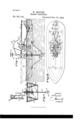
- Figure l is a partial side elevation and partial sectional view of the improved velocipede and life raft.
- Fig. '2 is a plan view thereof, and
- Fig. 3 is a vertical section taken essentially onthe line 3-3 of Fig. 1.
- the hull of the velocipede may be said to consist of two sections A and B, each section'being triangular in cross section, the widest at the top, and these hull sections are made to meet at what may be termed the bow of thevelocipede or life raft and separated below the bow, curving outwardly in opposite directions to a predetermined degree, and then extending in parallel lines sternward, being connected at the stern in any approved manner upon semi-circular lines; but the hull sections atthe stern are separated below what is intended to be the. water line, and each hull section at the stern is provided with the usual run or overhang.
- Each hull section is preferably made up of two walls, an inner wall 10 and an outer wall 11, the space between the two walls being filled with cork, or other buoyant material 12, as shown in Fig. 3.
- the hull sections are decked over by a platform 13, corresponding in general outline to the outline formed by the combined hull sections, and the said hull sections are connected at suitable intervals by arched braces 14, the bolts attached to said braces being usually carried through the hull sections, as is likewise shown in Fig. 3.
- the deck or platform la is provided at or near its center with an opening 15, which corresponds to the space between the parallel lines of the hull sections, and above this open ing 15 the riders seat 16 is supported by suitable braces or supports 17.
- BraceslS and 19 are extended from hull to hull, preferably near their keel portions, one of the braces being located well forward and the other well aft, or one brace at each side of the center ofthe hull.
- These braces are adapted to carry a center-board O, the said center-board consisting primarily of a bar or tube-of a flexible material, which bar or tube may be made of steel or the equivalent thereof,- and is passed through the sockets of the braces 18 and 19, having free movement therein.
- a weight 20, is loosely carried upon the cen: tral portion of the center-board O, and this weight is attached to the lower end of a rod 21, the lower portion of the said rod being threaded; and it is made to pass up through a correspondingly treated surface in a central brace 22, connecting the hull sections, as shown in Fig 1.
- the rod 21 is likewise carried upward through and beyond the deck 13, being made to terminate at its upper end in a hand wheel 23, or the equivalent thereof,'to facilitate its manipulation. It may here be remarked that the attachment between the rod 21 and the weight 20 is on the swivel order.
- the hand wheel 23, is within convenient reach of the operator when in position on the seat 16.
- a ferrule 24, is attached to the deck section of the vessel at that point through which the regulating rod 21 of the center-board passes, and the said ferrule is adapted to receive and constitute a guide fora sleeve 25, which sleeve extends above and below the ferrule, and is provided preferably with a flange 26 resting on the ferrule.
- a pulley 27 is secured in any approved manner, and at the upper end of the said sleeve ahand wheel 28, or its equivalent, is attached, whereby the pulley may be turned,it being understood that the regulating rod 21 of the center-board passes through the sleeve and through the pulley.
- the pulley 27, has attached to it the steering lines or chains 29, which lead aft and are attached to the rudder 30, said rudder being journaled centrally between the two hull sections at the stern, as shown in Figs. 1 and 2, a suitable hearing being provided at the lower end of the hull sections for that purpose.
- a propeller shaft 31 is journaled in suitable bearings located between the hull sections, and the said propeller shaft extends from the deck line at apoint near the center diagonally downward and sternward, passing out between the separate stern portions of the hull sections, and a propeller 32, which may be of any approved construction, is secured upon the end of this shaft, being located forward of the rudder.
- the hull sections near their center have attached to them upwardly extending arched braces 33, which braces support a sleeve 34, and in this sleeve, which is virtually abearing, a pedal shaft 35 is journaled, being provided at each end with a pedal 36 within convenient reach of the person stationed on the seat 16.
- the pedal shaft is provided with a beveled gear 37 secured thereto, which meshes with a beveled pinion 38, located on the propeller shaft, but it will be understood that the gear connection between the propeller shaft and the pedal shaft may be varied as circumstances may demand; and it is evident that by raising and lowering the regulating rod 21 of the center-board the velocipede or life raft may be made to draw more or less water, as may be found desirable, and that all of the operative parts of the vessel may be operated conveniently by the person located on the seat 16, and that owing to the catamaran shape of the hull it will be exceedingly steady even in rough water.
- Life lines 39 may be and preferably are, located along the outer side faces of the hull.
- a water velocipede and life raft the combination, with a hull of the catamaran order, the sections of the hull being connected at the bow and connected at the upper portion of the stern, a propeller shaft extending sternward between the hull sections, being provided at its outer end with a propeller, and a rudder journaled at the stern of the hull, of a pedal shaft, a gear connection be tween the pedal shaft and the propeller shaft, a center-board consisting of a bar or tube of pliable material, having its ends free to move in guides, a weight carried by the tube, a regulating rod connected with the weight and extending upward beyond the deck of the hull, a steering shaft provided with a pulley and steering lines attached to the said pulley and to the rudder, substantially as shown and described.
- a water velocipede or life raft the combination, with a hull of the catamaran order, the hull sections being united at the bow and at the upper portion of the stern, each hull section being triangular in cross section and comprising an inner and an outer wall and a filling of buoyant material between them, the deck being laid over the hull sections, a propeller shaft journaled between the hull sections, extending sternward beyond said sections and terminating in a propeller, a rudder journaled at the stern, and a seatsupported upon the deck, of a pedal shaft capable of operation from said seat, a gear connection between the propeller shaft and the pedal shaft, a center-board centrally located between the hull sections, being constructed of a pliable material having free but guided movement, a weight located upon the center-board near its center, a regulating rod capable of raising and lowering the center board, attached to the weight and carried up through the deck convenient to the seat, a sleeve held to turn around the
Landscapes
- Chemical & Material Sciences (AREA)
- Engineering & Computer Science (AREA)
- Combustion & Propulsion (AREA)
- Mechanical Engineering (AREA)
- Ocean & Marine Engineering (AREA)
- Toys (AREA)
Description
Patented Dc. 18, I894.
' INVENTOH B) I J i t ATTORNEYS.
WITNESSES:
n: nonms Perms co.. vnorauwoq msmncrou. 6:1.
UNITED STATES PATENT Urrrcn.
WILLIAMDRYDEN, or BROOKLYN, NEW YORK.
MARINE VELOCIPEDE.
SPECIFICATION forming part of Letters Iatent No. 531,104, dated December 18, 1894.
Application flied April 6, 1894. Serial No. 506,584. (No model.)
.To on whom it may concern:
Be it known that I, WILLIAM ,DRYDEN, of Brooklyn, in the county of Kings and State of New York, have invented a new and Improved Water-Velocipede and Life-Raft, of whlch the following is a full, clear, and exact description.
My invention relates to a water velocipede, capable of 'use as a life raft when required, and it has for its object to provide such a vessel with a simple and conveniently operated propelling mechanism, and a center board under the complete control of the manipulator or dr1ver of the vessel, and to provide a steer ing gear which may be as conveniently operated as the center board.
The invention consists in the novel construction and combination of the several parts, as will be hereinafter fully set forth and pointed outin the claims. I
Reference is to be had to the accompanying drawings, forminga part of this specification,
in which similar figures and letters of reference indicate corresponding parts in all the views.
Figure l is a partial side elevation and partial sectional view of the improved velocipede and life raft. Fig. '2 is a plan view thereof, and Fig. 3 is a vertical section taken essentially onthe line 3-3 of Fig. 1.
In carrying out the invention the hull of the velocipede may be said to consist of two sections A and B, each section'being triangular in cross section, the widest at the top, and these hull sections are made to meet at what may be termed the bow of thevelocipede or life raft and separated below the bow, curving outwardly in opposite directions to a predetermined degree, and then extending in parallel lines sternward, being connected at the stern in any approved manner upon semi-circular lines; but the hull sections atthe stern are separated below what is intended to be the. water line, and each hull section at the stern is provided with the usual run or overhang.
Each hull section is preferably made up of two walls, an inner wall 10 and an outer wall 11, the space between the two walls being filled with cork, or other buoyant material 12, as shown in Fig. 3. The hull sections are decked over by a platform 13, corresponding in general outline to the outline formed by the combined hull sections, and the said hull sections are connected at suitable intervals by arched braces 14, the bolts attached to said braces being usually carried through the hull sections, as is likewise shown in Fig. 3.
The deck or platform la, is provided at or near its center with an opening 15, which corresponds to the space between the parallel lines of the hull sections, and above this open ing 15 the riders seat 16 is supported by suitable braces or supports 17. BraceslS and 19 are extended from hull to hull, preferably near their keel portions, one of the braces being located well forward and the other well aft, or one brace at each side of the center ofthe hull. These braces are adapted to carry a center-board O, the said center-board consisting primarily of a bar or tube-of a flexible material, which bar or tube may be made of steel or the equivalent thereof,- and is passed through the sockets of the braces 18 and 19, having free movement therein.
A weight 20, is loosely carried upon the cen: tral portion of the center-board O, and this weight is attached to the lower end of a rod 21, the lower portion of the said rod being threaded; and it is made to pass up through a correspondingly treated surface in a central brace 22, connecting the hull sections, as shown in Fig 1. The rod 21 is likewise carried upward through and beyond the deck 13, being made to terminate at its upper end in a hand wheel 23, or the equivalent thereof,'to facilitate its manipulation. It may here be remarked that the attachment between the rod 21 and the weight 20 is on the swivel order. The hand wheel 23, is within convenient reach of the operator when in position on the seat 16. p v
A ferrule 24, is attached to the deck section of the vessel at that point through which the regulating rod 21 of the center-board passes, and the said ferrule is adapted to receive and constitute a guide fora sleeve 25, which sleeve extends above and below the ferrule, and is provided preferably with a flange 26 resting on the ferrule. At the lower end of the sleeve a pulley 27, is secured in any approved manner, and at the upper end of the said sleeve ahand wheel 28, or its equivalent, is attached, whereby the pulley may be turned,it being understood that the regulating rod 21 of the center-board passes through the sleeve and through the pulley. The pulley 27, has attached to it the steering lines or chains 29, which lead aft and are attached to the rudder 30, said rudder being journaled centrally between the two hull sections at the stern, as shown in Figs. 1 and 2, a suitable hearing being provided at the lower end of the hull sections for that purpose.
A propeller shaft 31, is journaled in suitable bearings located between the hull sections, and the said propeller shaft extends from the deck line at apoint near the center diagonally downward and sternward, passing out between the separate stern portions of the hull sections, and a propeller 32, which may be of any approved construction, is secured upon the end of this shaft, being located forward of the rudder.
The hull sections near their center have attached to them upwardly extending arched braces 33, which braces support a sleeve 34, and in this sleeve, which is virtually abearing, a pedal shaft 35 is journaled, being provided at each end with a pedal 36 within convenient reach of the person stationed on the seat 16. The pedal shaft is provided with a beveled gear 37 secured thereto, which meshes with a beveled pinion 38, located on the propeller shaft, but it will be understood that the gear connection between the propeller shaft and the pedal shaft may be varied as circumstances may demand; and it is evident that by raising and lowering the regulating rod 21 of the center-board the velocipede or life raft may be made to draw more or less water, as may be found desirable, and that all of the operative parts of the vessel may be operated conveniently by the person located on the seat 16, and that owing to the catamaran shape of the hull it will be exceedingly steady even in rough water. Life lines 39, may be and preferably are, located along the outer side faces of the hull.
Having thus described my invention, I claim as new and desire to secure by Letters Patent- 1. In a water velocipede or life raft, the combination with a hull of the catamaran order, the hull sections being united at the bow, of a propeller shaft, a propeller thereon, a seat for the operator, a pedal shaft capable of operation from said seat and in gear with the propeller shaft, a center board located between the hull sections, and a regulating rod connected with said center board and extending upward beyond the deck of the hull and adapted to be manipulated by the operator when in position on the seat, as and for the purpose set forth.
2. In a water velocipede and life raft, the combination, with a hull of the catamaran order, the sections of the hull being connected at the bow and connected at the upper portion of the stern, a propeller shaft extending sternward between the hull sections, being provided at its outer end with a propeller, and a rudder journaled at the stern of the hull, of a pedal shaft, a gear connection be tween the pedal shaft and the propeller shaft, a center-board consisting of a bar or tube of pliable material, having its ends free to move in guides, a weight carried by the tube, a regulating rod connected with the weight and extending upward beyond the deck of the hull, a steering shaft provided with a pulley and steering lines attached to the said pulley and to the rudder, substantially as shown and described.
3. In a water velocipede or life raft, the combination, with a hull of the catamaran order, the hull sections being united at the bow and at the upper portion of the stern, each hull section being triangular in cross section and comprising an inner and an outer wall and a filling of buoyant material between them, the deck being laid over the hull sections, a propeller shaft journaled between the hull sections, extending sternward beyond said sections and terminating in a propeller, a rudder journaled at the stern, and a seatsupported upon the deck, of a pedal shaft capable of operation from said seat, a gear connection between the propeller shaft and the pedal shaft, a center-board centrally located between the hull sections, being constructed of a pliable material having free but guided movement, a weight located upon the center-board near its center, a regulating rod capable of raising and lowering the center board, attached to the weight and carried up through the deck convenient to the seat, a sleeve held to turn around the regulating rod, a pulley attached to the lower end of the said sleeve, and steering lines attached to the said pulley and the rudder, as and for the purpose set forth.
WILLIAM DRYDEN.
Witnesses:
F. A. SANDS, J OSIE A. PAGE.
Publications (1)
| Publication Number | Publication Date |
|---|---|
| US531104A true US531104A (en) | 1894-12-18 |
Family
ID=2599883
Family Applications (1)
| Application Number | Title | Priority Date | Filing Date |
|---|---|---|---|
| US531104D Expired - Lifetime US531104A (en) | Marine velocipede |
Country Status (1)
| Country | Link |
|---|---|
| US (1) | US531104A (en) |
-
0
- US US531104D patent/US531104A/en not_active Expired - Lifetime
Similar Documents
| Publication | Publication Date | Title |
|---|---|---|
| US1204355A (en) | Motor-boat. | |
| US641321A (en) | Sailing vessel. | |
| US531104A (en) | Marine velocipede | |
| US545095A (en) | Apparatus for trimming ships | |
| US1054851A (en) | Life-boat. | |
| US1888443A (en) | Water craft | |
| US128407A (en) | Improvement in construction of vessels | |
| US596685A (en) | Foot-propelled boat | |
| US1041849A (en) | Motor-boat. | |
| US1336226A (en) | Sailboat | |
| US1165535A (en) | Submarine vessel. | |
| US131719A (en) | Improvement in life-saving apparatus | |
| US211807A (en) | Improvement in life-boats | |
| US1773210A (en) | Hydro-sporting machine | |
| US1318879A (en) | Safety swimming-cycle | |
| US1299476A (en) | Life-boat. | |
| US512186A (en) | Augustus w | |
| US607965A (en) | Boat-propelling mechanism | |
| US475420A (en) | James savage | |
| US147252A (en) | Improvement in apparatus for navigating the air | |
| US344623A (en) | Steering-gear for vessels | |
| US304742A (en) | Propulsion of boats | |
| US573690A (en) | Conrad odinet | |
| US59074A (en) | Improved portable propeller and steerer for boats | |
| US835800A (en) | Jury-rudder. |