US5305870A - Method of and apparatus for transporting loosely bound books - Google Patents

Method of and apparatus for transporting loosely bound books Download PDF

Info

Publication number
US5305870A
US5305870A US08/020,626 US2062693A US5305870A US 5305870 A US5305870 A US 5305870A US 2062693 A US2062693 A US 2062693A US 5305870 A US5305870 A US 5305870A
Authority
US
United States
Prior art keywords
projections
saddle plates
book
teeth
saddle
Prior art date
Legal status (The legal status is an assumption and is not a legal conclusion. Google has not performed a legal analysis and makes no representation as to the accuracy of the status listed.)
Expired - Fee Related
Application number
US08/020,626
Inventor
Manfred Riesmeier
Current Assignee (The listed assignees may be inaccurate. Google has not performed a legal analysis and makes no representation or warranty as to the accuracy of the list.)
Kolbus GmbH and Co KG
Original Assignee
Kolbus GmbH and Co KG
Priority date (The priority date is an assumption and is not a legal conclusion. Google has not performed a legal analysis and makes no representation as to the accuracy of the date listed.)
Filing date
Publication date
Application filed by Kolbus GmbH and Co KG filed Critical Kolbus GmbH and Co KG
Assigned to KOLBUS GMBH & CO. KG reassignment KOLBUS GMBH & CO. KG ASSIGNMENT OF ASSIGNORS INTEREST. Assignors: RIESMEIER, MANFRED
Application granted granted Critical
Publication of US5305870A publication Critical patent/US5305870A/en
Anticipated expiration legal-status Critical
Expired - Fee Related legal-status Critical Current

Links

Images

Classifications

    • B—PERFORMING OPERATIONS; TRANSPORTING
    • B42—BOOKBINDING; ALBUMS; FILES; SPECIAL PRINTED MATTER
    • B42C—BOOKBINDING
    • B42C11/00—Casing-in
    • B—PERFORMING OPERATIONS; TRANSPORTING
    • B42—BOOKBINDING; ALBUMS; FILES; SPECIAL PRINTED MATTER
    • B42B—PERMANENTLY ATTACHING TOGETHER SHEETS, QUIRES OR SIGNATURES OR PERMANENTLY ATTACHING OBJECTS THERETO
    • B42B9/00—Devices common to machines for carrying out the processes according to more than one of the preceding main groups
    • B42B9/04—Devices common to machines for carrying out the processes according to more than one of the preceding main groups for conveying downwardly-open signatures
    • B—PERFORMING OPERATIONS; TRANSPORTING
    • B42—BOOKBINDING; ALBUMS; FILES; SPECIAL PRINTED MATTER
    • B42C—BOOKBINDING
    • B42C19/00—Multi-step processes for making books
    • B42C19/08—Conveying between operating stations in machines
    • B—PERFORMING OPERATIONS; TRANSPORTING
    • B42—BOOKBINDING; ALBUMS; FILES; SPECIAL PRINTED MATTER
    • B42D—BOOKS; BOOK COVERS; LOOSE LEAVES; PRINTED MATTER CHARACTERISED BY IDENTIFICATION OR SECURITY FEATURES; PRINTED MATTER OF SPECIAL FORMAT OR STYLE NOT OTHERWISE PROVIDED FOR; DEVICES FOR USE THEREWITH AND NOT OTHERWISE PROVIDED FOR; MOVABLE-STRIP WRITING OR READING APPARATUS
    • B42D5/00—Sheets united without binding to form pads or blocks
    • B42D5/003—Note-pads
    • B42D5/008—Note-pads with means for engaging sheet perforations or slots
    • B—PERFORMING OPERATIONS; TRANSPORTING
    • B65—CONVEYING; PACKING; STORING; HANDLING THIN OR FILAMENTARY MATERIAL
    • B65H—HANDLING THIN OR FILAMENTARY MATERIAL, e.g. SHEETS, WEBS, CABLES
    • B65H2301/00—Handling processes for sheets or webs
    • B65H2301/30—Orientation, displacement, position of the handled material
    • B65H2301/32—Orientation of handled material
    • B65H2301/322—Riding over one elongated or saddle-like member
    • B65H2301/3221—Riding over one elongated or saddle-like member on saddle-like member extending perpendicularly to the transport direction
    • B—PERFORMING OPERATIONS; TRANSPORTING
    • B65—CONVEYING; PACKING; STORING; HANDLING THIN OR FILAMENTARY MATERIAL
    • B65H—HANDLING THIN OR FILAMENTARY MATERIAL, e.g. SHEETS, WEBS, CABLES
    • B65H2404/00—Parts for transporting or guiding the handled material
    • B65H2404/30—Chains
    • B65H2404/32—Saddle conveyor
    • B—PERFORMING OPERATIONS; TRANSPORTING
    • B65—CONVEYING; PACKING; STORING; HANDLING THIN OR FILAMENTARY MATERIAL
    • B65H—HANDLING THIN OR FILAMENTARY MATERIAL, e.g. SHEETS, WEBS, CABLES
    • B65H2701/00—Handled material; Storage means
    • B65H2701/10—Handled articles or webs
    • B65H2701/18—Form of handled article or web
    • B65H2701/182—Piled package
    • B65H2701/1829—Bound, bundled or stapled stacks or packages

Definitions

  • the present invention relates to the transporting of books during an intermediate stage of the production thereof and particularly to the conveying of batches of previously ordered paper sheets, the sheets being interconnected by mechanical binders, to a position where covers are applied thereto. More specifically, the present invention is directed to a conveyor mechanism which affords stable transport, to a cover application station, of batches of loose sheets which are retained in the order by means of mechanical binding elements. Accordingly, the general objects of the present invention are to provide novel and improved methods and apparatus of such character.
  • Each of these double rings at one end, has a short section of wire which extends diagonally with respect to the rings to interconnect the rings of each tooth.
  • a series of holes is punched in the batch of sheets, the teeth of the comb are passed through these holes, and the teeth are bent in the shape of a circle.
  • the tips of the teeth extend into facing interstices in the binder, these interstices being left as a result of the formation of the teeth, so as to define a discontinuous, generally linear seam.
  • Such a comb binding is indicated at 3 in application FIG. 1.
  • the binding element is fabricated from plastic and has a support section with teeth extending outwardly therefrom. After the teeth of such a plastic binding element have been inserted through the holes in the stacked sheets comprising the "book", the binding element is formed into a cylindrical shape and a seam is defined by abutting ends of cooperating teeth.
  • a conveyor in accordance with the present invention will include a significant number of saddle plates which are coupled to the endless chains of a rotary drive. These saddle plates are provided with positioning means that are sized and shaped to fit between the ring-like teeth of a mechanical binding element.
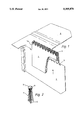
  • FIG. 1 is a partial perspective view of a conveyor in accordance with the invention, FIG. 1 depicting a saddle plate immediately prior to its engagement with a mechanically bound book;
  • FIG. 2 is an enlarged, partial cross-sectional view of the saddle plate of FIG. 1, FIG. 2 depicting the saddle plate in engagement with the bound batch of sheets comprising the book.
  • a batch of loose paper which defines an unfinished book is indicated at 1.
  • Each of the sheets of paper comprising the book 1 is provided, adjacent an edge, with a linear array of holes 1a.
  • the sheets comprising the book 1 are loosely bound together via the aligned arrays of holes by means of a mechanical binding element 3 which, in the disclosed embodiment, is a wire comb having teeth which define double rings.
  • the teeth of the binding element 3 are inserted through the holes 1a and subsequently bent into the circular shape which may be seen by joint consideration of FIGS. 1 and 2.
  • the conveying mechanism of the present invention comprises a rotary-driven conveyor having a large number of saddle plates 4 coupled to endless chains.
  • the saddle plates 4 are each provided with a serrated leading edge, indicated generally at 5, defined by a plurality of spatially displaced teeth. These teeth are sized and shaped to fit between the ring-shaped teeth of the comb-like binding element 3. Accordingly, when the saddle plate 4 moves upwardly into engagement with the book, as clearly shown in FIG. 2, the teeth of the serrated edge thereof will fit between the teeth of the binding element and the book will be securely and accurately transported so that it may be brought into precise alignment with the book cover 2.
  • the teeth provided in the leading edge of the saddle plates, in the edge region thereof which is inserted between the teeth of the binding element are generally wedge-shaped.
  • the side faces of the teeth on the saddle plate are angled so as to converge towards the tips thereof.
  • the ends or tips of the saddle plate teeth are rounded.

Landscapes

  • Basic Packing Technique (AREA)

Abstract

A conveyor for use with a machine which applies covers to books of the type where the individual pages are loosely bound by means of mechanical binder elements having rounded teeth. The conveyor includes multiple saddle plates, coupled to endless chains, which are caused to move into engagement with the bound batches of pages. The saddle plates are provided with serrated leading edge portions which fit between the teeth of the binding elements to accurately position the bound pages relative to the saddle plates.

Description

BACKGROUND OF THE INVENTION
1. Field of Invention
The present invention relates to the transporting of books during an intermediate stage of the production thereof and particularly to the conveying of batches of previously ordered paper sheets, the sheets being interconnected by mechanical binders, to a position where covers are applied thereto. More specifically, the present invention is directed to a conveyor mechanism which affords stable transport, to a cover application station, of batches of loose sheets which are retained in the order by means of mechanical binding elements. Accordingly, the general objects of the present invention are to provide novel and improved methods and apparatus of such character.
2. Description of the Prior Art
In the manufacture of books, conveyor mechanisms are employed to transport partially finished books between work stations. Often, as a book nears completion, the conveying thereof becomes more difficult. This is particularly true in the case of books that are comprised of loose sheets which are provided with a series of holes along one edge, the sheets being retained in prearranged order by means of generally round mechanical binding elements. Examples of "books" having such construction which must be transported to a cover application station are notebooks and calendars, such "books" often being provided with reinforced front and back end sheets. The binding elements employed in such "books" may be fabricated from wire or plastic. Thus, in the technique known in the trade as "comb" binding, a wire is formed into a linear array of parallel teeth, each tooth defining a double ring. Each of these double rings, at one end, has a short section of wire which extends diagonally with respect to the rings to interconnect the rings of each tooth. In the course of assembly of such a mechanically bound "book", a series of holes is punched in the batch of sheets, the teeth of the comb are passed through these holes, and the teeth are bent in the shape of a circle. The tips of the teeth extend into facing interstices in the binder, these interstices being left as a result of the formation of the teeth, so as to define a discontinuous, generally linear seam. Such a comb binding is indicated at 3 in application FIG. 1.
In accordance with an alternative mechanical binding technique, the binding element is fabricated from plastic and has a support section with teeth extending outwardly therefrom. After the teeth of such a plastic binding element have been inserted through the holes in the stacked sheets comprising the "book", the binding element is formed into a cylindrical shape and a seam is defined by abutting ends of cooperating teeth.
Batches of paper sheets held together by the above-described mechanical binding elements are often encased in a rigid book cover. This "casing-in" operation is performed by adhesively securing the end sheets of the "book" to the inside of the leaves of the book covers. In order to deliver the bound "book" to a casing-in machine, the "book" must be supported astride saddle plates of an endless conveyor. This, however, places the straight edge of the saddle plate under the round teeth of the binding element. The casing-in operation includes the application of paste to the end sheets of the "book" and the subsequent rolling of the cover onto the "book" by means of lateral pressure rollers. These rollers first move upwardly, while engaged with the cover, and then change direction and roll the book cover onto the "book".
The lack of stability of a mechanically bound "book" on a saddle plate presents a problem of long standing in the art. This problem manifests itself in the possibility of relative movement between the edge of the saddle plate and the round teeth of the binding element, any such movement resulting in the end sheets of the "book" not contacting the book cover at right angles or the lateral distances being uneven. Also, the binding elements often cannot be made parallel to the backs of the book covers. Any such misalignment results in an unacceptable product.
SUMMARY OF THE INVENTION
The present invention overcomes the above-briefly discussed and other deficiencies and disadvantages of the prior art by providing a novel and improved conveyor particularly well suited for use with a casing-in machine of a book production facility. A conveyor in accordance with the present invention will include a significant number of saddle plates which are coupled to the endless chains of a rotary drive. These saddle plates are provided with positioning means that are sized and shaped to fit between the ring-like teeth of a mechanical binding element.
BRIEF DESCRIPTION OF THE DRAWINGS
The present invention may be better understood and its numerous objects and advantages will become apparent to those skilled in the art by reference to the accompanying drawing wherein like reference numerals refer to like elements in the two figures and which:
FIG. 1 is a partial perspective view of a conveyor in accordance with the invention, FIG. 1 depicting a saddle plate immediately prior to its engagement with a mechanically bound book; and
FIG. 2 is an enlarged, partial cross-sectional view of the saddle plate of FIG. 1, FIG. 2 depicting the saddle plate in engagement with the bound batch of sheets comprising the book.
DESCRIPTION OF THE DISCLOSED EMBODIMENT
With reference now to the drawing, a batch of loose paper which defines an unfinished book is indicated at 1. Each of the sheets of paper comprising the book 1 is provided, adjacent an edge, with a linear array of holes 1a. The sheets comprising the book 1 are loosely bound together via the aligned arrays of holes by means of a mechanical binding element 3 which, in the disclosed embodiment, is a wire comb having teeth which define double rings. As briefly discussed above in the Description of the Prior Art, the teeth of the binding element 3 are inserted through the holes 1a and subsequently bent into the circular shape which may be seen by joint consideration of FIGS. 1 and 2.
The conveying mechanism of the present invention comprises a rotary-driven conveyor having a large number of saddle plates 4 coupled to endless chains. In accordance with the invention, the saddle plates 4 are each provided with a serrated leading edge, indicated generally at 5, defined by a plurality of spatially displaced teeth. These teeth are sized and shaped to fit between the ring-shaped teeth of the comb-like binding element 3. Accordingly, when the saddle plate 4 moves upwardly into engagement with the book, as clearly shown in FIG. 2, the teeth of the serrated edge thereof will fit between the teeth of the binding element and the book will be securely and accurately transported so that it may be brought into precise alignment with the book cover 2.
Also in accordance with the preferred embodiment, and as best seen from FIG. 2, the teeth provided in the leading edge of the saddle plates, in the edge region thereof which is inserted between the teeth of the binding element, are generally wedge-shaped. Thus, the side faces of the teeth on the saddle plate are angled so as to converge towards the tips thereof. Also, the ends or tips of the saddle plate teeth are rounded.
While a preferred embodiment has been shown and described, various modifications and substitutions may be made thereto without departing from the spirit and scope of the invention. Accordingly, it is to be understood that the present invention has been described by way of illustration and not limitation.
Claims (9)

What is claimed is:
1. In a conveyor for use with a casing-in machine of a book manufacturing operation, the conveyor having multiple saddle plates, the saddle plates intercepting books comprised of plural loose sheets, each sheet having an array of holes along one edge and the holes of all of the sheets being generally aligned, the loose sheets being retained in an assembled condition by a single mechanical binding member having plural curved teeth which extend through the aligned holes in the sheets, the improvement comprising:
positioning means on the leading edge of each of said saddle plates, said positioning means engaging a book in regions located between the teeth of the binding member whereby the possibility of relative movement between the saddle plate and book subsequent to such engagement is minimized.
2. The apparatus of claim 1 wherein said positioning means comprises a series of spaced projections in the leading edge of each of said saddle plates.
3. The apparatus of claim 2 wherein said projections are provided with rounded leading edges.
4. The apparatus of claim 2 wherein said projections are generally wedge-shaped.
5. The apparatus of claim 3 wherein said projections are generally wedge-shaped.
6. The apparatus of claim 2 wherein said projections are distributed over the entire length of each of said saddle plates.
7. The apparatus of claim 3 wherein said projections are distributed over the entire length of each of said saddle plates.
8. The apparatus of claim 4 wherein said projections are distributed over the entire length of each of said saddle plates.
9. The apparatus of claim 5 wherein said projections are distributed over the entire length of each of said saddle plates.
US08/020,626 1992-12-09 1993-02-22 Method of and apparatus for transporting loosely bound books Expired - Fee Related US5305870A (en)

Applications Claiming Priority (2)

Application Number Priority Date Filing Date Title
DE4241386A DE4241386A1 (en) 1992-12-09 1992-12-09 Book hanging machine
DE4241386 1992-12-09

Publications (1)

Publication Number Publication Date
US5305870A true US5305870A (en) 1994-04-26

Family

ID=6474730

Family Applications (1)

Application Number Title Priority Date Filing Date
US08/020,626 Expired - Fee Related US5305870A (en) 1992-12-09 1993-02-22 Method of and apparatus for transporting loosely bound books

Country Status (2)

Country Link
US (1) US5305870A (en)
DE (1) DE4241386A1 (en)

Cited By (2)

* Cited by examiner, † Cited by third party
Publication number Priority date Publication date Assignee Title
US20060278350A1 (en) * 2005-06-10 2006-12-14 Zamarripa Rosa M Device to repair vertical blinds
US20110014011A1 (en) * 2009-07-20 2011-01-20 Muller Martini Holding Ag Device for deforming a book cover aligned approximately on a book block back

Citations (3)

* Cited by examiner, † Cited by third party
Publication number Priority date Publication date Assignee Title
US4157821A (en) * 1976-11-26 1979-06-12 Womako-Maschinenkonstruktionen Gmbh Method and apparatus for manipulating marginally perforated note books prior to introduction of spirals
US4232858A (en) * 1968-10-09 1980-11-11 Womako Maschinenkonstruktionen Gmbh Method and means for manipulating marginally perforated note books prior to introduction of spirals
US4237568A (en) * 1978-01-28 1980-12-09 Bielomatik Leuze Gmbh & Co. Apparatus and method for the binding of stacks of sheets

Patent Citations (3)

* Cited by examiner, † Cited by third party
Publication number Priority date Publication date Assignee Title
US4232858A (en) * 1968-10-09 1980-11-11 Womako Maschinenkonstruktionen Gmbh Method and means for manipulating marginally perforated note books prior to introduction of spirals
US4157821A (en) * 1976-11-26 1979-06-12 Womako-Maschinenkonstruktionen Gmbh Method and apparatus for manipulating marginally perforated note books prior to introduction of spirals
US4237568A (en) * 1978-01-28 1980-12-09 Bielomatik Leuze Gmbh & Co. Apparatus and method for the binding of stacks of sheets

Cited By (2)

* Cited by examiner, † Cited by third party
Publication number Priority date Publication date Assignee Title
US20060278350A1 (en) * 2005-06-10 2006-12-14 Zamarripa Rosa M Device to repair vertical blinds
US20110014011A1 (en) * 2009-07-20 2011-01-20 Muller Martini Holding Ag Device for deforming a book cover aligned approximately on a book block back

Also Published As

Publication number Publication date
DE4241386A1 (en) 1994-06-16

Similar Documents

Publication Publication Date Title
US4365180A (en) Strip wound dynamoelectric machine core
US5108244A (en) Book production process and apparatus
DE69216881T2 (en) Sheet post-processing device
US4264663A (en) Laminated pack comprising a plurality of closely superposed sheets and method and device for forming the pack
DE3508416A1 (en) METHOD AND DEVICE FOR COLLATIONING SIGNATURES
CH677916A5 (en)
US2112389A (en) Sheet binder
CS208708B2 (en) Facility for feeding and cutting the sheet stack
EP0904870A3 (en) Plate for lead storage batteries and apparatus for manufacture thereof
US2185004A (en) Method of binding sheet material
DE2404667A1 (en) DIAL BINDING MACHINE
US4620724A (en) Binding strips for rectangular hole punched paper
US1741269A (en) Gluing mechanism for bookbinding machines
US4129913A (en) Arrangement for perforating and spiral binding of relatively thick groups of sheets
US4129156A (en) Method and construction for spiral wire binding of pads
US20250206058A1 (en) Bound collection of leaves featuring region of reduced cumulative leaf thickness
EP2474423A2 (en) Method and device for producing bound paper products
DE102008004434A1 (en) Method for operating a bookbinding machine
DE2435082C3 (en) Device for combining two sub-stacks consisting of signatures
US3427655A (en) Method for producing collated printed books
GB2028695A (en) Rotary stripper
KR20190067787A (en) Seat attachment device
US2246702A (en) Binder
US2973199A (en) Machine for manufacturing pads bound with a spiral wire
US6868872B2 (en) Apparatus for coupling stacked sheets

Legal Events

Date Code Title Description
AS Assignment

Owner name: KOLBUS GMBH & CO. KG, GERMANY

Free format text: ASSIGNMENT OF ASSIGNORS INTEREST.;ASSIGNOR:RIESMEIER, MANFRED;REEL/FRAME:006496/0815

Effective date: 19930323

FEPP Fee payment procedure

Free format text: PAYOR NUMBER ASSIGNED (ORIGINAL EVENT CODE: ASPN); ENTITY STATUS OF PATENT OWNER: LARGE ENTITY

FPAY Fee payment

Year of fee payment: 4

FPAY Fee payment

Year of fee payment: 8

REMI Maintenance fee reminder mailed
LAPS Lapse for failure to pay maintenance fees
STCH Information on status: patent discontinuation

Free format text: PATENT EXPIRED DUE TO NONPAYMENT OF MAINTENANCE FEES UNDER 37 CFR 1.362

FP Lapsed due to failure to pay maintenance fee

Effective date: 20060426