US5305646A - Gauge for compressible medium - Google Patents
Gauge for compressible medium Download PDFInfo
- Publication number
- US5305646A US5305646A US07/830,390 US83039092A US5305646A US 5305646 A US5305646 A US 5305646A US 83039092 A US83039092 A US 83039092A US 5305646 A US5305646 A US 5305646A
- Authority
- US
- United States
- Prior art keywords
- probe
- gauge
- movable
- compressible material
- cylinder
- Prior art date
- Legal status (The legal status is an assumption and is not a legal conclusion. Google has not performed a legal analysis and makes no representation as to the accuracy of the status listed.)
- Expired - Lifetime
Links
- 239000000463 material Substances 0.000 claims abstract description 68
- 239000000523 sample Substances 0.000 claims abstract description 48
- 210000005069 ears Anatomy 0.000 claims description 5
- 238000006073 displacement reaction Methods 0.000 claims 1
- 238000010276 construction Methods 0.000 abstract description 10
- 238000012360 testing method Methods 0.000 description 5
- 238000005259 measurement Methods 0.000 description 4
- 239000012530 fluid Substances 0.000 description 3
- 238000011144 upstream manufacturing Methods 0.000 description 2
- 238000004519 manufacturing process Methods 0.000 description 1
- 238000012986 modification Methods 0.000 description 1
- 230000004048 modification Effects 0.000 description 1
- 230000000737 periodic effect Effects 0.000 description 1
Images


Classifications
-
- G—PHYSICS
- G01—MEASURING; TESTING
- G01B—MEASURING LENGTH, THICKNESS OR SIMILAR LINEAR DIMENSIONS; MEASURING ANGLES; MEASURING AREAS; MEASURING IRREGULARITIES OF SURFACES OR CONTOURS
- G01B5/00—Measuring arrangements characterised by the use of mechanical techniques
- G01B5/30—Measuring arrangements characterised by the use of mechanical techniques for measuring the deformation in a solid, e.g. mechanical strain gauge
-
- G—PHYSICS
- G01—MEASURING; TESTING
- G01B—MEASURING LENGTH, THICKNESS OR SIMILAR LINEAR DIMENSIONS; MEASURING ANGLES; MEASURING AREAS; MEASURING IRREGULARITIES OF SURFACES OR CONTOURS
- G01B5/00—Measuring arrangements characterised by the use of mechanical techniques
- G01B5/02—Measuring arrangements characterised by the use of mechanical techniques for measuring length, width or thickness
- G01B5/06—Measuring arrangements characterised by the use of mechanical techniques for measuring length, width or thickness for measuring thickness
Definitions
- This invention relates to testing compressible material.
- Various gauges are known in the prior art for measuring the thickness of a compressible material, such as a gasket material.
- One prior art gauge utilizes a weight that forces a probe into the compressible material.
- a sensor measures the amount of deformation of the compressible material due to the weight. The measured deformation is compared to an expected deformation to provide an indication whether the compressible material is of the proper thickness and construction. While the prior art gauge has proven relatively promising in accurately testing a compressible medium, it would be desirable to improve its construction.
- the known gauge involves placing a weight at a location in the center of the gauge, but the structure of the known gauge does not ensure that the weight is accurately centered on the gauge. This may result in the weight not producing proper amount of deformation and the test giving inaccurate results. Further, the prior art gauge is allowed to fall freely under the influence of the weight. If the gauge falls at a rate outside of a predetermined range, it may not cause the proper amount of deformation.
- a gauge in a disclosed embodiment, includes a cylinder which holds a bracket at a first vertical position.
- a movable probe is attached to the bracket, and is spaced from a fixed probe by a predetermined distance when the gauge is held at the first vertical position by the cylinder.
- a predetermined weight is attached to the bracket.
- a compressible material such as gasket material, is placed between the movable and fixed probes, and the cylinder is opened such that a piston within the cylinder falls. The cylinder no longer holds the bracket and movable probe at the first vertical position, but allows them to fall downwardly onto-the gasket material.
- the cylinder provides a damper force limiting the speed of downward movement of the bracket and movable probe as they fall.
- the movable probe contacts the gasket material and causes some measurable deformation.
- An electronic sensor measures the amount of deformation due to the predetermined weight. The measured deformation is compared to an expected deformation to provide an indication whether the thickness and construction of the gasket material is proper. If the thickness or construction is improper the measured deformation will be different than the expected deformation.
- the weight is attached to the bracket at lateral positions equally spaced about a center axis of the bracket.
- the movable and fixed probes are aligned on the center axis. The weight is thus applied to the compressible material directly along the axis of the movable probe, and accurate results are obtained.
- a plurality of such gauges are spaced laterally across the gasket material, and may also be movable longitudinally with a moving gasket material.
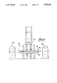
- FIG. 1 is a perspective view of a first embodiment gauge according to the present invention.
- FIG. 2 is a front view of the gauge illustrated in FIG. 1.
- FIG. 3 is a partial side view of the gauge illustrated in FIG. 1.
- FIG. 4A is a cross-sectional view through a portion of the gauge illustrated in FIG. 3.
- FIG. 4B is a view similar to FIG. 4A.
- FIG. 5 is an enlarged view of a portion of the present invention.
- FIG. 6 is a cross-sectional view along line 6--6 as shown in FIG. 4A.
- FIG. 7 is a cross-sectional view along line 7--7 as shown in FIG. 4A.
- FIG. 8 is a perspective view of a second embodiment of the present invention.
- FIG. 9 is a cross-sectional view along line 9--9 as shown in FIG. 8.
- FIG. 10 is a perspective view of a third embodiment of the present invention.
- FIG. 11 is a cross-sectional view along line 11--11 as shown in FIG. 10.
- FIG. 12 is a cross-sectional view through the third embodiment gauge.
- a gauge 20 for testing a gasket material 22 is illustrated in FIG. 1.
- a platform 24 supports gasket material 22, and a movable upper probe 26 is brought into contact with gasket material 22.
- Upper probe 26 is fixed to a movable rail 28 which is slidably supported in a bearing 30.
- a housing 32 slidably supports a bracket 34 which is fixed to movable rail 28.
- a pair of laterally spaced weights 36 are mounted on each lateral side of bracket 34, such that the weights are equally spaced about a center axis of movable rail 28 and probe 26.
- a cylinder 38 is fixed to a top end of bracket 34, and a fluid line 40 controls fluid within cylinder 38.
- a piston (not shown in this figure) is held stationary within cylinder 38 and maintains bracket 34 at a fixed vertical position.
- Cylinder 38 can drain, and the piston falls. Consequently, bracket 34, weights 36, movable rail 28 and upper probe 26 all fall towards gasket material 22.
- Cylinder 38 may be a pneumatic cylinder.
- Upper probe 26 falls until it contacts gasket material 22.
- the weights 36 then cause some deformation of gasket material 22 by upper probe 26.
- An electronic sensor 41 determines the amount of deformation of gasket material 22 due to the predetermined weight applied from weights 36.
- An expected amount of deformation for a gasket material 22 having the appropriate thickness and construction is known.
- the amount of expected deformation for the predetermined weight is compared with the amount of measured deformation to provide an indication of whether gasket material 22 is of proper thickness and construction.
- the weights 36 have mounting ears 42 and are mounted at lateral sides of bracket 34.
- a lower probe 44 is received beneath platform 24, such that it extends slightly above the surface of platform 24. In one preferred embodiment, lower probe 44 extends 0.004 inch above platform 24. The position of lower probe 44 is adjustable within a threaded bore within platform 24.
- Upper probe 26 is coaxial with lower probe 44, such that gasket material 22 is pinched between probes 26 and 44.
- the weights 36 are evenly spaced about the axis of probe 26 and, consequently, probe 44, such that the weight is evenly distributed.
- Bearings 46 support bracket 34 at a vertically upper position. Movable rail 28 is supported at a vertically lower position by bearings 30. Bearings 46 and 30 ensure the movement of bracket 34 and rail 28 is directly vertically downwardly. If the movement of the members were at an angle to a vertical axis, the amount of deformation measured by electronic sensor 41 might not be a true indication of the amount of deformation of the gasket material 22.
- FIG. 3 is a side view of gauge 20, and shows keyhole shaped slots 48 in the bracket 34 which receive ears 42 of weights 36.
- Keyhole shaped slots 48 have an enlarged upper portion and a smaller lower portion. Ears 42 are inserted into the enlarged upper portion and moved downwardly into the smaller lower portion to secure weights 36 to bracket 34. This facilitates the attachment of weights 36 to bracket 34, such that the weight may be easily replaced to vary the loads applied to a particular gasket material 22.
- pneumatic cylinder 38 includes a piston 50 having an enlarged member, such as a nut 51, received on a lower vertical side of a bracket upper portion 52. Piston 50 is biased into cylinder 38, such that it retains bracket portion 52 at a desired vertical position. In this position upper probe 26 is spaced from gasket material 22. A lower tip 53 of electronic sensor 41 extends into contact with a lower bracket surface 55. The position of lower tip 53 gives an indication to electronic sensor 41 that lower bracket surface 55 is spaced from electronic sensor 41 by a distance d 1 .
- bracket 34 When cylinder 38 is open, is no positive connection between piston 50 and bracket portion 52. Thus, should piston 50 continue to fall after gasket material 22 resists further deformation due to weights 36, bracket 34 would not also move further vertically downwardly. Pneumatic cylinder 38 and piston 50 act as a damper to slow the descent of bracket 34 and probe 26, but do not apply any force to cause downward vertical movement. Such a force could cause inaccuracies in the measured deformation of gasket material 22.
- ears 42 are attached to weights 36, and may be moved into keyhole shape slots 48. This facilitates the easy attachment of weights 36 onto the lateral sides of bracket 34, and allows an operator to quickly change the applied weight.
- movable rail 28 is mounted between two bearings 30. Bearings 30 positively guide and support movable rail 28 for vertical movement.
- rail 45 is fixed to a rear portion of bracket 34 and received between bearings 46. Bearings 46 provide guidance and support for rail 45, and bracket 34.
- FIG. 8 is a perspective view of a second embodiment gauge system 60 according to the present invention.
- Gauge system 60 has two laterally spaced gauges 62, each of which are similar in construction to gauge 20.
- Gauges 62 have lines 64 leading to pneumatic cylinders 66 which are automatically opened, such that gauges 62 operate automatically in response to control signals.
- the control signals to open lines 64 may be actuated in response to the movement of a predetermined amount of movement of gasket material 70, such that gauge system 60 makes periodic measurements of gasket material 70.
- Gauges 62 are mounted by brackets 65 on track 67. Brackets 65 contain bolts that may be loosened such that the lateral positions of gauges 62 may be adjusted. In this way, an operator may vary the lateral positions at which gasket material 70 is measured.
- a press structure 68 ensures that the gasket material 70 moving into the area adjacent gauges 62 has a predetermined tension. The deformation due to a particular weight is thus more consistent.
- press structure 68 includes a piston 71 which forces a top plate 72 vertically downwardly towards a bottom plate 74.
- Plates 72 and 74 have a central space, such that the probes may move through the central space to contact gasket material 70.
- Rollers 75 are associated with bottom plate 74 both upstream and downstream of bottom plate 74.
- FIG. 10 is a perspective view of a third embodiment gauge system 80 according to the present invention.
- a gasket material 82 is measured as it moves along a longitudinal direction. The gasket material can thus be tested as it is formed, without stopping the gasket material or a production line.
- a pair of end gauges 84, and a center gauge 86 test gasket material 82 at three laterally spaced locations.
- Gauges 84 and 86 are mounted on a lateral track 88 such that their lateral positions may be adjusted.
- a mount 89 mounts all three gauges 84 and 86, and lateral track 88, and moves longitudinally along rail structure 90. Blocks 91 guide mount 89 on rail structure 90. Gauges 84 and 86 may thus move longitudinally along with gasket material 82.
- a press structure 92 secures the gauges and mount 89 to the gasket material and also ensures that the tension in gasket material 82 is as desired when the measurements are performed.
- press structure 92 is engaged and mount 89 and the gauges are pulled longitudinally along with gasket material 82.
- Gauges 84 and 86 measure the deformation due to a particular weight on gasket material 82.
- mount 89 is reciprocated back to a starting position, where the gauge system 80 may make a new measurement of subsequent gasket material 82.
- a pneumatic cylinder drives mount 89 back to the starting position. More preferably, a rodless cylinder rail is used to drive mount 89.
- press structure 92 has spaced plates 94 and 96.
- a cylinder 98 forces plate 94 into contact with the gasket material 82 when gauges 84 and 86 are being used.
- a pair of spaced roller stations 100 (not shown in FIG. 10) ensure that the tension in the material 82 is as desired at positions upstream and downstream from plates 94 and 96 when plate 94 is not forced downwardly. This ensures that plate 94 will not damage gasket material 82 when the gauges 84 and 80 are not being used.
- FIG. 12 shows probes 102 extending from gauges 84 and 86.
- the probes 102 are spaced across the lateral width of gauge system 80.
- the weight is preferably varied for different gasket materials.
- An operator experimentally determines an expected amount of deformation for a particular gasket material and weight. The actual measured deformation is then compared to this expected deformation to determine whether a particular gasket material has been properly manufactured.
- the electronic sensor used was a Mitutoyo Digimatic Indicator, model 543-380, and was AC powered.
Landscapes
- Physics & Mathematics (AREA)
- General Physics & Mathematics (AREA)
- A Measuring Device Byusing Mechanical Method (AREA)
- Investigating Strength Of Materials By Application Of Mechanical Stress (AREA)
- Length Measuring Devices With Unspecified Measuring Means (AREA)
Abstract
Description
Claims (5)
Priority Applications (3)
| Application Number | Priority Date | Filing Date | Title |
|---|---|---|---|
| US07/830,390 US5305646A (en) | 1992-02-03 | 1992-02-03 | Gauge for compressible medium |
| CA002087935A CA2087935A1 (en) | 1992-02-03 | 1993-01-22 | Gauge for compressible medium |
| MX9300542A MX9300542A (en) | 1992-02-03 | 1993-02-01 | CALIBRATOR FOR COMPRESSIBLE MEDIA. |
Applications Claiming Priority (1)
| Application Number | Priority Date | Filing Date | Title |
|---|---|---|---|
| US07/830,390 US5305646A (en) | 1992-02-03 | 1992-02-03 | Gauge for compressible medium |
Publications (1)
| Publication Number | Publication Date |
|---|---|
| US5305646A true US5305646A (en) | 1994-04-26 |
Family
ID=25256903
Family Applications (1)
| Application Number | Title | Priority Date | Filing Date |
|---|---|---|---|
| US07/830,390 Expired - Lifetime US5305646A (en) | 1992-02-03 | 1992-02-03 | Gauge for compressible medium |
Country Status (3)
| Country | Link |
|---|---|
| US (1) | US5305646A (en) |
| CA (1) | CA2087935A1 (en) |
| MX (1) | MX9300542A (en) |
Cited By (11)
| Publication number | Priority date | Publication date | Assignee | Title |
|---|---|---|---|---|
| RU2160440C2 (en) * | 1999-02-01 | 2000-12-10 | Самарский государственный технический университет | Procedure determining mechanical characteristics of structural materials and gear for its realization |
| EP1296137A3 (en) * | 2001-09-25 | 2003-04-09 | A. FRITSCH GMBH & CO. KG | Dough measurement for monitoring and controlling the dough quality in automatic dough processing |
| US6857322B2 (en) * | 2000-04-07 | 2005-02-22 | Bp Chemicals Limited | Method for measuring compressibility during a polymerization process |
| US20070006664A1 (en) * | 2005-07-08 | 2007-01-11 | Certainteed Corporation | Method and apparatus for determining insulation thickness |
| US20130042705A1 (en) * | 2011-02-16 | 2013-02-21 | Thomastik-Infeld Gesellschaft M.B.H. | Measuring apparatus |
| US8474323B1 (en) | 2009-09-01 | 2013-07-02 | Honda Motor Co., Ltd. | Carpet deflection measurement device |
| CN103557780A (en) * | 2013-10-29 | 2014-02-05 | 上海电气电站设备有限公司 | Motor parallel connection ring lead fixing tightness detection method |
| EP2905573A1 (en) * | 2014-02-07 | 2015-08-12 | Helmut Fischer GmbH | Method for electrically controlling a gauge stand and gauge stand for holding a measurement gauge |
| CN108225241A (en) * | 2017-12-19 | 2018-06-29 | 来安县祥瑞机电科技有限责任公司 | A kind of mobile phone screen tempered glass film thickness detection device |
| CN110658061A (en) * | 2019-10-29 | 2020-01-07 | 四川九天真空科技有限公司 | Elastic sealing ring compression force value measuring device |
| CN115014303A (en) * | 2022-07-21 | 2022-09-06 | 湖南城建职业技术学院 | A building interior surveying and mapping device |
Families Citing this family (3)
| Publication number | Priority date | Publication date | Assignee | Title |
|---|---|---|---|---|
| CN106643406B (en) * | 2016-11-23 | 2019-05-31 | 宁波昌隆机电有限公司 | A kind of elevator bank door head detection device |
| CN111623681A (en) * | 2019-02-27 | 2020-09-04 | 上海汽车集团股份有限公司 | Dislocation detection device and method for vehicle door buffer block structure |
| CN110206711B (en) * | 2019-04-26 | 2020-06-09 | 浙江大学 | Selection system and method for valve plate gasket of crank-link refrigerator compressor |
Citations (14)
| Publication number | Priority date | Publication date | Assignee | Title |
|---|---|---|---|---|
| US1723404A (en) * | 1927-06-24 | 1929-08-06 | Firestone Tire & Rubber Co | Extensometer mounting |
| US2282904A (en) * | 1940-03-18 | 1942-05-12 | Insulation Dev Corp | Durometer |
| US2376814A (en) * | 1943-08-27 | 1945-05-22 | Robinson Aviat Inc | Compression indicator |
| US2474118A (en) * | 1945-10-30 | 1949-06-21 | Robinson Aviat Inc | Compression testing apparatus |
| US2703492A (en) * | 1952-04-19 | 1955-03-08 | Gen Motors Corp | Compression tester |
| US2891399A (en) * | 1957-02-06 | 1959-06-23 | Rufolo Anthony | Device for measuring creep |
| US3618369A (en) * | 1970-04-21 | 1971-11-09 | Lawrence Mfg Co | Apparatus and method for testing rock |
| US3630074A (en) * | 1969-03-20 | 1971-12-28 | Res Derivatives Inc | Rate control for tools |
| US3750467A (en) * | 1971-11-03 | 1973-08-07 | Gonzalez R Barrera | Device to measure compressibility of soft materials |
| US4331026A (en) * | 1980-07-14 | 1982-05-25 | The Boeing Company | Indenter-type hardness testing apparatus |
| US4505278A (en) * | 1983-04-18 | 1985-03-19 | Alban Eugene P | Pain threshold gage and softness tester |
| US4578868A (en) * | 1983-04-01 | 1986-04-01 | Mitutoyo Mfg. Co., Ltd. | Digital display measuring apparatus |
| US4616508A (en) * | 1983-02-28 | 1986-10-14 | Georg Fischer Aktiengesellschaft | Method and apparatus for producing a test piece of molding compound useful in measuring properties thereof |
| US4709584A (en) * | 1986-10-15 | 1987-12-01 | Institut Khimii An | Device for taking samples of bottom sediments from water basins |
-
1992
- 1992-02-03 US US07/830,390 patent/US5305646A/en not_active Expired - Lifetime
-
1993
- 1993-01-22 CA CA002087935A patent/CA2087935A1/en not_active Abandoned
- 1993-02-01 MX MX9300542A patent/MX9300542A/en unknown
Patent Citations (14)
| Publication number | Priority date | Publication date | Assignee | Title |
|---|---|---|---|---|
| US1723404A (en) * | 1927-06-24 | 1929-08-06 | Firestone Tire & Rubber Co | Extensometer mounting |
| US2282904A (en) * | 1940-03-18 | 1942-05-12 | Insulation Dev Corp | Durometer |
| US2376814A (en) * | 1943-08-27 | 1945-05-22 | Robinson Aviat Inc | Compression indicator |
| US2474118A (en) * | 1945-10-30 | 1949-06-21 | Robinson Aviat Inc | Compression testing apparatus |
| US2703492A (en) * | 1952-04-19 | 1955-03-08 | Gen Motors Corp | Compression tester |
| US2891399A (en) * | 1957-02-06 | 1959-06-23 | Rufolo Anthony | Device for measuring creep |
| US3630074A (en) * | 1969-03-20 | 1971-12-28 | Res Derivatives Inc | Rate control for tools |
| US3618369A (en) * | 1970-04-21 | 1971-11-09 | Lawrence Mfg Co | Apparatus and method for testing rock |
| US3750467A (en) * | 1971-11-03 | 1973-08-07 | Gonzalez R Barrera | Device to measure compressibility of soft materials |
| US4331026A (en) * | 1980-07-14 | 1982-05-25 | The Boeing Company | Indenter-type hardness testing apparatus |
| US4616508A (en) * | 1983-02-28 | 1986-10-14 | Georg Fischer Aktiengesellschaft | Method and apparatus for producing a test piece of molding compound useful in measuring properties thereof |
| US4578868A (en) * | 1983-04-01 | 1986-04-01 | Mitutoyo Mfg. Co., Ltd. | Digital display measuring apparatus |
| US4505278A (en) * | 1983-04-18 | 1985-03-19 | Alban Eugene P | Pain threshold gage and softness tester |
| US4709584A (en) * | 1986-10-15 | 1987-12-01 | Institut Khimii An | Device for taking samples of bottom sediments from water basins |
Cited By (20)
| Publication number | Priority date | Publication date | Assignee | Title |
|---|---|---|---|---|
| RU2160440C2 (en) * | 1999-02-01 | 2000-12-10 | Самарский государственный технический университет | Procedure determining mechanical characteristics of structural materials and gear for its realization |
| US6857322B2 (en) * | 2000-04-07 | 2005-02-22 | Bp Chemicals Limited | Method for measuring compressibility during a polymerization process |
| EP1296137A3 (en) * | 2001-09-25 | 2003-04-09 | A. FRITSCH GMBH & CO. KG | Dough measurement for monitoring and controlling the dough quality in automatic dough processing |
| US20070006664A1 (en) * | 2005-07-08 | 2007-01-11 | Certainteed Corporation | Method and apparatus for determining insulation thickness |
| US7370538B2 (en) * | 2005-07-08 | 2008-05-13 | Certainteed Corporation | Method and apparatus for determining insulation thickness |
| US8474323B1 (en) | 2009-09-01 | 2013-07-02 | Honda Motor Co., Ltd. | Carpet deflection measurement device |
| US20130042705A1 (en) * | 2011-02-16 | 2013-02-21 | Thomastik-Infeld Gesellschaft M.B.H. | Measuring apparatus |
| CN103557780A (en) * | 2013-10-29 | 2014-02-05 | 上海电气电站设备有限公司 | Motor parallel connection ring lead fixing tightness detection method |
| CN103557780B (en) * | 2013-10-29 | 2016-08-17 | 上海电气电站设备有限公司 | A kind of fixing tightness detection method of motor parallel ring lead-in wire |
| US20150226586A1 (en) * | 2014-02-07 | 2015-08-13 | Helmut Fischer | Method for electronically activating a measurement stand, and measurement stand for supporting a measuring probe |
| CN104833299A (en) * | 2014-02-07 | 2015-08-12 | 赫尔穆特费希尔有限责任公司电子及测量技术研究所 | Method for electrically controlling a gauge stand and gauge stand for holding a measurement gauge |
| DE102014101577A1 (en) * | 2014-02-07 | 2015-08-13 | Helmut Fischer GmbH Institut für Elektronik und Messtechnik | Method for the electrical control of a measuring stand and measuring stand for receiving a measuring probe |
| JP2015148613A (en) * | 2014-02-07 | 2015-08-20 | ヘルムート・フィッシャー・ゲーエムベーハー・インスティテュート・フューア・エレクトロニク・ウント・メステクニク | Method for electrically actuating measurement stand and measurement stand for holding measurement probe |
| EP2905573A1 (en) * | 2014-02-07 | 2015-08-12 | Helmut Fischer GmbH | Method for electrically controlling a gauge stand and gauge stand for holding a measurement gauge |
| US9772205B2 (en) * | 2014-02-07 | 2017-09-26 | Helmut Fischer GmbH Institut für Elektronik und Messtechnik | Method for electronically activating a measurement stand, and measurement stand for supporting a measuring probe |
| CN108225241A (en) * | 2017-12-19 | 2018-06-29 | 来安县祥瑞机电科技有限责任公司 | A kind of mobile phone screen tempered glass film thickness detection device |
| CN108225241B (en) * | 2017-12-19 | 2019-11-12 | 徐州诚凯知识产权服务有限公司 | A mobile phone screen toughened glass film thickness detection device |
| CN110658061A (en) * | 2019-10-29 | 2020-01-07 | 四川九天真空科技有限公司 | Elastic sealing ring compression force value measuring device |
| CN115014303A (en) * | 2022-07-21 | 2022-09-06 | 湖南城建职业技术学院 | A building interior surveying and mapping device |
| CN115014303B (en) * | 2022-07-21 | 2023-08-01 | 湖南城建职业技术学院 | Indoor mapping device of building |
Also Published As
| Publication number | Publication date |
|---|---|
| CA2087935A1 (en) | 1993-08-04 |
| MX9300542A (en) | 1993-08-01 |
Similar Documents
| Publication | Publication Date | Title |
|---|---|---|
| US5305646A (en) | Gauge for compressible medium | |
| BR0115406A (en) | Device and method for calibrating a multi-roll player | |
| KR970000373B1 (en) | Automatic adjusting of an universal mill stand after its resetting for new structual shapes | |
| CZ263697A3 (en) | Process and apparatus for measuring tensile strength, elasticity, hardness, thickness or the like properties of a moving belt-like material such as a slag wool band | |
| US3127765A (en) | Consolidation and shear test apparatus | |
| CN214309991U (en) | Sampling and testing equipment for production and processing of plastic granules | |
| CN219434831U (en) | Anti sagging performance detection device of gypsum plasters | |
| US4375131A (en) | Vehicle frame datum line reference system | |
| KR100958989B1 (en) | Friction Coefficient Tester | |
| US3738151A (en) | Strip load simulator for shape-measuring roll | |
| CN113280723A (en) | Track roughness detects auxiliary platform | |
| CN218098691U (en) | Bending pressure monitoring device for structure | |
| GB451607A (en) | Continuous thickness gauging means | |
| CN214334638U (en) | Experimental pressure device of bituminous paving coefficient of friction | |
| CN212179789U (en) | A new contact type concrete shrinkage test measuring device | |
| US3363320A (en) | Can bead depth gauge | |
| CN208350031U (en) | A kind of high-speed train body side wall type face automatic detection device | |
| US2352571A (en) | Thickness-measuring apparatus | |
| CN217325537U (en) | Building foundation static load test detection device | |
| JPS6021761Y2 (en) | Workpiece transfer amount measuring device | |
| CN219455752U (en) | Tension detection mechanism convenient to fixed film | |
| CN211552647U (en) | Concrete test block size measuring device | |
| CN223021830U (en) | Auxiliary device for calibrating clamping force of cupping tester | |
| CN224066525U (en) | A prestress testing device for building steel structures | |
| CN215064311U (en) | Strain gauge calibration device |
Legal Events
| Date | Code | Title | Description |
|---|---|---|---|
| AS | Assignment |
Owner name: DANA CORPORATION, OHIO Free format text: ASSIGNMENT OF ASSIGNORS INTEREST.;ASSIGNOR:LAWSON, TOMMY K.;REEL/FRAME:006003/0992 Effective date: 19920103 Owner name: DANA CORPORATION, OHIO Free format text: ASSIGNMENT OF ASSIGNORS INTEREST.;ASSIGNOR:ASHMORE, JAMES D.;REEL/FRAME:006003/0990 Effective date: 19920115 |
|
| STCF | Information on status: patent grant |
Free format text: PATENTED CASE |
|
| CC | Certificate of correction | ||
| FPAY | Fee payment |
Year of fee payment: 4 |
|
| FEPP | Fee payment procedure |
Free format text: PAYOR NUMBER ASSIGNED (ORIGINAL EVENT CODE: ASPN); ENTITY STATUS OF PATENT OWNER: LARGE ENTITY |
|
| FPAY | Fee payment |
Year of fee payment: 8 |
|
| FPAY | Fee payment |
Year of fee payment: 12 |
|
| AS | Assignment |
Owner name: DANA AUTOMOTIVE SYSTEMS GROUP, LLC, OHIO Free format text: ASSIGNMENT OF ASSIGNORS INTEREST;ASSIGNOR:DANA CORPORATION;REEL/FRAME:020540/0476 Effective date: 20080131 Owner name: DANA AUTOMOTIVE SYSTEMS GROUP, LLC,OHIO Free format text: ASSIGNMENT OF ASSIGNORS INTEREST;ASSIGNOR:DANA CORPORATION;REEL/FRAME:020540/0476 Effective date: 20080131 |
|
| AS | Assignment |
Owner name: CITICORP USA, INC., NEW YORK Free format text: INTELLECTUAL PROPERTY REVOLVING FACILITY SECURITY AGREEMENT;ASSIGNORS:DANA HOLDING CORPORATION;DANA LIMITED;DANA AUTOMOTIVE SYSTEMS GROUP, LLC;AND OTHERS;REEL/FRAME:020859/0249 Effective date: 20080131 Owner name: CITICORP USA, INC.,NEW YORK Free format text: INTELLECTUAL PROPERTY REVOLVING FACILITY SECURITY AGREEMENT;ASSIGNORS:DANA HOLDING CORPORATION;DANA LIMITED;DANA AUTOMOTIVE SYSTEMS GROUP, LLC;AND OTHERS;REEL/FRAME:020859/0249 Effective date: 20080131 Owner name: CITICORP USA, INC., NEW YORK Free format text: INTELLECTUAL PROPERTY TERM FACILITY SECURITY AGREEMENT;ASSIGNORS:DANA HOLDING CORPORATION;DANA LIMITED;DANA AUTOMOTIVE SYSTEMS GROUP, LLC;AND OTHERS;REEL/FRAME:020859/0359 Effective date: 20080131 Owner name: CITICORP USA, INC.,NEW YORK Free format text: INTELLECTUAL PROPERTY TERM FACILITY SECURITY AGREEMENT;ASSIGNORS:DANA HOLDING CORPORATION;DANA LIMITED;DANA AUTOMOTIVE SYSTEMS GROUP, LLC;AND OTHERS;REEL/FRAME:020859/0359 Effective date: 20080131 |