US529842A - sceultz - Google Patents
sceultz Download PDFInfo
- Publication number
- US529842A US529842A US529842DA US529842A US 529842 A US529842 A US 529842A US 529842D A US529842D A US 529842DA US 529842 A US529842 A US 529842A
- Authority
- US
- United States
- Prior art keywords
- trough
- clutch
- machine
- troughs
- series
- Prior art date
- Legal status (The legal status is an assumption and is not a legal conclusion. Google has not performed a legal analysis and makes no representation as to the accuracy of the status listed.)
- Expired - Lifetime
Links
- GXCLVBGFBYZDAG-UHFFFAOYSA-N N-[2-(1H-indol-3-yl)ethyl]-N-methylprop-2-en-1-amine Chemical compound CN(CCC1=CNC2=C1C=CC=C2)CC=C GXCLVBGFBYZDAG-UHFFFAOYSA-N 0.000 description 6
- 238000004890 malting Methods 0.000 description 6
- 230000007246 mechanism Effects 0.000 description 4
- 238000007599 discharging Methods 0.000 description 3
- 238000001035 drying Methods 0.000 description 3
- 230000035784 germination Effects 0.000 description 2
- 239000011521 glass Substances 0.000 description 2
- 239000002184 metal Substances 0.000 description 2
- ORILYTVJVMAKLC-UHFFFAOYSA-N Adamantane Natural products C1C(C2)CC3CC1CC2C3 ORILYTVJVMAKLC-UHFFFAOYSA-N 0.000 description 1
- 238000010276 construction Methods 0.000 description 1
- 230000010006 flight Effects 0.000 description 1
- 230000000266 injurious effect Effects 0.000 description 1
- 230000033001 locomotion Effects 0.000 description 1
- 238000004519 manufacturing process Methods 0.000 description 1
- 239000000463 material Substances 0.000 description 1
- 239000007787 solid Substances 0.000 description 1
Images
Classifications
-
- B—PERFORMING OPERATIONS; TRANSPORTING
- B65—CONVEYING; PACKING; STORING; HANDLING THIN OR FILAMENTARY MATERIAL
- B65G—TRANSPORT OR STORAGE DEVICES, e.g. CONVEYORS FOR LOADING OR TIPPING, SHOP CONVEYOR SYSTEMS OR PNEUMATIC TUBE CONVEYORS
- B65G33/00—Screw or rotary spiral conveyors
Definitions
- ADAM SCHULTZ or CINCINNATI, OHIO, ASSIGNOR or ONE-HALF TO JOHN DECK, on SAME PLACE.
- my invention relates to an entirely new class of machines for the production of malt whereby I am enabled to handle the grain in continuous and large quantities first to produce the malt and after-' ward to dry it in another machine having the; principal characteristics of the first read y for use in brewing or mash making.
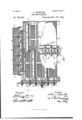
- Sheet 1 is a side elevation partly in section of a machine embodying my invention.
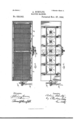
- Fig. 2 Sheet 2 is a plan view of the machine of Fig. 1.
- Fig. 3, Sheet 2 is a sectional plan.
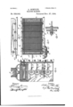
- Fig. 4 Sheet 3 is an end elevation of the machine partlyin section looking from the left of Figs. 1, 2 and 3.
- Fig. 5 Sheet 3 is an enlarged plan View partly in section of one of the movable troughs and associated mechanisms.
- Fig. 6, Sheet 3 is a side elevation of Fig. 5, omitting the driving mechanism.
- Fig. 7, Sheet 3 is an enlarged sectional detail of one of the clutch mechanisms.
- any suitable rectangular frame work I mount a series of horizontal troughs, A, A A A and so on, whose length is slightly greater than the length of half of the frame work as seen in Fig. 1.
- These troughs are in layers, one above the other and in the initial position of rest the trough A is-in the top line to the'right.
- the trough A is in the second line to the left.
- the trough A is in the third line to the right and so on down through the series.
- the trough A has its end at the center of the frame work closed and its opposite end open and this is true of the other troughs of the series when they occupy the positions shown in Fig. l.
- each trough is composed of glass or enameled tiling, while for the drying of the germinated-malt the'bottoms of the troughs are of wire gauze or perforated metal.
- Each trough is supportedon pivoted rollers a which travel on the side rails 11 of the frame work, as shown, and mounted in each trough is a discharging rake composed of a shaft 0 journaled transversely at each end of the trough and carrying sprocket wheels d over which pass drive chains e to which are secured transverse raking bars f Fig. 1.
- Upon the end of the shaft 0 at the open end of the trough is one part h of a clutch.
- a vertical train work'of'intermeshing gears B B, B B and so on one for each trough and mounted loosely on a screw shaft C, O, 0 (Band (3 respectively.
- the screw shafts are suitably journaled longitudinally of the frame work and at the middle of the troughs, and each engages a nut 21 on the under side of its trough.
- Feathered on the outer endofeach of the screw shafts is one part j of a clutch which is adapted to engage a similar part of a clutch'on'the hub or face of the gears B, B, B and so on, and these clutches are thrown into or out of engagement by pivoted hand levers D, Figs.
- gears 8 5 B, B', and so on Any suitable means may be employed for driving the gears 8 5 B, B', and so on, and in this instance I have shown them driven from a worm shaft E, whose worm 70 engages a worm-wheel l on the hub of the gear B.
- Extending over the top of the frame is a series of steeping vats or bins 1, Figs. 1, 2 and 4, opening by means of suitable gates into a conveyer trough J, containing a conveyer shaft driven by the gear B and having two flights of conveyers K, L extending under the vats and both discharging at the center of the machine into a transverse right and left conveyer M whose trough has an opening at its bottom extending its entire length.
- the conveyer M is driven by a gear F meshing with the train of gears F, F and so on.
- the operation of the machine thus constructed to secure the germination of the grain is as follows:
- the grain is properly steeped in the vats I, each of which contains just a sufficient charge for one trough and is discharged by the conveyers K, L and M evenly into the trough A.
- the clutchj of screw shaft 0 is thrown into engagement with the gear 13 thereby locking the shaft to said gear which, acting on the nut 41 of the trough A draws it slowly to the left so that the grain is deposited to an even depth the whole length and width of the trough.
- trough A will be directly over trough A and the clutch h of the rake mechanism will be opposite the clutch m.
- trough A is set in motion slowly to the right and clutch m is thrown into engagement with clutch h of trough A, thereby starting the rake of said trough into operation which gradually feeds out the contents of trough A into trough A
- Any suitable fan not shown is employed to force out the impure air. Whenever any trough is emptied it is shifted back to its original position by reversing the direction of revolution of the gears B, B and so on in any suitable manner.
- the ma chine For drying the germinated malt, the ma chine has to be cased in and the floors of-the troughs, instead of being solid and of glass or equivalent material are of woven wire or perforated metal, and heated air is drawn through the machine in any suitable way to dry the malt. In all other respects, the construction and mode of operation are the same. Instead of screw shafts for operating the troughs any other suitable means might be employed.
- the malt is discharged from the lowermost trough into a conveyer box provided with a suitable conveyer for taking it away from the machine.
- I claim- 1 In a malting machine, the combination of a series of horizontally movable troughs, means for operating the same, and a horizontally revoluble discharge rake for each trough carried thereby and arranged to discharge its contents into the next lower trough as the latter moves under its open end, substantially as described.
- ADAM SCHULTZ ADAM SCHULTZ.
Landscapes
- Engineering & Computer Science (AREA)
- Mechanical Engineering (AREA)
- Drying Of Solid Materials (AREA)
Description
a sheets -sneet 1.
(No Model.)
A SCHULTZ MALTING MAGHINE. No. 529,842. Patented Nov. 27, 1894.
B. W M W 3 Sheets-Sheet 3.
(No Model.) A. SCHULTZ.
MALTING MAGHINE.
No. 529,842. Patented Nov. 27, 1894.
llllllllllllllllllll IUI llllllllllllllllllll ilNiTED ST TES PATENT OFFICE.
ADAM SCHULTZ, or CINCINNATI, OHIO, ASSIGNOR or ONE-HALF TO JOHN DECK, on SAME PLACE.
MALTING- MACHINE.
SPECIFICATION forming part of Letters Patent No. 529,842, dated November 27, 1894.
Application filedAugnst '7 1393. Serial No. 482,599- (lTo model.) i
To all whom it may concern-.-
Be it known that I, ADAM SCHULTZ, a citizen of the United States, residing at Cincin nati, in the county of Hamilton and State of Ohio, have invented certain new and useful Improvements in Malting and Malt-Drying Machines, of which the following is a full,- clear, and exact description, reference being had to the accompanying drawings, forming part of this specification.
So far as I am aware, my invention relates to an entirely new class of machines for the production of malt whereby I am enabled to handle the grain in continuous and large quantities first to produce the malt and after-' ward to dry it in another machine having the; principal characteristics of the first read y for use in brewing or mash making.
The novelty of my invention will be herelnafter set forth and specifically pointed outi in the claims.
In the accompanying drawings :Figure 1,
Sheet 1, is a side elevation partly in section of a machine embodying my invention. Fig. 2, Sheet 2, is a plan view of the machine of Fig. 1. Fig. 3, Sheet 2, is a sectional plan.
view on the dotted line a: a; of Fig. 1. Fig. 4, Sheet 3, is an end elevation of the machine partlyin section looking from the left of Figs. 1, 2 and 3. Fig. 5 Sheet 3, is an enlarged plan View partly in section of one of the movable troughs and associated mechanisms. Fig. 6, Sheet 3, is a side elevation of Fig. 5, omitting the driving mechanism. Fig. 7, Sheet 3, is an enlarged sectional detail of one of the clutch mechanisms.
The same letters of reference are used to indicate identical parts in all the figures.
In any suitable rectangular frame work I mount a series of horizontal troughs, A, A A A and so on, whose length is slightly greater than the length of half of the frame work as seen in Fig. 1. These troughs are in layers, one above the other and in the initial position of rest the trough A is-in the top line to the'right. The trough A is in the second line to the left. The trough A is in the third line to the right and so on down through the series. The trough A, has its end at the center of the frame work closed and its opposite end open and this is true of the other troughs of the series when they occupy the positions shown in Fig. l.
Forthe germination of the malt the bottom of each trough is composed of glass or enameled tiling, while for the drying of the germinated-malt the'bottoms of the troughs are of wire gauze or perforated metal. Each trough is supportedon pivoted rollers a which travel on the side rails 11 of the frame work, as shown, and mounted in each trough is a discharging rake composed of a shaft 0 journaled transversely at each end of the trough and carrying sprocket wheels d over which pass drive chains e to which are secured transverse raking bars f Fig. 1. Upon the end of the shaft 0 at the open end of the trough is one part h of a clutch. Upon one end of the framework of the machine is a vertical train work'of'intermeshing gears B B, B B and so on, one for each trough and mounted loosely on a screw shaft C, O, 0 (Band (3 respectively. The screw shafts are suitably journaled longitudinally of the frame work and at the middle of the troughs, and each engages a nut 21 on the under side of its trough. Feathered on the outer endofeach of the screw shafts is one part j of a clutch which is adapted to engage a similar part of a clutch'on'the hub or face of the gears B, B, B and so on, and these clutches are thrown into or out of engagement by pivoted hand levers D, Figs. 2, 3 and 4., having forked ends engaging circumferential grooves in thefeathered clutch parts j. Any suitable means may be employed for driving the gears 8 5 B, B', and so on, and in this instance I have shown them driven from a worm shaft E, whose worm 70 engages a worm-wheel l on the hub of the gear B.
On one side of the frame work at the mido dle is a similar train of intermeshing gears F, F, F and so on, feathered on stub shafts G, G, G and so on, whose inner ends have fast thereon one partm of a clutch to engage the other part It on the shaft 0 of the adjacent 5 trough, while their outer ends have circumferentially grooved collars n engaged by the forked ends of pivoted hand levers H for sliding the stub shafts in or out to engage or disengage the clutch parts to and h.
Extending over the top of the frame is a series of steeping vats or bins 1, Figs. 1, 2 and 4, opening by means of suitable gates into a conveyer trough J, containing a conveyer shaft driven by the gear B and having two flights of conveyers K, L extending under the vats and both discharging at the center of the machine into a transverse right and left conveyer M whose trough has an opening at its bottom extending its entire length. The conveyer M is driven by a gear F meshing with the train of gears F, F and so on.
The operation of the machine thus constructed to secure the germination of the grain is as follows: The grain is properly steeped in the vats I, each of which contains just a sufficient charge for one trough and is discharged by the conveyers K, L and M evenly into the trough A. As soon as the conveyers begin to discharge the grain the clutchj of screw shaft 0 is thrown into engagement with the gear 13 thereby locking the shaft to said gear which, acting on the nut 41 of the trough A draws it slowly to the left so that the grain is deposited to an even depth the whole length and width of the trough. When this action has taken place, trough A will be directly over trough A and the clutch h of the rake mechanism will be opposite the clutch m. After the grain has remained a sufficient time upon the floor of trough A, trough A is set in motion slowly to the right and clutch m is thrown into engagement with clutch h of trough A, thereby starting the rake of said trough into operation which gradually feeds out the contents of trough A into trough A In like manner the remaining troughs are operated to convey the germinating grain from the top to the bottom of the machine without the necessity of injurious handling and enabling a large quantity to be worked in a short time. Any suitable fan, not shown is employed to force out the impure air. Whenever any trough is emptied it is shifted back to its original position by reversing the direction of revolution of the gears B, B and so on in any suitable manner.
For drying the germinated malt, the ma chine has to be cased in and the floors of-the troughs, instead of being solid and of glass or equivalent material are of woven wire or perforated metal, and heated air is drawn through the machine in any suitable way to dry the malt. In all other respects, the construction and mode of operation are the same. Instead of screw shafts for operating the troughs any other suitable means might be employed. The malt is discharged from the lowermost trough into a conveyer box provided with a suitable conveyer for taking it away from the machine.
Having thus fully described my invention, I claim- 1. In a malting machine, the combination of a series of horizontally movable troughs, means for operating the same, anda horizontally revoluble discharge rake for each trough carried thereby and arranged to discharge its contents into the next lower trough as the latter moves under its open end, substantially as described.
2. In a malting machine, the combination of a series of vats or bins, a double conveyer extending longitudinally of the same, a transverse conveyer at the middle of the former, a series of horizontal movable troughs beneath said conveyers, means for operating the same, and a discharge rake for each trough,
substantially as described.
3. In a malting machine, the combination of a series of horizontal movable troughs, rotary discharging rakes for each trough each provided with one part of a clutch, and a series of sliding clutches any one of which is adapted to be engaged with the clutch of. its adjacent rake when the trough is in proper position, substantially as described.
ADAM SCHULTZ.
lVitnesses:
J. THOMSON ORoss, BERNARD J. HAUSFELD.
Publications (1)
| Publication Number | Publication Date |
|---|---|
| US529842A true US529842A (en) | 1894-11-27 |
Family
ID=2598624
Family Applications (1)
| Application Number | Title | Priority Date | Filing Date |
|---|---|---|---|
| US529842D Expired - Lifetime US529842A (en) | sceultz |
Country Status (1)
| Country | Link |
|---|---|
| US (1) | US529842A (en) |
Cited By (3)
| Publication number | Priority date | Publication date | Assignee | Title |
|---|---|---|---|---|
| US2558155A (en) * | 1948-03-31 | 1951-06-26 | Poupart Max Jean | Plant for the continuous zymothermic fermentation of all organic matters |
| US2770575A (en) * | 1952-02-11 | 1956-11-13 | Lyons & Co Ltd J | Production of bacterial enzyme preparations and the cultivation of microorganism of industrial and nutritional value |
| US4363571A (en) * | 1980-04-04 | 1982-12-14 | United Conveyor Corporation | System for feeding pulverulent material into a pressurized air conveyor pipeline |
-
0
- US US529842D patent/US529842A/en not_active Expired - Lifetime
Cited By (3)
| Publication number | Priority date | Publication date | Assignee | Title |
|---|---|---|---|---|
| US2558155A (en) * | 1948-03-31 | 1951-06-26 | Poupart Max Jean | Plant for the continuous zymothermic fermentation of all organic matters |
| US2770575A (en) * | 1952-02-11 | 1956-11-13 | Lyons & Co Ltd J | Production of bacterial enzyme preparations and the cultivation of microorganism of industrial and nutritional value |
| US4363571A (en) * | 1980-04-04 | 1982-12-14 | United Conveyor Corporation | System for feeding pulverulent material into a pressurized air conveyor pipeline |
Similar Documents
| Publication | Publication Date | Title |
|---|---|---|
| US529842A (en) | sceultz | |
| US481958A (en) | Fourth to george c | |
| US1178674A (en) | Conveyer. | |
| US573500A (en) | woodman | |
| US236677A (en) | Grain-drier | |
| US1070296A (en) | Apparatus for emptying acid-phosphate chambers. | |
| US2443296A (en) | Ramie harvesting and decorticating machine | |
| US97038A (en) | Improvement in machinery for manufacturing semohna and flour | |
| US845744A (en) | Machine for cleansing filter-beds. | |
| US299297A (en) | van winkle | |
| US1239399A (en) | Coating-machine. | |
| US1669526A (en) | Cake-mold-filling machine | |
| US1909586A (en) | Bronze colors polishing machine | |
| US1221A (en) | Machine fob making and baking biscuits and crackers | |
| US899507A (en) | Apparatus for roasting and briqueting ores. | |
| US1778389A (en) | Mechanism for making concrete pipe | |
| US1158848A (en) | Conveyer. | |
| US1345715A (en) | Crushing-machine | |
| US889606A (en) | Blending-machine. | |
| US297517A (en) | haldane | |
| US966869A (en) | Washing apparatus. | |
| US573727A (en) | Washirjgtos | |
| US495389A (en) | hillingk | |
| US35271A (en) | Improvement in stirring, conveying, and cooling grain | |
| US778458A (en) | Centrifugal machine. |