US529634A - James bernard sweeney and robert wallace laird - Google Patents
James bernard sweeney and robert wallace laird Download PDFInfo
- Publication number
- US529634A US529634A US529634DA US529634A US 529634 A US529634 A US 529634A US 529634D A US529634D A US 529634DA US 529634 A US529634 A US 529634A
- Authority
- US
- United States
- Prior art keywords
- helve
- laird
- sweeney
- spring
- hammer
- Prior art date
- Legal status (The legal status is an assumption and is not a legal conclusion. Google has not performed a legal analysis and makes no representation as to the accuracy of the status listed.)
- Expired - Lifetime
Links
- 230000008878 coupling Effects 0.000 description 3
- 238000010168 coupling process Methods 0.000 description 3
- 238000005859 coupling reaction Methods 0.000 description 3
- 230000001105 regulatory effect Effects 0.000 description 2
- 238000005452 bending Methods 0.000 description 1
- 238000010276 construction Methods 0.000 description 1
- 238000004519 manufacturing process Methods 0.000 description 1
- 238000004088 simulation Methods 0.000 description 1
Images
Classifications
-
- B—PERFORMING OPERATIONS; TRANSPORTING
- B21—MECHANICAL METAL-WORKING WITHOUT ESSENTIALLY REMOVING MATERIAL; PUNCHING METAL
- B21D—WORKING OR PROCESSING OF SHEET METAL OR METAL TUBES, RODS OR PROFILES WITHOUT ESSENTIALLY REMOVING MATERIAL; PUNCHING METAL
- B21D1/00—Straightening, restoring form or removing local distortions of sheet metal or specific articles made therefrom; Stretching sheet metal combined with rolling
- B21D1/06—Removing local distortions
Definitions
- Our invention relates to improvements in that class of power hammers which are adaptio ed to deliver an elastic blow in simulation of the action of a hand hammer; and the object of our invention is to produce a very simple and efficient hammer of this kind, in which the vertically reciprocating hammer head is actuated bya tilting helve, the hammer head and helve being connected by a built -up spring formed of contiguous parallel plates, so that by using more or less plates the spring may be more or less resilient, and to provide zo a simple and easily operated means of driving and adjusting the helve so asto give a powerful blow and just the requisite stroke.
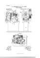
- FIG. 1 is a broken sectional elevation of the hammer embodying our invention.
- Fig. 2 is avfront view of the same; and
- Fig. 3 is a plan view of the same.
- the hammer is provided with a suitable frame 10, which is recessed in the usual way in front, as shown at 1011, to4 make room for handling material being hammered and also to form the table 11, in which is mounted an 4o anvil 12, the anvil being dovetailed in' the table, as shown in Fig. l, and above the anvil is the vertically reciprocating head 13 which has a die block or hammer face 14 dovetailed into its lower end, the die corresponding to the 45 anvil below it, as the drawings show.
- the head 13 is providedwith lateral 4verti cal flanges 15 which are adapted to move in ways formed between the removable plates 5a 16 and the front fiat face 17 of the main frame.
- the upper end of the head 13 is recessed, as shown at 19, the recess extending through the head from front to back and having curved upper and lower walls to provide for the easy 5 5 bending of the spring 20 by which the head is moved, this spring extending through the recess 19 and being held between blocks 2l which are preferably yielding.
- the spring 2O is made up of a series of plates laid one on 6o the other and in this way, by using more or less of the plates, the spring may be given any desired stiffness according to the nature of the work which is to be done.
- the rear end of the spring entersa slot 22 in the front 65 end of the tilting helve 23, this helve being preferably made in two pieces having a cap 24 at the front end forming the top half of the helve, the cap 24 being secured in place by'bolts 25 and 26, the former extending 7o through the rear nend of the spring 20, so as to bind the latter to the helve. It will thus be seen that when the helve tilts, it will impart a vertical motion to the head 13, and the spring does not bind as it is capable of slid- 7 5 ing longitudinally between the blocks 2l.
- the helve is fulcrumed near itsv center on the power shaft 27, which is provided with a pulley 28 or equivalent means for driving it, and in the center of the shaft is an eccentric 8o 29 moving in the split central portion 23a of the helve, the eccentric carrying a pitman 30 which extends downward and is, at its lower end, pivoted to the frontend of a rocking le-- ver 31, which is journaled on a shaft 32 near 85 the'back of the machine frame, and the rear end of the rocking lever is pivoted, as shown at 33 to a screw 34 which connects by a screw coupling 35 with a screw 36, this being piv-A oted at its upper end to a clip 37, which is 9o movable in a longitudinal slot 38 in the rear end of the helve 23 and is bound in place by a nut 39.
- the screws 34 and 36 have opposite pitch
- the screws and coupling thus form a connecting rod uniting the lever 31 and the helve and, by adjusting the length of the connecting rod, the depression of the head at each stroke, or the distance from the anvil at which this motion will be checked to suit different thicknesses of articles under treatment, may be regulated, while by adjusting the clip or block 37 the length of the stroke may be varied.
- a power hammer comprising a tilting helve split at its front end, a reciprocating head arranged adjacent to the helve and provided with a recess having curved upper and lower walls, a pair of binding blocks in the recess, and a spring held in the split end of the helve and projecting between the binding blocks, substantially as described.
- a power hammer comprising a tilting helve, a reciprocating head arranged adjacent to the helve and provided with a recess hav ing curved upper and lower Walls, a pair of yielding binding blocks in the recess and a ⁇ spring secured to the helve and projecting A between the binding blocks, substantially as described.
Landscapes
- Engineering & Computer Science (AREA)
- Mechanical Engineering (AREA)
- Portable Nailing Machines And Staplers (AREA)
Description
(No Model.) v
J. B. SWEENEY & B.. W. LAIRD.
' POWER HAMMER.
gygll. l Patented Nov. .20, 1894.
w/TNESSES.- v v /NVENTOHS 1 im ms M Arma/VHS.
UNITED STATES PATENT OFFICE.
JAMES BERNARD SWEENEY AND ROBERT WALLACE LAIRD, OF ST. JOHNS- BURY, VERMONT, ASSIGNORS TO THE LAIRD da SWEENEY MANUFACTUR- ING COMPANY, OF SAME PLACE. l
POWER-HAM M ER.
SPECIFICATION forming pare of Letters Patent No. 529,634, dated November 20,1894.
Application iiledMarch 3, 1 894. Serial No. 502,220. (No model.)
To @ZL whom it may concern.-
Beit known that we, JAMES BERNARD SWEE- NEY and ROBERT WALLACE LAIRD, both of St. Johnsbury, in the county of Caledonia and State of Vermont, have invented ,a new and Improved Power-Hammer, of which the following is a full, clear, and exact description. Our invention relates to improvements in that class of power hammers which are adaptio ed to deliver an elastic blow in simulation of the action of a hand hammer; and the object of our invention is to produce a very simple and efficient hammer of this kind, in which the vertically reciprocating hammer head is actuated bya tilting helve, the hammer head and helve being connected by a built -up spring formed of contiguous parallel plates, so that by using more or less plates the spring may be more or less resilient, and to provide zo a simple and easily operated means of driving and adjusting the helve so asto give a powerful blow and just the requisite stroke.
To these ends our invention consists of certain features of construction and combina- 2 5 tions of parts, which will be hereinafter described and claimed.
Reference is to be had to the accompanying drawings, forming a part of this specification, in which similar figures of reference indicate 3o corresponding parts in all the views.
Figure 1 is a broken sectional elevation of the hammer embodying our invention. Fig. 2 is avfront view of the same; and Fig. 3 is a plan view of the same. l 35 The hammer is provided with a suitable frame 10, which is recessed in the usual way in front, as shown at 1011, to4 make room for handling material being hammered and also to form the table 11, in which is mounted an 4o anvil 12, the anvil being dovetailed in' the table, as shown in Fig. l, and above the anvil is the vertically reciprocating head 13 which has a die block or hammer face 14 dovetailed into its lower end, the die corresponding to the 45 anvil below it, as the drawings show. These' above described features are not claimed asv novel.
The head 13 is providedwith lateral 4verti cal flanges 15 which are adapted to move in ways formed between the removable plates 5a 16 and the front fiat face 17 of the main frame.
The upper end of the head 13 is recessed, as shown at 19, the recess extending through the head from front to back and having curved upper and lower walls to provide for the easy 5 5 bending of the spring 20 by which the head is moved, this spring extending through the recess 19 and being held between blocks 2l which are preferably yielding. The spring 2O is made up of a series of plates laid one on 6o the other and in this way, by using more or less of the plates, the spring may be given any desired stiffness according to the nature of the work which is to be done. The rear end of the spring entersa slot 22 in the front 65 end of the tilting helve 23, this helve being preferably made in two pieces having a cap 24 at the front end forming the top half of the helve, the cap 24 being secured in place by'bolts 25 and 26, the former extending 7o through the rear nend of the spring 20, so as to bind the latter to the helve. It will thus be seen that when the helve tilts, it will impart a vertical motion to the head 13, and the spring does not bind as it is capable of slid- 7 5 ing longitudinally between the blocks 2l.
The helve is fulcrumed near itsv center on the power shaft 27, which is provided with a pulley 28 or equivalent means for driving it, and in the center of the shaft is an eccentric 8o 29 moving in the split central portion 23a of the helve, the eccentric carrying a pitman 30 which extends downward and is, at its lower end, pivoted to the frontend of a rocking le-- ver 31, which is journaled on a shaft 32 near 85 the'back of the machine frame, and the rear end of the rocking lever is pivoted, as shown at 33 to a screw 34 which connects by a screw coupling 35 with a screw 36, this being piv-A oted at its upper end to a clip 37, which is 9o movable in a longitudinal slot 38 in the rear end of the helve 23 and is bound in place by a nut 39. Y
The screws 34 and 36 have opposite pitch,
so that'by turning the coupling 35, the dis-1 95 l tance between the rear end of the helve and the rear end of the rocking lever 3l may be regulated. The screws and coupling thus form a connecting rod uniting the lever 31 and the helve and, by adjusting the length of the connecting rod, the depression of the head at each stroke, or the distance from the anvil at which this motion will be checked to suit different thicknesses of articles under treatment, may be regulated, while by adjusting the clip or block 37 the length of the stroke may be varied.
It will be seen that when the shaft 27 is revolved the ptman 30 will be moved up and down by its eccentric, the lever 3l will be tilted and, by means of the connecting rod, will impart an oscillating movement to the helve 23 which, by reason of its spring connection described, reciprocates the head 13,
and the material to be hammered is, of course,
placed in the usual Way upon the anvil beneath the face of the hammer head.
Having thus described our invention, We claim as new and desire to secure by Letters Patent- 1. A power hammer, comprising a tilting helve split at its front end, a reciprocating head arranged adjacent to the helve and provided with a recess having curved upper and lower walls, a pair of binding blocks in the recess, and a spring held in the split end of the helve and projecting between the binding blocks, substantially as described.
2. A power hammer, comprising a tilting helve, a reciprocating head arranged adjacent to the helve and provided with a recess hav ing curved upper and lower Walls, a pair of yielding binding blocks in the recess and a `spring secured to the helve and projecting A between the binding blocks, substantially as described.
JAMES BERNARD SWEENEY.
ROBERT WALLACE LAIRD.
Witnesses:
H. W. ALLEN, C. W. RINTER.
Publications (1)
| Publication Number | Publication Date |
|---|---|
| US529634A true US529634A (en) | 1894-11-20 |
Family
ID=2598416
Family Applications (1)
| Application Number | Title | Priority Date | Filing Date |
|---|---|---|---|
| US529634D Expired - Lifetime US529634A (en) | James bernard sweeney and robert wallace laird |
Country Status (1)
| Country | Link |
|---|---|
| US (1) | US529634A (en) |
-
0
- US US529634D patent/US529634A/en not_active Expired - Lifetime
Similar Documents
| Publication | Publication Date | Title |
|---|---|---|
| US529634A (en) | James bernard sweeney and robert wallace laird | |
| US314221A (en) | Cyeus m | |
| US53940A (en) | Iiviproved stone-dressing ivlachine | |
| US522701A (en) | Johan m | |
| US152106A (en) | Improvement in machines for cutting and bending metal bars | |
| US52215A (en) | Improvement in wood-splitting machines | |
| US365517A (en) | Machine for cutting metal | |
| US422918A (en) | Wire-nail machine | |
| US152416A (en) | Improvement in machines for bending car-braces | |
| US1007258A (en) | Staple forming and clenching machine. | |
| US656106A (en) | Metal-punch. | |
| US513933A (en) | Punching-machine | |
| US125423A (en) | Improvement in machines for making horseshoe-nails | |
| US1063640A (en) | Flasher. | |
| US774791A (en) | Power-hammer. | |
| US58520A (en) | whittemore | |
| US940608A (en) | Pipe-riveting machine. | |
| US115868A (en) | Improvement in combined machines for cutting, punching, and bending tires | |
| US630041A (en) | Power-hammer. | |
| US779721A (en) | Reciprocating hammer. | |
| US194675A (en) | Improvement in machines for bending metal bars | |
| US102731A (en) | Improved machine for making plows | |
| US429950A (en) | Wire nail machine | |
| US299502A (en) | Punc hing and shearing machine | |
| US498752A (en) | Power-hammer |