US5294082A - Spatula holder - Google Patents
Spatula holder Download PDFInfo
- Publication number
- US5294082A US5294082A US07/915,518 US91551892A US5294082A US 5294082 A US5294082 A US 5294082A US 91551892 A US91551892 A US 91551892A US 5294082 A US5294082 A US 5294082A
- Authority
- US
- United States
- Prior art keywords
- spatula
- mounting part
- mounting
- holder
- fold
- Prior art date
- Legal status (The legal status is an assumption and is not a legal conclusion. Google has not performed a legal analysis and makes no representation as to the accuracy of the status listed.)
- Expired - Lifetime
Links
- 238000004140 cleaning Methods 0.000 description 8
- 238000010411 cooking Methods 0.000 description 8
- 206010071232 Protuberant ear Diseases 0.000 description 7
- 239000000779 smoke Substances 0.000 description 7
- 239000003517 fume Substances 0.000 description 6
- 210000005069 ears Anatomy 0.000 description 4
- 230000000717 retained effect Effects 0.000 description 3
- 238000010276 construction Methods 0.000 description 2
- 229920001875 Ebonite Polymers 0.000 description 1
- 239000004519 grease Substances 0.000 description 1
- 239000000463 material Substances 0.000 description 1
- 239000002245 particle Substances 0.000 description 1
- 238000005192 partition Methods 0.000 description 1
- 230000000284 resting effect Effects 0.000 description 1
- 229920003002 synthetic resin Polymers 0.000 description 1
- 239000000057 synthetic resin Substances 0.000 description 1
- 239000002023 wood Substances 0.000 description 1
Images


Classifications
-
- A—HUMAN NECESSITIES
- A47—FURNITURE; DOMESTIC ARTICLES OR APPLIANCES; COFFEE MILLS; SPICE MILLS; SUCTION CLEANERS IN GENERAL
- A47J—KITCHEN EQUIPMENT; COFFEE MILLS; SPICE MILLS; APPARATUS FOR MAKING BEVERAGES
- A47J45/00—Devices for fastening or gripping kitchen utensils or crockery
- A47J45/02—Devices for fastening or gripping kitchen utensils or crockery for fastening kitchen utensils to tables, walls, or the like
Definitions
- This invention relates to devices for holding cooking utensils, and more particularly, to a wall-mountable or hood-mountable spatula holder for holding a spatula during intervals of non-use.
- the present invention is a novel, lightweight, easily cleaned spatula holder which can conveniently and easily be mounted on a vertical surface, such as a wall, or, more beneficially, the vertical side panel of a hood over a cooking grill.
- the spatula holder can be quickly removed for cleaning, and retains the spatula in an easily accessible position for a cook using a grill.
- the blade of the spatula is retained in a protected position at all times.
- the spatula holder of the invention can be thought of as a two-part structure, where the two parts act together to confine, hold and protect the spatula.
- the first of these two parts may be referred to as a mounting part or side, and is that part of the spatula holder which is directly mounted against a vertical surface, such as the vertical side wall of a smoke and fume hood mounted over a cooking grill.
- the second part is a fold-up part or side which is generally similar in configuration to the mounting part, and is connected to the mounting part by a hinge subassembly.
- the two parts which include the mounting part and the fold-up part can thus be folded into a juxtapositioned operative relationship for receiving and retaining a spatula in a non-use, protected position.
- the two parts can be folded into an opened out, inoperative status in which the two parts are exposed on both sides for cleaning and examination.
- the spatula holder of the invention can be quickly and easily mounted to a vertical surface by means of fastener mounting elements which are extended through both the mounting part and the fold-up part to retain these two parts in juxtaposition for receiving a spatula.
- the blade of the spatula is inserted between the two parts and is rested on portions of the spatula holder.
- the blade-retaining or supporting portions of the spatula holder include a blade-support ledge which is carried on the fold-up part of the spatula holder.
- the blade portion of the spatula is nested or positioned between the mounting part and fold-up part of the spatula holder, and the spatula handle projects outwardly from the spatula holder in a position readily accessible to a cook who may wish to remove and use the spatula.
- An important object of the present invention is to provide a lightweight, yet mechanically rugged spatula holder structure which can be quickly and easily mounted to a vertically extending surface, such as the inner surface of the vertical side or wall of a fume and smoke hood mounted over a cooking grill.
- the sides of the spatula holder which face toward the spatula are relatively smooth and are very easily cleaned, whereas the opposite sides of the spatula holder have reenforcing webs, ribs or partitions which impart structural strength to the spatula holder.
- a further object of the invention is to provide a spatula holder which can be easily used to receive a spatula having the blade extended into the spatula holder, with the spatula handle protruding from the spatula holder for easy access.
- a further object of the invention is to provide a spatula holder which is lightweight, yet strong, and is characterized by a long and trouble free operating life.
- Another object of the invention is to provide a quick mounting spatula holder which can be easily mounted to one side wall of a cooking hood, or can be removed therefrom and opened apart to make accessible every part and side of the spatula holder for cleaning purposes.
- FIG. 1 is an elevational view of the mounting part of a spatula holder constructed in accordance with the present invention.
- FIG. 2 is an end elevation view of the spatula holder of the invention, and showing it as it appears when mounted against a vertically extending hood wall which is illustrated in FIG. 2 in dashed lines.
- FIG. 3 is an end elevation view showing the opposite end of the spatula holder when it is mounted to a hood wall.
- the wall of the hood is illustrated in dashed lines.
- FIG. 4 is an opened, inoperative end elevation view showing the spatula holder of the invention when it has been opened apart from the operative end view shown in FIG. 2 to facilitate cleaning.
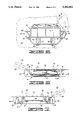
- FIG. 5 is an inner side elevational view of the spatula holder, showing its appearance from the inside of a grill hood upon which the spatula holder is mounted.
- the handle of the spatula is shown in dashed lines, as is the vertical wall of a smoke and fume hood to which the spatula holder is mounted.
- FIG. 6 is a top plan view of the spatula holder mounted upon the vertical wall of a hood, with the hood wall shown in dashed lines. A part of a spatula retained or held in the spatula holder i also illustrated in dashed lines.
- FIG. 7 is a bottom plan view of the spatula holder mounted on the wall of a hood.
- the hood is illustrated in dashed lines, and a spatula held in the spatula holder is also shown in lines.
- FIG. 8 is a side elevation view of the spatula holder of the invention when the spatula holder is unfolded to an inoperative, opened out position.
- FIG. 9 is a view of the opened out spatula holder, showing the opposite side thereof from that which is illustrated in FIG. 8.
- FIG. 10 is a sectional view taken along line 10--10 of FIG. 9.
- the spatula holder 8 of the invention may be best understood by initially referring to FIGS. 8 and 9. These figures show the spatula holder in its entirety, and show the two major parts of the spatula holder folded apart to their inoperative cleaning position.
- the two major parts of the spatula holder include a mounting part, designated generally by reference numeral 10, and being that part of the spatula holder which bears flatly against a vertical supporting surface upon which the spatula holder is mounted when it is in use.
- the mounting part 10 includes an inner, spatula-facing surface 12 and a wall or hood-facing surface 14 which is on the opposite side of the spatula-facing surface 12.
- the second major part of the spatula holder is a fold-up part denominated generally by reference numeral 16.
- the fold-up part 16 is connected to the mounting side 10 by a pair of flexible hinges 18 and 20 which interconnect the two parts in the manner illustrated in FIGS. 8 and 9. These hinges 18 and 20 permit the parts to be folded together in the manner illustrated in FIGS. 2 and 3.
- the fold-up part 16 of the spatula holder includes a protuberant boss 22 mounted on a spatula-facing surface 24.
- the fold-up part 16 has a ribbed surface 26 located on the opposite side of this part from the spatula-facing surface 24.
- the protuberant boss 22 projects into, and mates with, a recess or cavity 28 formed in the spatula-facing side 12 of the mounting part 10.
- the spatula-facing surface 24 of the fold-up side 16 defines and carries a spatula blade support ledge 30.
- the spatula blade support ledge 30 is best illustrated in FIG. 10 of the drawings which is a sectional view taken along line 10--10 of FIG. 9. Its function in supporting the blade of the spatula when the spatula is stored in the spatula holder will be hereinafter described.
- the ribbed surface On the reverse or opposite side of the fold-up part 16, the ribbed surface carries a series of protuberant interconnected ribs 31 which function to strengthen and reenforce the fold-up part of the spatula holder as hereinafter described.
- the fold-up part 16 At a side edge opposite the location of the hinges 18 and 20, the fold-up part 16 carries a beveled portion which includes a beveled surface 32.
- the beveled surface 32 tapers outwardly from the spatula-facing surface 24 away from the mounting part 10 as illustrated in FIGS. 2 and 9.
- This beveled surface 32 cooperates with a corresponding beveled or tapered surface 34 on the mounting part 10 to form a funnel-shaped mouth illustrated in FIGS. 2 and 3 of the drawings. This mouth functions to guide or direct the blade of a spatula into the spatula holder 8 when the holder is mounted in its operative position.
- the ribbed surface 26 On the reverse or opposite side of the fold-up part 16 the ribbed surface 26 carries a series of integrally formed, protuberant, interconnected reenforcing ribs 36 which function to strengthen and reenforce the fold-up part of the spatula holder.
- the wall or hood-facing surface 14 of the mounting part 10 carries a plurality of protuberant, interconnected ribs 38 which function to strengthen and reenforce the mounting part 10.
- the mounting part 10 defines a pair of mounting openings or holes 40 and 42.
- the shape or configuration of these holes can be perceived in FIGS. 8 and 9.
- Each of the mounting holes 40 and 42 has a round bolt or screw head-receiving portion, and a narrow neck portion which is oriented to extend upwardly from the bolt or screw head-receiving portion when the mounting part 10 is mounted on a wall or the panel of a hood.
- the fold-up part 16 defines a second pair of fastener openings or apertures 44 and 46.
- the fastener openings or apertures 44 and 46 are positioned in the fold-up part 16 to be in alignment with the openings 40 and 42 in the mounting part.
- the large bolt or screw head circular openings in the two sets of fastener apertures 40, 42, and 44, 46 will thus be aligned, as will the narrow neck portions which project upwardly therefrom when the spatula holder is mounted on a flat surface.
- This arrangement will permit the spatula holder to be quickly and easily disengaged from a wall, or from a side panel of a fume and smoke hood. This is accomplished by lifting the spatula holder upwardly so that the heads of bolts or screws used to engage the spatula holder to the wall or hood shift relatively downwardly to where such bolt or screw heads are aligned with the large circular opening portions of the fastener apertures 40, 42 and 44, 46. The spatula holder can then be removed by simply pulling it outwardly from the wall or hood until it is completely disengaged from, and free of, the bolt or screw fasteners which are used for mounting it.
- Pushing up the spatula holder to facilitate its disengagement from the fasteners can be easily accomplished by pushing upwardly on the downwardly facing beveled surfaces 50 and 52 carried on a pair of protuberant ear subassemblies denominated generally by reference numerals 54 and 56.
- these ears are characterized in having several other surfaces.
- the protuberant ear 54 includes a flat end surface 58 which corresponds to a similar flat end surface 60 formed on the protuberant ear 56.
- a flat, upwardly facing surface 62 is formed on the upper side of the protuberant ear 54, and a similar flat, upwardly facing surface 64 is formed on the upper side of the protuberant ear 56.
- a downwardly and inwardly inclined spatula-guiding and supporting surface 68 is formed on the front inner side of the protuberant ear 54.
- This inclined surface 68 functions to guide and support the portion of the blade which adjoins the handle of a spatula (as shown in dashed lines in FIG. 6).
- the protuberant ear 56 has a similar tapered surface 70 at the forward, inner side thereof and functions in the same way for supporting and guiding a part of the blade of a spatula.
- FIGS. 2 and 3 end elevation views of the folded-up operative spatula holder 8 are illustrated.
- the spatula holder 8 is here shown mounted to the inside surface of the vertically extending side panel 74 of a smoke or fume hood of the type used over a cooking grill.
- the spatula holder is mounted in this position by means of a pair of bolts each having a head (not visible), and a threaded shank.
- the shanks project through the hood panels 74 and are engaged by suitable nuts 76 as shown in FIGS. 2, 3, 6 and 7.
- the hood panel 74 and the nuts 76 are shown in dashed lines in the drawings.
- the vertically extending hood panel 74 as is fairly conventional in smoke hood construction, carries an outwardly turned end flange 78.
- the end flange 78 cooperates with the spatula holder 8 in limiting movement of a spatula mounted in the holder as the end flange 78 bears against a part of the spatula blade positioned at the illustrated location when the spatula is held in the spatula holder.
- FIGS. 5, 6 and 7 illustrate a part of a spatula 80 being held in the mounted spatula holder 8.
- the spatula includes a handle 82 Which may conventionally be constructed of wood, plastic, hard rubber or the like. Generally it will be preferably made of a material of low thermal conductivity.
- the spatula 80 further includes an elongated flat spatula blade 84.
- the spatula blade 84 is illustrated (FIG. 6) resting upon the spatula-supporting ledge 30 carried on the spatula-facing surface 24 of the fold-up part 16.
- the spatula blade 84 is connected to the handle 82 by an interconnecting metallic neck portion 86 which is formed integrally with the spatula blade 84.
- the entire spatula holder 8 of the invention is constructed of a unitary, integrally molded synthetic resin structure.
- the mounting part 10, the fold-up part 16 and the interconnecting hinges 18 and 20 are all integrally formed, as are the ribs carried on each of the two principal parts of the spatula holder.
- the headed screws or bolts which are to be used for mounting the spatula holder on a vertical surface may be first secured to the surface which is to support the holder.
- the nuts 76 may be initially used to engage the threaded shanks of bolts.
- the bolt heads carried at the other ends of the threaded shanks are spaced outwardly from the inwardly facing surface of the hood panel 74.
- the heads of these bolts (not visible) will be spaced inwardly from the inner surface of the hood panel 74 by a distance such that the bolt heads may be passed through the circular portions of the fastener openings or apertures 44 and 46 formed through the fold-up part 16 when the spatula holder 8 is mounted to the hood.
- the fold-up part 16 is folded up into juxtaposition to the mounting part 10 (in the fashion shown in FIGS. 2, 3, 5, 6 and 7), and while they are held in this juxtapositioned relationship, the bolt heads are extended through the circular portions of the aligned or registered aperture pairs 40, 42 and 44, 46, respectively.
- the two juxtapositioned parts 10 and 16 of the spatula holder 8 are then slid downwardly on the vertically extending mounting surface, such as the hood panel 74, until the heads of the fasteners are located in alignment with the narrow or reduced-width neck portions of the fastener openings or apertures 40-46.
- the spatula holder 8 With the spatula holder 8 mounted in its operative position in which the fold-up part 16 is folded into juxtaposition to the mounting part 10, the spatula holder is ready for use to receive a spatula 80 when the same is not in use for turning or moving food such as on a cooking grill located below the hood.
- the spatula blade denominated by reference numeral 84 is forced downwardly through the open mouth or guide channel formed by the opposed beveled surfaces 32 and 34 carried on the mounting part 10 and fold-up part 16, respectively. This opening and guide channel for the spatula blade is best shown in FIGS. 2 and 3 of the drawings.
- the blade 84 then continues to move downwardly until the edge of the blade comes to rest upon the blade-support surface or ledge 30 formed on the spatula-facing side 24 of the fold-up part 16.
- the neck of the blade denominated by reference numeral 86, is then supported on the beveled surface 68.
- the spatula is further retained in position by reason of the close proximity of the flange 78 carried on the hood panel 74 to the neck portion 86 of the blade 84.
- the spatula handle 82 projects outwardly away from the spatula holder 8 and away from the open, flanged end face of the hood so that it can be gripped with the hand without touching the hot hood.
- the cook simply grasps the handle 82 and lifts upwardly, and then commences to use the spatula in any ordinary fashion for cooking.
Landscapes
- Engineering & Computer Science (AREA)
- Food Science & Technology (AREA)
- Food-Manufacturing Devices (AREA)
Abstract
Description
Claims (14)
Priority Applications (1)
| Application Number | Priority Date | Filing Date | Title |
|---|---|---|---|
| US07/915,518 US5294082A (en) | 1992-07-20 | 1992-07-20 | Spatula holder |
Applications Claiming Priority (1)
| Application Number | Priority Date | Filing Date | Title |
|---|---|---|---|
| US07/915,518 US5294082A (en) | 1992-07-20 | 1992-07-20 | Spatula holder |
Publications (1)
| Publication Number | Publication Date |
|---|---|
| US5294082A true US5294082A (en) | 1994-03-15 |
Family
ID=25435886
Family Applications (1)
| Application Number | Title | Priority Date | Filing Date |
|---|---|---|---|
| US07/915,518 Expired - Lifetime US5294082A (en) | 1992-07-20 | 1992-07-20 | Spatula holder |
Country Status (1)
| Country | Link |
|---|---|
| US (1) | US5294082A (en) |
Cited By (1)
| Publication number | Priority date | Publication date | Assignee | Title |
|---|---|---|---|---|
| US20090222372A1 (en) * | 2006-11-17 | 2009-09-03 | Hiatt Jr John | Method of Creating and Trading Derivative Investment Products Based on a Statistical Property Reflecting the Volatility of an Underlying Asset |
Citations (3)
| Publication number | Priority date | Publication date | Assignee | Title |
|---|---|---|---|---|
| US4923153A (en) * | 1988-02-16 | 1990-05-08 | Kitagawa Industries Co., Ltd. | Strip clamp |
| US4930740A (en) * | 1988-06-27 | 1990-06-05 | Vogt Paul A | Eyewear holder |
| US5127616A (en) * | 1990-09-18 | 1992-07-07 | Carney Jack J | Pot lid and utensil holder |
-
1992
- 1992-07-20 US US07/915,518 patent/US5294082A/en not_active Expired - Lifetime
Patent Citations (3)
| Publication number | Priority date | Publication date | Assignee | Title |
|---|---|---|---|---|
| US4923153A (en) * | 1988-02-16 | 1990-05-08 | Kitagawa Industries Co., Ltd. | Strip clamp |
| US4930740A (en) * | 1988-06-27 | 1990-06-05 | Vogt Paul A | Eyewear holder |
| US5127616A (en) * | 1990-09-18 | 1992-07-07 | Carney Jack J | Pot lid and utensil holder |
Cited By (1)
| Publication number | Priority date | Publication date | Assignee | Title |
|---|---|---|---|---|
| US20090222372A1 (en) * | 2006-11-17 | 2009-09-03 | Hiatt Jr John | Method of Creating and Trading Derivative Investment Products Based on a Statistical Property Reflecting the Volatility of an Underlying Asset |
Similar Documents
| Publication | Publication Date | Title |
|---|---|---|
| US5848470A (en) | Impact actuated bakery grid device | |
| US4445250A (en) | Paint case | |
| US4109380A (en) | Cutting tool and blade holder for replaceable blades | |
| US5590475A (en) | Hand held appliance and holder assembly | |
| US20040016860A1 (en) | Cat litter scoop holder | |
| WO2019040777A1 (en) | Removable cookware handle | |
| US6746062B2 (en) | Collapsible grilling spatula | |
| US11350637B1 (en) | Detachable and easily cleanable meat tenderizer | |
| US4152831A (en) | Tool holder | |
| US8640906B2 (en) | Multipurpose cooking stove container | |
| US5294082A (en) | Spatula holder | |
| US5666874A (en) | Saucepan permitting placing of a stirring spoon in a stable manner thereon | |
| US1864039A (en) | Utensil holder | |
| US1057541A (en) | Rack for holding brushes. | |
| US2623230A (en) | Dry mop cleaning apparatus | |
| US4707087A (en) | Portable adjustable mirror assembly | |
| US11344034B1 (en) | Detachable and easily cleanable meat tenderizer | |
| JPH0445661Y2 (en) | ||
| US5564146A (en) | Multipurpose utensil | |
| CN218791733U (en) | Peeling knife | |
| CN223830897U (en) | Easily-disassembled door structure for oven | |
| TWM548506U (en) | Handle of cookware | |
| JPH0220967Y2 (en) | ||
| US2811734A (en) | Floor mop construction | |
| JP3027661U (en) | Knife, knife peeling adapter and holder |
Legal Events
| Date | Code | Title | Description |
|---|---|---|---|
| AS | Assignment |
Owner name: CONTINENTAL CARLISLE INC., OKLAHOMA Free format text: ASSIGNMENT OF ASSIGNORS INTEREST.;ASSIGNOR:FINNEY, LLOYD M.;REEL/FRAME:006218/0025 Effective date: 19920713 |
|
| STCF | Information on status: patent grant |
Free format text: PATENTED CASE |
|
| AS | Assignment |
Owner name: CARLISLE FOODSERVICE PRODUCTS, INCORPORATED, OKLAH Free format text: CHANGE OF NAME;ASSIGNOR:CONTINENTAL CARLISLE INCORPORATED;REEL/FRAME:008094/0777 Effective date: 19960228 |
|
| FPAY | Fee payment |
Year of fee payment: 4 |
|
| FEPP | Fee payment procedure |
Free format text: PAYOR NUMBER ASSIGNED (ORIGINAL EVENT CODE: ASPN); ENTITY STATUS OF PATENT OWNER: LARGE ENTITY |
|
| FPAY | Fee payment |
Year of fee payment: 8 |
|
| FPAY | Fee payment |
Year of fee payment: 12 |