US5293524A - Uniformly wound superconducting coil and method of making same - Google Patents
Uniformly wound superconducting coil and method of making same Download PDFInfo
- Publication number
- US5293524A US5293524A US07/964,760 US96476092A US5293524A US 5293524 A US5293524 A US 5293524A US 96476092 A US96476092 A US 96476092A US 5293524 A US5293524 A US 5293524A
- Authority
- US
- United States
- Prior art keywords
- mandrel
- coil
- wire
- ribbons
- superconducting
- Prior art date
- Legal status (The legal status is an assumption and is not a legal conclusion. Google has not performed a legal analysis and makes no representation as to the accuracy of the status listed.)
- Expired - Fee Related
Links
- 238000004519 manufacturing process Methods 0.000 title description 7
- 238000004804 winding Methods 0.000 claims abstract description 40
- 238000000034 method Methods 0.000 claims abstract description 22
- 239000010410 layer Substances 0.000 claims description 8
- 239000000853 adhesive Substances 0.000 claims description 6
- 230000001070 adhesive effect Effects 0.000 claims description 6
- 239000002356 single layer Substances 0.000 claims description 4
- 238000005452 bending Methods 0.000 claims 1
- 230000000750 progressive effect Effects 0.000 claims 1
- 125000006850 spacer group Chemical group 0.000 abstract description 15
- 239000002245 particle Substances 0.000 description 10
- 239000000463 material Substances 0.000 description 4
- 238000005481 NMR spectroscopy Methods 0.000 description 3
- 238000004513 sizing Methods 0.000 description 3
- 230000005469 synchrotron radiation Effects 0.000 description 3
- XEEYBQQBJWHFJM-UHFFFAOYSA-N Iron Chemical compound [Fe] XEEYBQQBJWHFJM-UHFFFAOYSA-N 0.000 description 2
- 238000003384 imaging method Methods 0.000 description 2
- 238000005339 levitation Methods 0.000 description 2
- 230000005405 multipole Effects 0.000 description 2
- 238000013421 nuclear magnetic resonance imaging Methods 0.000 description 2
- 229920003223 poly(pyromellitimide-1,4-diphenyl ether) Polymers 0.000 description 2
- 229920005989 resin Polymers 0.000 description 2
- 239000011347 resin Substances 0.000 description 2
- 239000002887 superconductor Substances 0.000 description 2
- 239000011248 coating agent Substances 0.000 description 1
- 238000000576 coating method Methods 0.000 description 1
- 239000004020 conductor Substances 0.000 description 1
- 238000010276 construction Methods 0.000 description 1
- 230000000694 effects Effects 0.000 description 1
- 230000005611 electricity Effects 0.000 description 1
- 230000004907 flux Effects 0.000 description 1
- 230000004927 fusion Effects 0.000 description 1
- 238000009413 insulation Methods 0.000 description 1
- 229910052742 iron Inorganic materials 0.000 description 1
- 230000005415 magnetization Effects 0.000 description 1
- 238000012986 modification Methods 0.000 description 1
- 230000004048 modification Effects 0.000 description 1
- 229920002379 silicone rubber Polymers 0.000 description 1
- 239000007787 solid Substances 0.000 description 1
Images


Classifications
-
- H—ELECTRICITY
- H01—ELECTRIC ELEMENTS
- H01F—MAGNETS; INDUCTANCES; TRANSFORMERS; SELECTION OF MATERIALS FOR THEIR MAGNETIC PROPERTIES
- H01F41/00—Apparatus or processes specially adapted for manufacturing or assembling magnets, inductances or transformers; Apparatus or processes specially adapted for manufacturing materials characterised by their magnetic properties
- H01F41/02—Apparatus or processes specially adapted for manufacturing or assembling magnets, inductances or transformers; Apparatus or processes specially adapted for manufacturing materials characterised by their magnetic properties for manufacturing cores, coils, or magnets
- H01F41/04—Apparatus or processes specially adapted for manufacturing or assembling magnets, inductances or transformers; Apparatus or processes specially adapted for manufacturing materials characterised by their magnetic properties for manufacturing cores, coils, or magnets for manufacturing coils
- H01F41/048—Superconductive coils
-
- Y—GENERAL TAGGING OF NEW TECHNOLOGICAL DEVELOPMENTS; GENERAL TAGGING OF CROSS-SECTIONAL TECHNOLOGIES SPANNING OVER SEVERAL SECTIONS OF THE IPC; TECHNICAL SUBJECTS COVERED BY FORMER USPC CROSS-REFERENCE ART COLLECTIONS [XRACs] AND DIGESTS
- Y10—TECHNICAL SUBJECTS COVERED BY FORMER USPC
- Y10T—TECHNICAL SUBJECTS COVERED BY FORMER US CLASSIFICATION
- Y10T29/00—Metal working
- Y10T29/49—Method of mechanical manufacture
- Y10T29/49002—Electrical device making
- Y10T29/49014—Superconductor
Definitions
- the present invention relates to a method of winding a coil of superconducting wire for a superconducting magnet, and, more particularly, to a winding arrangement wherein the windings of the coil are uniform and dense, such that the resulting superconducting magnet produces a strong and homogeneous magnetic field and yet is physically compact and energy efficient.
- Superconducting magnets and the methods of their manufacture are well known in the art. At cryogenic temperatures, superconducting wire loses virtually all ohmic resistance and allows the free flow of electricity for long periods of time and in very high current densities. Because the current density in a superconducting coil can be hundreds of times higher than in nonsuperconducting coils, very strong magnetic fields can be obtained, and, as a result, superconducting magnets have found extensive application in devices such as high energy particle accelerators, plasma confining tokamaks, synchrotron radiation sources, nuclear magnetic resonance imaging systems, and magnetic levitation devices. However, due to continuous demands for greater power and accuracy of these devices, there is a continual need for a more efficient superconducting magnet which can provide stronger and more homogeneous magnetic fields and at the same time is physically more compact and requires less power.
- a prime example of the application of more efficient superconducting magnets is in the construction of the Superconducting Super Collider (SSC) particle accelerator which will use thousands of superconducting magnets to bend and focus high energy particle beams in a generally circular orbit.
- SSC Superconducting Super Collider
- the main superconducting magnetic coils of the SSC are designed to exhibit minimal magnetic field harmonics, due to superconductor magnetization effects, iron saturation and coil positioning errors, certain harmonic errors are possible which must be corrected with multipole corrector or adjustment coils.
- multipole corrector coils are utilized to focus the particle beam into a desired stream, so as the energy of the particles increases, the strength of the corrector coils must likewise be increased. Therefore, there is a need for corrector coils which can provide strong and homogeneous magnetic field and, yet, are compact and energy efficient.
- corrector coils to correct magnetic field deviations and to focus the particle beam
- the production and use of these coils are complicated by a number of factors.
- the superconducting wires utilized in the windings are typically of very small diameter and are generally more brittle than normal conductors, so therefore greater care must be exercised in the winding and forming of such superconducting magnets.
- Another factor is that the coils are very lengthy (more than a meter in length) while the spacing between the adjacent turns of the coil must be precisely maintained, so it is difficult and time consuming to wind uniform layers of wire which are physically stable so as to prevent generation of frictional heat from coil movement resulting from the electromotive forces of the large currents. Additionally, the coils must be physically compact so that it may easily be cooled to cryogenic temperatures.
- one of the requirements for an efficient superconducting magnet is that it have a uniform, homogeneous cross-section with a high density of superconducting wire within its cross-sectional area. As the windings are made more uniform and with greater cross-sectional density, the magnetic field produced by the windings is stronger and more homogeneous. This also means that the resulting superconducting magnet requires less energy and, yet, is physically more compact. These advantages would also facilitate greater flexibility in the positioning of these corrector coils about the bore tube and make it easier to cryogenically cool the same.
- NMR nuclear magnetic resonance
- the general object of this invention is to provide a method of winding a coil of superconducting wire for a superconducting magnet having a relatively dense and uniformly spaced windings to enhance the homogeneity and strength of the magnetic field produced by the superconducting magnet.
- Another object of this invention to provide a mandrel for winding a coil of superconducting wire for a superconducting magnet having a relatively dense and uniformly spaced windings.
- Yet another object of this invention is to provide a coil of superconducting wire having relatively dense and uniformly spaced windings.
- this invention provides a method and apparatus for winding a coil of superconducting wire to form a superconducting magnet having a relatively dense and uniformly spaced winding to enhance homogeneity and strength of the magnetic field surrounding the coil.
- the method includes winding the superconducting wire about a mandrel having a plurality of outwardly opening, laterally parallel slots extending about the periphery of the mandrel which are sized to receive and outwardly align and retain successive turns of the superconducting wire in each slot as the wire is wound around and laterally across the mandrel to form and retain the coil about the mandrel.
- the turns of the superconducting wire are bonded together to form an integral ribbon of wire within each of the slots, whereafter the mandrel is disassembled to facilitate removing the coil from the mandrel while retaining its wire ribbon configuration. Thereafter, the coil is bent to align the coil ribbons in a pre-established configuration and subsequently bonded to secure the ribbons to form the coil.
- the mandrel about which the superconducting wire is wound comprises removable spacers and retainers which cooperate to form the outwardly opening slots noted above.
- This arrangement has been found to be particularly suited for coil fabrication as it is readily adaptable for sizing the slots to facilitate winding the superconducting wire around and laterally across the mandrel to form the wire ribbons while at the same time maintaining a predetermined thickness for each of the ribbons and providing an arrangement from which the coil can be readily disengaged without damage.
- the resulting coil of superconducting wire comprises windings formed into a plurality of wire ribbons along the lateral width of the coil.
- Each of the wire ribbons includes a predetermined number of wire turns which are bonded together to form the ribbons.
- These ribbons are in turn aligned and bonded in an essentially side-by-side parallel fashion along the thickness of the coil to form a coil having a predetermined cross-sectional profile, shaped and bonded into a predetermined configuration to obtain desired magnetic field densities.
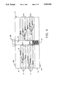
- FIG. 1 is a partial pictorial view of the mandrel of the present invention after it has been assembled
- FIG. 2 is a exploded partial pictorial view of the mandrel shown in FIG. 1;
- FIG. 3 is a cross-sectional view of the mandrel taken substantially along line 3--3 in FIG. 1 showing the superconducting wire as it is wound on the mandrel;
- FIG. 4 is a cross-sectional view of the mandrel taken substantially along line 4--4 in FIG. 1 showing the ribbon-like configuration of the windings of the superconducting wire as it is wound on the mandrel;
- FIG. 5 is a partial plan view of a superconducting coil fabricated according to the invention.
- FIG. 6 is a lateral side view of the coil shown in FIG. 5;
- FIG. 7 is an end view of the coil in FIG. 6.
- FIG. 8 is an enlarged cross-sectional view of the coil taken substantially along line 8--8 in FIG. 6.
- the invention calls for using a mandrel assembly 10 to wind a uniform and dense coil 1 of superconducting wire 11 for a superconducting magnet.
- the mandrel 10 includes a plurality of spacer plates 12 and mandrel or spool plates 13 sandwiched between one another in alternating layers and secured together between two base or supporting end plates 14 and 15.
- a plurality of equally spaced and cooperatively aligned holes 16 sized to receive dowels 17 are provided in the spacer plates 12, mandrel plates 13, and base or end plates 14 and 15 for aligning the plates.
- a pair of bolts 18 are inserted through the remaining holes 16 and threaded into the correspondingly aligned holes 19 tapped into the base plate 14 to secure the mandrel assembly together as shown in FIG. 1.
- Assembly of the mandrel 10 is performed by laying out the first base plate 14 and placing dowel pins 17 into the corresponding holes 16 in the first base plate 14.
- a spacer plate 12 is placed adjacent to the first base plate 14, being guided and aligned by dowel pins 17 inserted into the holes of the first base plate 14.
- one of the mandrel plates 13 is placed adjacent to the spacer plate 12, being also guided and aligned by the same dowel pins 16.
- the foregoing sequence of placing alternating layers of spacer and mandrel plates is continued until the desired thickness of the mandrel is achieved, which, of course, depends on the lateral thickness of the coil to be formed.
- a second base or end plate 15 is placed adjacent to the final tier of the mandrel plate 13 and the mandrel assembly is secured together with the bolts 18 as noted above.
- any one of a variety of releasable fasteners can be used for this purpose in lieu of bolts or the like.
- FIGS. 3 and 4 illustrate one embodiment of the mandrel 10 showing several turns of a superconducting wire 11 wound about the mandrel.
- the size of the base plates 14 and 15 and the spacer plates 12 is substantially the same.
- mandrel plates 13 are smaller, so that, when placed in alternating layers with the spacer plates, the mandrel plates form a spool 20 tapered along its sides in an essentially trapezoidal cross-sectional configuration which defines the inner periphery of a plurality of outwardly opening parallel slots 21, extending generally about the periphery of the mandrel.
- Each of the slots 21 is sized to receive, retain and outwardly align successive turns of the superconducting wire 11 in an essentially ribbon-like configuration during fabrication of the coil 1.
- the spacer plates 12 are each provided with notches 22 for passing the turns of the superconducting wire 11 between adjacent slots 21 as the coil is wound, and the corners 23 of the mandrel plates 13 are rounded to minimize interference with the wire as it is wound on the mandrel assembly.
- FIGS. 3 and 4 best illustrate the relative thicknesses of the various plates used to assemble the mandrel 10.
- the thickness of the mandrel plates 13 is slightly greater than the thickness of the wire 11 to allow the turns of the coil to be wound into single layer wire ribbons 24 within the slots 21, although it should be noted that in some embodiments it may be appropriate to form the wire ribbons in layers of two or more wires depending on the material characteristics of the wire. In either event, the thickness of the spacer plates 12 is such that they properly separate and support the wire turns as each ribbon is formed.
- the thickness of the base plates 14 and 15 is such that they properly support and provide rigidity to the mandrel assembly 10 as the wire 11 is first wound and later bonded together.
- mandrel 10 including spacer plates 12, mandrel plates 13 and base plates 14 and 15 are preferably constructed of the same or similar materials having substantially the same heat expansion characteristics as that of the wire 11 used to wind the coils. As will be appreciated, this facilitates the use of heat bonding or fusing techniques during fabrication of the coil without damaging the superconducting wire due to differing heat expansion characteristics of the materials.
- the superconducting wire 11 used to wind the coil 1 is preferably formed of a small diameter superconductor wrapped in a thin layer of insulating resin such as Kapton insulation (Kapton is a trademark of Westinghouse Electric Corporation) which is then overlaid with a thin layer of heat activated high temperature plastic adhesive such as those sold under the Bondall or XMPI trademarks (Bondall and XMPI are trademarks of E.I. DuPont de Nemours & Co.).
- the adhesive provides a means for bonding the turns of the superconducting wire 11 into a solid and rigid coil of wire, thereby obviating the necessity for the difficult and laborious process of impregnating the coil with resin or silicon rubber to attain structural stability as has typically been used in the past.
- the superconducting wire used for the coil in this case may be any one of a variety of commercially available wire types such as 2.2 ratio wire manufactured by Outokompu or Barcel Cable and Wire Companies.
- the lead end of the superconducting wire 11 is attached to the first base plate 14 of the mandrel 10 by means of a bobbin 25 or other such conventional device affixed to the outer edge of the mandrel 14. Thereafter, the wire 11 is wound around the mandrel 10 within the slots 21 defined by the alternating spacer and mandrel plates 12 and 13. While winding, sufficient tension is maintained in the wire 11 to attain smooth and dense windings within each slot 21. After each revolution or turn of the wire 11 about the mandrel 10 within each slot 21, the wire is guided through the outwardly opening notch 22 in the end of the respective spacer plate 12 to reach the next adjacent slot 21.
- the entire assembly is placed into an oven at an appropriate temperature for a period of time sufficient to activate the heat activated adhesive coating on the superconducting wire to bond the windings of the superconducting wire 11 together in ribbons 24.
- the coil was heated to about 250° F. for four hours.
- removable shims (not shown) having substantially the same thickness as the wire 11 may be inserted into the slots 21 on the four sides of the mandrel to provide additional restraints to hold the windings in each slot in position while they are being heated to bond them together.
- the shims should be made of a material whose thermal expansion characteristics are substantially the same as that of the wire 11.
- the mandrel 10 is disengaged from the partially completed coil 1 without disturbing the coil's ribbon-like configuration. Removal of the mandrel components is accomplished by first removing the bolts 18 and removing the second base plate 15. Next, the pins 17 are slid out of the assembly. Thereafter, the spacer plates 12 are carefully separated from the coil windings and withdrawn from the assembly at the end opposite from the notches 22. Then, mandrel plates 13 are removed, beginning with the largest plate, until all of the mandrel plates 13 have been removed.
- the coil After disengagement of the partially completed coil 1 from the mandrel 10, the coil is shaped into an elongated, U-shaped configuration to obtain the desired magnetic field densities as shown in FIGS. 5-8.
- a suitable jig or holder (not shown) is used to shape and retain the coil during this step of the fabrication process.
- the particular configuration selected depends on the desired magnetic field characteristics.
- the coil is again placed into an oven at an appropriate temperature for a period of time sufficient to fuse the heat sensitive plastic adhesive to bond the windings of the superconducting wire together in the desired configuration. In this case, the coil was again heated to about 250° F. for four hours.
- the coil 1 comprises windings formed into a plurality of wire ribbons 24 across the thickness of the coil, wherein each of the ribbons includes a predetermined number of wire turns which are laterally aligned and bonded together in an essentially side-by-side parallel fashion to the other ribbons across the thickness of the coil.
- the ribbons 24 have been positioned to form relatively flat ends 27 on the side legs 28 of the coil when it is bent into its final configuration. This has been accomplished by appropriately sizing the lateral width of the mandrel plates 13 to form the tapered spool indicated at 20, although it is to be understood that other desired end profiles (i.e. curves, slopes or the like) can be obtained by selectively sizing the lateral width of the mandrel plates.
- the resulting coil 1 of superconducting wire 11 comprises an essentially uniform and dense winding of wire which enhances the homogeneity and strength of the magnetic field produced by the coil. Likewise, the efficiency of the coil is improved, allowing for the operation of the superconducting magnet at reduced currents and in a physically more compact form.
- the invention is particularly suited for producing superconducting magnets used in high energy particle accelerators, plasma confining devices for nuclear fusion, synchrotron radiation sources, nuclear magnetic resonance imaging systems, magnetic leviation devices and related uses where precision and control of magnetic fields is particularly critical.
- the embodiment disclosed is particularly suited for use as a corrector coil in a particle accelerator to correct and adjust the magnetic field of the main superconducting coils and focus high energy particle beams into a stream of particles suitable for experimentation.
Landscapes
- Engineering & Computer Science (AREA)
- Power Engineering (AREA)
- Manufacturing & Machinery (AREA)
- Particle Accelerators (AREA)
Abstract
Description
Claims (17)
Priority Applications (1)
| Application Number | Priority Date | Filing Date | Title |
|---|---|---|---|
| US07/964,760 US5293524A (en) | 1992-10-15 | 1992-10-15 | Uniformly wound superconducting coil and method of making same |
Applications Claiming Priority (1)
| Application Number | Priority Date | Filing Date | Title |
|---|---|---|---|
| US07/964,760 US5293524A (en) | 1992-10-15 | 1992-10-15 | Uniformly wound superconducting coil and method of making same |
Publications (1)
| Publication Number | Publication Date |
|---|---|
| US5293524A true US5293524A (en) | 1994-03-08 |
Family
ID=25508947
Family Applications (1)
| Application Number | Title | Priority Date | Filing Date |
|---|---|---|---|
| US07/964,760 Expired - Fee Related US5293524A (en) | 1992-10-15 | 1992-10-15 | Uniformly wound superconducting coil and method of making same |
Country Status (1)
| Country | Link |
|---|---|
| US (1) | US5293524A (en) |
Cited By (11)
| Publication number | Priority date | Publication date | Assignee | Title |
|---|---|---|---|---|
| US5551144A (en) * | 1994-12-29 | 1996-09-03 | General Electric Company | Method of making insulated superconducting magnet coil |
| US20020130749A1 (en) * | 2001-03-14 | 2002-09-19 | Hay Noah David | Combs for disk wound transformers |
| US6601289B1 (en) * | 1999-05-10 | 2003-08-05 | Sumitomo Electric Industries, Ltd. | Manufacturing process of superconducting wire and retainer for heat treatment |
| US6922885B2 (en) * | 2001-05-15 | 2005-08-02 | General Electric Company | High temperature superconducting racetrack coil |
| US20060055494A1 (en) * | 2004-09-11 | 2006-03-16 | Bruker Biospin Gmbh | Superconductor magnet coil configuration |
| DE102004043988B3 (en) * | 2004-09-11 | 2006-05-11 | Bruker Biospin Gmbh | Superconductive magnet coil arrangement |
| US20070152786A1 (en) * | 2005-12-30 | 2007-07-05 | Choi Kyeong D | Method of manufacturing continuous disk winding for high-voltage superconducting transformers |
| US20070188280A1 (en) * | 2006-02-13 | 2007-08-16 | Heui-Joo Park | Superconductive coil assembly having improved cooling efficiency |
| US20110152104A1 (en) * | 2009-12-18 | 2011-06-23 | International Business Machines Corporation | Superconducting Low Pass Filter for Quantum Computing and Method of Manufacturing the Same |
| US20120286084A1 (en) * | 2011-05-13 | 2012-11-15 | Tae-Kuk Ko | Bobbin for layer winding of superconducting wire and layer winding method using the same |
| JP2016529687A (en) * | 2013-04-26 | 2016-09-23 | メドトロニック・ナビゲーション,インコーポレーテッド | Electromagnetic coil placement and manufacturing method for surgical navigation |
Citations (4)
| Publication number | Priority date | Publication date | Assignee | Title |
|---|---|---|---|---|
| US4255849A (en) * | 1977-11-28 | 1981-03-17 | Siemens Aktiengesellschaft | Method for constructing a superconducting magnet winding |
| US4561175A (en) * | 1982-11-30 | 1985-12-31 | Mitsubishi Denki Kabushiki Kaisha | Method of winding a superconducting coil |
| US4679020A (en) * | 1985-05-31 | 1987-07-07 | Mitsubishi Denki Kabushiki Kaisha | Superconducting solenoid and method of making same |
| USH383H (en) * | 1987-05-15 | 1987-12-01 | The United States Of America As Represented By The United States Department Of Energy | Laminated magnet field coil sheath |
-
1992
- 1992-10-15 US US07/964,760 patent/US5293524A/en not_active Expired - Fee Related
Patent Citations (4)
| Publication number | Priority date | Publication date | Assignee | Title |
|---|---|---|---|---|
| US4255849A (en) * | 1977-11-28 | 1981-03-17 | Siemens Aktiengesellschaft | Method for constructing a superconducting magnet winding |
| US4561175A (en) * | 1982-11-30 | 1985-12-31 | Mitsubishi Denki Kabushiki Kaisha | Method of winding a superconducting coil |
| US4679020A (en) * | 1985-05-31 | 1987-07-07 | Mitsubishi Denki Kabushiki Kaisha | Superconducting solenoid and method of making same |
| USH383H (en) * | 1987-05-15 | 1987-12-01 | The United States Of America As Represented By The United States Department Of Energy | Laminated magnet field coil sheath |
Cited By (18)
| Publication number | Priority date | Publication date | Assignee | Title |
|---|---|---|---|---|
| US5551144A (en) * | 1994-12-29 | 1996-09-03 | General Electric Company | Method of making insulated superconducting magnet coil |
| US6601289B1 (en) * | 1999-05-10 | 2003-08-05 | Sumitomo Electric Industries, Ltd. | Manufacturing process of superconducting wire and retainer for heat treatment |
| US20020130749A1 (en) * | 2001-03-14 | 2002-09-19 | Hay Noah David | Combs for disk wound transformers |
| US6709615B2 (en) * | 2001-03-14 | 2004-03-23 | Square D Company | Method of manufacturing a comb for winding coils of a disk wound transformer |
| US6922885B2 (en) * | 2001-05-15 | 2005-08-02 | General Electric Company | High temperature superconducting racetrack coil |
| US20070008055A1 (en) * | 2004-09-11 | 2007-01-11 | Bruker Biospin Gmbh | Superconductor magnet coil configuration |
| DE102004043988B3 (en) * | 2004-09-11 | 2006-05-11 | Bruker Biospin Gmbh | Superconductive magnet coil arrangement |
| DE102004043987B3 (en) * | 2004-09-11 | 2006-05-11 | Bruker Biospin Gmbh | Superconductive magnet coil arrangement |
| US20060055494A1 (en) * | 2004-09-11 | 2006-03-16 | Bruker Biospin Gmbh | Superconductor magnet coil configuration |
| US7317369B2 (en) | 2004-09-11 | 2008-01-08 | Bruker Biospin Gmbh | Superconductor magnet coil configuration |
| US7330092B2 (en) | 2004-09-11 | 2008-02-12 | Bruker Biospin Gmbh | Superconductor magnet coil configuration |
| US20070152786A1 (en) * | 2005-12-30 | 2007-07-05 | Choi Kyeong D | Method of manufacturing continuous disk winding for high-voltage superconducting transformers |
| US7383625B2 (en) * | 2005-12-30 | 2008-06-10 | Korea Polytechnic University | Method of manufacturing continuous disk winding for high-voltage superconducting transformers |
| US20070188280A1 (en) * | 2006-02-13 | 2007-08-16 | Heui-Joo Park | Superconductive coil assembly having improved cooling efficiency |
| US20110152104A1 (en) * | 2009-12-18 | 2011-06-23 | International Business Machines Corporation | Superconducting Low Pass Filter for Quantum Computing and Method of Manufacturing the Same |
| US8745850B2 (en) * | 2009-12-18 | 2014-06-10 | International Business Machines Corporation | Method of manufacturing superconducting low pass filter for quantum computing |
| US20120286084A1 (en) * | 2011-05-13 | 2012-11-15 | Tae-Kuk Ko | Bobbin for layer winding of superconducting wire and layer winding method using the same |
| JP2016529687A (en) * | 2013-04-26 | 2016-09-23 | メドトロニック・ナビゲーション,インコーポレーテッド | Electromagnetic coil placement and manufacturing method for surgical navigation |
Similar Documents
| Publication | Publication Date | Title |
|---|---|---|
| Song et al. | 2G HTS coil technology development at SuperPower | |
| EP0167129B1 (en) | Winding support and method for nmr magnet axisymmetric correction coils | |
| US4554731A (en) | Method and apparatus for making superconductive magnet coils | |
| US5293524A (en) | Uniformly wound superconducting coil and method of making same | |
| Kirby et al. | Hi-Lumi LHC twin aperture orbit correctors 0.5-m model magnet development and cold test | |
| JPS6124209A (en) | Correcting coil assembly | |
| Lorin et al. | Design of a Nb 3 Sn 16 T block dipole for the future circular collider | |
| US4135294A (en) | Winding a multi-pancake magnet from a continuous conductor | |
| Liang et al. | Design and test of a half-aperture canted-cosine-theta multipole prototype magnet for the HIAF FRagment separator | |
| US9793036B2 (en) | Low temperature superconductor and aligned high temperature superconductor magnetic dipole system and method for producing high magnetic fields | |
| Zangenberg et al. | Conduction cooled high temperature superconducting dipole magnet for accelerator applications | |
| Khodzhibagiyan et al. | Superconducting magnets for the NICA accelerator collider project | |
| Bleser et al. | Superconducting magnets for the CBA project | |
| Novitski et al. | Design and assembly of a large-aperture Nb 3 Sn cos-theta dipole coil with stress management in dipole mirror configuration | |
| USH383H (en) | Laminated magnet field coil sheath | |
| Khodzhibagiyan et al. | Production and test status of the superconducting magnets for the NICA project and the SIS100 synchrotron | |
| Jo et al. | High temperature superconducting synchronous motor | |
| Anerella et al. | Construction and testing of curved ReBCO coils | |
| US10062486B1 (en) | High performance superconducting undulator | |
| Dahl et al. | Construction of cold mass assembly for full-length dipoles for the SSC accelerator | |
| Kahn et al. | A dipole magnet for the FRIB high radiation environment nuclear fragment separator | |
| Fuerst et al. | Review of new developments in superconducting undulator technology at the APS | |
| Peoples | Status of the SSC superconducting magnet program | |
| Wyss | The LHC magnet programme: from accelerator physics requirements to production in industry | |
| JP3146426B2 (en) | Superconducting coil, method of manufacturing the same, and coil bobbin used for superconducting coil |
Legal Events
| Date | Code | Title | Description |
|---|---|---|---|
| AS | Assignment |
Owner name: ENERGY, DEPARTMENT OF, UNITED STATES OF AMERICA, T Free format text: ASSIGNMENT OF ASSIGNORS INTEREST;ASSIGNORS:MOOKERJEE, SUMIT;YAGER, BILLY;SHEN, WEIJUN;REEL/FRAME:006712/0204;SIGNING DATES FROM 19930730 TO 19930810 |
|
| FEPP | Fee payment procedure |
Free format text: PAT HOLDER CLAIMS SMALL ENTITY STATUS - SMALL BUSINESS (ORIGINAL EVENT CODE: SM02); ENTITY STATUS OF PATENT OWNER: SMALL ENTITY |
|
| FEPP | Fee payment procedure |
Free format text: PAYOR NUMBER ASSIGNED (ORIGINAL EVENT CODE: ASPN); ENTITY STATUS OF PATENT OWNER: SMALL ENTITY |
|
| FPAY | Fee payment |
Year of fee payment: 4 |
|
| AS | Assignment |
Owner name: UNIVERSITIES RESEARCH ASSOCIATION, INC., DISTRICT Free format text: ASSIGNMENT OF ASSIGNORS INTEREST;ASSIGNOR:ENERGY, U.S. DEPARTMENT OF, AS REPRESENTED BY,;REEL/FRAME:008698/0942 Effective date: 19970908 |
|
| AS | Assignment |
Owner name: ENERGY, UNITED STATES DEPARTMENT OF, DISTRICT OF C Free format text: CONFIRMATORY LICENSE;ASSIGNOR:UNIVERSITIES RESEARCH ASSOCIATION, INC.;REEL/FRAME:008920/0684 Effective date: 19970212 |
|
| FPAY | Fee payment |
Year of fee payment: 8 |
|
| REMI | Maintenance fee reminder mailed | ||
| LAPS | Lapse for failure to pay maintenance fees | ||
| STCH | Information on status: patent discontinuation |
Free format text: PATENT EXPIRED DUE TO NONPAYMENT OF MAINTENANCE FEES UNDER 37 CFR 1.362 |
|
| FP | Lapsed due to failure to pay maintenance fee |
Effective date: 20060308 |
|
| AS | Assignment |
Owner name: FERMI RESEARCH ALLIANCE, LLC, ILLINOIS Free format text: ASSIGNMENT OF ASSIGNORS INTEREST;ASSIGNOR:UNIVERSITIES RESEARCH ASSOCIATION, INC.;REEL/FRAME:018535/0363 Effective date: 20061120 |