US5291768A - Plastic key tag with a key bar - Google Patents
Plastic key tag with a key bar Download PDFInfo
- Publication number
- US5291768A US5291768A US07/867,830 US86783092A US5291768A US 5291768 A US5291768 A US 5291768A US 86783092 A US86783092 A US 86783092A US 5291768 A US5291768 A US 5291768A
- Authority
- US
- United States
- Prior art keywords
- plates
- tongue
- plate
- key
- key tag
- Prior art date
- Legal status (The legal status is an assumption and is not a legal conclusion. Google has not performed a legal analysis and makes no representation as to the accuracy of the status listed.)
- Expired - Lifetime
Links
Images

Classifications
-
- A—HUMAN NECESSITIES
- A47—FURNITURE; DOMESTIC ARTICLES OR APPLIANCES; COFFEE MILLS; SPICE MILLS; SUCTION CLEANERS IN GENERAL
- A47G—HOUSEHOLD OR TABLE EQUIPMENT
- A47G29/00—Supports, holders, or containers for household use, not provided for in groups A47G1/00-A47G27/00 or A47G33/00
- A47G29/10—Key holders; Key boards
-
- A—HUMAN NECESSITIES
- A44—HABERDASHERY; JEWELLERY
- A44B—BUTTONS, PINS, BUCKLES, SLIDE FASTENERS, OR THE LIKE
- A44B15/00—Key-rings
-
- Y—GENERAL TAGGING OF NEW TECHNOLOGICAL DEVELOPMENTS; GENERAL TAGGING OF CROSS-SECTIONAL TECHNOLOGIES SPANNING OVER SEVERAL SECTIONS OF THE IPC; TECHNICAL SUBJECTS COVERED BY FORMER USPC CROSS-REFERENCE ART COLLECTIONS [XRACs] AND DIGESTS
- Y10—TECHNICAL SUBJECTS COVERED BY FORMER USPC
- Y10T—TECHNICAL SUBJECTS COVERED BY FORMER US CLASSIFICATION
- Y10T70/00—Locks
- Y10T70/80—Parts, attachments, accessories and adjuncts
- Y10T70/8432—For key-operated mechanism
- Y10T70/8676—Key holders
- Y10T70/8703—Flexible
-
- Y—GENERAL TAGGING OF NEW TECHNOLOGICAL DEVELOPMENTS; GENERAL TAGGING OF CROSS-SECTIONAL TECHNOLOGIES SPANNING OVER SEVERAL SECTIONS OF THE IPC; TECHNICAL SUBJECTS COVERED BY FORMER USPC CROSS-REFERENCE ART COLLECTIONS [XRACs] AND DIGESTS
- Y10—TECHNICAL SUBJECTS COVERED BY FORMER USPC
- Y10T—TECHNICAL SUBJECTS COVERED BY FORMER US CLASSIFICATION
- Y10T70/00—Locks
- Y10T70/80—Parts, attachments, accessories and adjuncts
- Y10T70/8432—For key-operated mechanism
- Y10T70/8676—Key holders
- Y10T70/873—One-piece
-
- Y—GENERAL TAGGING OF NEW TECHNOLOGICAL DEVELOPMENTS; GENERAL TAGGING OF CROSS-SECTIONAL TECHNOLOGIES SPANNING OVER SEVERAL SECTIONS OF THE IPC; TECHNICAL SUBJECTS COVERED BY FORMER USPC CROSS-REFERENCE ART COLLECTIONS [XRACs] AND DIGESTS
- Y10—TECHNICAL SUBJECTS COVERED BY FORMER USPC
- Y10T—TECHNICAL SUBJECTS COVERED BY FORMER US CLASSIFICATION
- Y10T70/00—Locks
- Y10T70/80—Parts, attachments, accessories and adjuncts
- Y10T70/8432—For key-operated mechanism
- Y10T70/8811—Key identification
Definitions
- This invention relates to a plastic key tag having a marker plate receptacle with a through hole used for hanging it and with an open tongue for fastening a key on the receptacle.
- This invention also relates to a plastic key bar with a plurality of hooks for receiving the key tag of this invention.
- the marker plate receptacle consists of two plates welded together, the plate oriented towards the visible side having a window.
- a through hole used for hanging the key tag is provided in the hanging position of use.
- a second through hole is positioned below the window, which also extends through both plates and through which is positioned an S-shaped metal tongue, in the manner of a hook.
- a slit positioned at the lower end is used for inserting the marker plate.
- Key tags have also been developed which are designed only for key bars which are particularly adapted to them.
- U.S. Pat. Nos. 4,072,033 and 4,137,740 disclose key tags which do not have through holes for hanging them from hooks.
- one side of the marker plate receptacles is equipped with a Velcro band, which is directly connected with a key bar also having a Velcro band.
- the key-receiving tongues are designed as metal rings.
- European Patent EP-PS-0,149,102 where a very complicated and expensive key bar is used, into which a key tag can be inserted from below.
- Such key tag has a marker plate receptacle with a pushbutton-like spring, which can be locked in an opening in the key bar.
- Such key tag has an annular element on its lower end on which a key can be fastened with a key ring. The embodiment of the tongue and how it is connected with the key tag cannot be determined from such document.
- the first object is accomplished with a key tag having a marker plate receptacle with a through hole for hanging it, wherein the key can be fastened on the receptacle.
- the marker plate receptacle has two plates connected in one piece with a film hinge and together, the plates form a foldable, form-fittingly lockable frame for receiving the marker plate.
- the second object is accomplished with a plastic key bar having a plurality of hooks for receiving the key tag of this invention, and having a groove over its entire length for inserting a marker strip, the width of which corresponds approximately to the height of the marker plates fitting into the marker plate receptacle.
- the distance between the groove and the hooks corresponds to the distance between the window and the hole of the key tag.
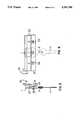
- FIG. 1 shows a key tag in the completely open position after manufacturing
- FIG. 2 shows a key tag still in the open position with the key already fixed on it
- FIG. 3 shows a key tag in the completed, assembled position ready for use
- FIG. 4 shows a section along the line A-A through the key tag as shown in FIG. 3;
- FIG. 5 shows a side view of a key bar, also in accordance with this invention, which is adapted to the key tag of this invention.
- FIG. 6 shows a front view of the key bar shown in FIG. 5.
- the key tag in accordance with this invention has a marker plate receptacle 1 comprising two plates 6 and 7 connected with each other via a film hinge 9.
- the two plates 6 and 7 are embodied in such a way that they form a rectangular portion 10 and a triangular portion 11, positioned on one longitudinal edge.
- the film hinge 9 connecting the two plates 6 and 7 extends along the second, common longitudinal edge of the respective rectangular portion 10.
- the inner surfaces of the two plates 6 and 7 are visible in FIGS. 1 and 2.
- the plate 6, shown on top in FIGS. 1 and 2 has the through hole 2 as its only perforation, which is used for hanging the key tag on a keyboard or a key bar. But the plate 7, shown relatively lower in FIGS. 1 and 2, has three openings.
- the window 8 visible on the top in FIG. 2, which allows a view of the marker plate 5 which is insertable and which is exchangeable.
- This window 8 is almost approximately of the same size as the rectangular portion 10 of the plate 7.
- a round through hole 3' is located exactly perpendicularly underneath the through hole 2 in the vicinity of the tip of the triangular portion 11.
- An open tongue 3 has been extruded in the extension of the tip of the triangular portion 11 of the lower plate 7, which has a hook 12 at its lower end. Perpendicularly to its extension, the tongue 3 has two film hinges 12' located relatively close to each other.
- the marker plate 5, provided with an identification is placed through the window 8 in the plate 7 into the folded-open marker plate receptacle 1. Then the key 4 to be hung up is threaded on the open tongue 3. The lower end of the tongue 3 with its hook 12 is then rotated upwards by 180°. Next, the key 4 comes to rest exactly between the two film hinges 12' of the tongue 3.
- the through hole 2 in the lower plate 7 is provided with an annular wall 16, upwardly extending perpendicular to the plane of the plate, which is provided on its top with a form closure ridge 17, as shown in FIG. 4.
- the hook 12 of the tongue 3 fits in an exactly form-fitting manner around this vertical annular wall 16.
- the form closure ridge 17 causes the hook 12 of the tongue 3 to remain in its position, when the lower part is pivoted by 180°, as shown in FIG. 2. Now the upper plate 6 is pivoted by 180° around the film hinge 9 onto the lower plate 7, so that the inner surfaces of both plates 6 and 7 come to rest on each other. During this, the vertical annular wall 16 extends through the through hole 2 in the upper plate 6. Now, the form closure ridge 17 on the wall 16 provides a form-fitting connection, already sufficient in itself, between the two plates 6 and 7 of the marker plate receptacle 1 forming a hinged frame.
- additional form closure means are provided in the example now described. These are formed by ribs 14 with corresponding ridges, not shown, and grooves 15 in the lower plate 7.
- These grooves 15 are formed in that the thickness of the wall of the lower plate 7 is partially increased. The plate thickness is reduced at the grooves 15, as well as in the area where the folded lower part of the tongue with the hook 12 comes to rest. In this way, an almost annular form-fitting connection between the two plates 6 and 7 hinged on each other is the result.
- the key tag it is possible to simply cut off the tongue 3 so that in the closed state of the marker plate receptacle 1 it no longer comes to rest in front of the hole 3', so that it can be used to receive a key ring.
- the hole 3' In the closed state of the receptacle 1, the hole 3' is aligned with a U-shaped cutout 18 at the tip of the rear plate 6. But the cutout 18 also has a purpose if the key tag with the appropriate tongue 3 is used. If the attached key 4 is rotated in relation to the receptacle 1, the tongue 3 is rotated. Accordingly, there would be the danger that the closed plates 6 and 7, which are form-fittingly connected with each other, would be forced apart by the width of the tongue 3. This is prevented with the U-shaped cutout 18.
- the open tongue 3 is maintained between the two plates 6 and 7, which are pivotable towards each other, it would also be possible to shape the tongue 3 simply as a straight band having at its lower end teeth which would be received in corresponding teeth located in at least one of the folding plates 6, 7. This embodiment is not shown in the drawings.
- the key bar 20 comprises a rail 21 with a groove 22 cut over its entire length, which is used to receive a marker strip. Hooks 23, connected in one piece with the bar, are formed below the groove 22. They have a perpendicularly extending strut 24, the length of which is slightly greater than the thickness of the marker plate receptacle 1.
- the vertically upwards extending tip 25 at the end of the strut 24 almost exactly corresponds in its size to the through hole for hanging up the key tag.
- the key tag and the key bar 20 are designed in such a way that, when the key tag is hung up, its marker plate 5 comes to rest exactly over the marker strip in the groove 22. A simple and conspicuous check for the presence of all stored keys is possible with this embodiment.
Landscapes
- Supports Or Holders For Household Use (AREA)
- Labeling Devices (AREA)
- Burglar Alarm Systems (AREA)
Abstract
A marker plate receptacle, formed by two plates pivotably connected with each other via a film hinge, in which a marker plate is received. A tongue is formed in one piece on the lower end of one of the two plates. It has a hook which can be put over a wall extending perpendicularly to the surface of the inside of the plate and around a through hole. Once the marker plate is inserted and the hook of the tongue, on which a key is placed, is put over the annular wall, the two plates are folded together. The tongue is then form-fittingly maintained between the two plates and the plates themselves are maintained by a form-fitting ridge formed on the annular wall, which extends through the through hole in the rear plate. The form fit is additionally improved with ribs engaging grooves.
Description
1. Field of the Invention
This invention relates to a plastic key tag having a marker plate receptacle with a through hole used for hanging it and with an open tongue for fastening a key on the receptacle. This invention also relates to a plastic key bar with a plurality of hooks for receiving the key tag of this invention.
2. Description of Prior Art
Conventional key tags are known, where the marker plate receptacle consists of two plates welded together, the plate oriented towards the visible side having a window. A through hole used for hanging the key tag is provided in the hanging position of use. A second through hole is positioned below the window, which also extends through both plates and through which is positioned an S-shaped metal tongue, in the manner of a hook. A slit positioned at the lower end is used for inserting the marker plate. However, in order to be able to insert the marker plate, it is first necessary to remove the metal tongue in a cumbersome way and to thread it afterwards in the same cumbersome way. Placing the key on the metal tongue is also not user-friendly. In this case, it is necessary to bend open the S-shaped metal tongue in order to insert the key. Also, in their position of use, such key tags require a great amount of space in the vertical direction. Accordingly, in a key box in which a plurality of keyboards are positioned vertically one above the other, it is necessary to attach the key bars at great distances from each other.
Key tags have also been developed which are designed only for key bars which are particularly adapted to them. For example, U.S. Pat. Nos. 4,072,033 and 4,137,740 disclose key tags which do not have through holes for hanging them from hooks. In this case, one side of the marker plate receptacles is equipped with a Velcro band, which is directly connected with a key bar also having a Velcro band. In this case, the key-receiving tongues are designed as metal rings. Another different solution is disclosed in European Patent EP-PS-0,149,102, where a very complicated and expensive key bar is used, into which a key tag can be inserted from below. Such key tag has a marker plate receptacle with a pushbutton-like spring, which can be locked in an opening in the key bar. Such key tag has an annular element on its lower end on which a key can be fastened with a key ring. The embodiment of the tongue and how it is connected with the key tag cannot be determined from such document.
It is the one object of this invention to provide a key tag of the previously mentioned type which is particularly user-friendly, can be produced at a reasonable cost and used in a space-saving way together with an appropriately adapted key bar.
It is a further object of this invention to provide a key bar which is adapted to the key tag of this invention.
The first object is accomplished with a key tag having a marker plate receptacle with a through hole for hanging it, wherein the key can be fastened on the receptacle. The marker plate receptacle has two plates connected in one piece with a film hinge and together, the plates form a foldable, form-fittingly lockable frame for receiving the marker plate.
The second object is accomplished with a plastic key bar having a plurality of hooks for receiving the key tag of this invention, and having a groove over its entire length for inserting a marker strip, the width of which corresponds approximately to the height of the marker plates fitting into the marker plate receptacle. The distance between the groove and the hooks corresponds to the distance between the window and the hole of the key tag. Further advantageous embodiments of the key tag and of the key bar are discussed and claimed below.
A preferred embodiment is shown in detail in the drawings and will be explained in the following description wherein:
FIG. 1 shows a key tag in the completely open position after manufacturing;
FIG. 2 shows a key tag still in the open position with the key already fixed on it;
FIG. 3 shows a key tag in the completed, assembled position ready for use;
FIG. 4 shows a section along the line A-A through the key tag as shown in FIG. 3;
FIG. 5 shows a side view of a key bar, also in accordance with this invention, which is adapted to the key tag of this invention; and
FIG. 6 shows a front view of the key bar shown in FIG. 5.
The key tag in accordance with this invention has a marker plate receptacle 1 comprising two plates 6 and 7 connected with each other via a film hinge 9. The two plates 6 and 7 are embodied in such a way that they form a rectangular portion 10 and a triangular portion 11, positioned on one longitudinal edge. The film hinge 9 connecting the two plates 6 and 7 extends along the second, common longitudinal edge of the respective rectangular portion 10. The inner surfaces of the two plates 6 and 7 are visible in FIGS. 1 and 2. The plate 6, shown on top in FIGS. 1 and 2, has the through hole 2 as its only perforation, which is used for hanging the key tag on a keyboard or a key bar. But the plate 7, shown relatively lower in FIGS. 1 and 2, has three openings. These are the window 8, visible on the top in FIG. 2, which allows a view of the marker plate 5 which is insertable and which is exchangeable. This window 8 is almost approximately of the same size as the rectangular portion 10 of the plate 7. Centered under the window 8 and in the triangular portion 11 of the plate 7, there is another through hole 2 which, as already described, is used for hanging the key tag on a key bar or a keyboard. A round through hole 3' is located exactly perpendicularly underneath the through hole 2 in the vicinity of the tip of the triangular portion 11. An open tongue 3 has been extruded in the extension of the tip of the triangular portion 11 of the lower plate 7, which has a hook 12 at its lower end. Perpendicularly to its extension, the tongue 3 has two film hinges 12' located relatively close to each other.
To use the key tag in accordance with this invention, first the marker plate 5, provided with an identification, is placed through the window 8 in the plate 7 into the folded-open marker plate receptacle 1. Then the key 4 to be hung up is threaded on the open tongue 3. The lower end of the tongue 3 with its hook 12 is then rotated upwards by 180°. Next, the key 4 comes to rest exactly between the two film hinges 12' of the tongue 3. The through hole 2 in the lower plate 7 is provided with an annular wall 16, upwardly extending perpendicular to the plane of the plate, which is provided on its top with a form closure ridge 17, as shown in FIG. 4. The hook 12 of the tongue 3 fits in an exactly form-fitting manner around this vertical annular wall 16. The form closure ridge 17 causes the hook 12 of the tongue 3 to remain in its position, when the lower part is pivoted by 180°, as shown in FIG. 2. Now the upper plate 6 is pivoted by 180° around the film hinge 9 onto the lower plate 7, so that the inner surfaces of both plates 6 and 7 come to rest on each other. During this, the vertical annular wall 16 extends through the through hole 2 in the upper plate 6. Now, the form closure ridge 17 on the wall 16 provides a form-fitting connection, already sufficient in itself, between the two plates 6 and 7 of the marker plate receptacle 1 forming a hinged frame. However, additional form closure means are provided in the example now described. These are formed by ribs 14 with corresponding ridges, not shown, and grooves 15 in the lower plate 7. These grooves 15 are formed in that the thickness of the wall of the lower plate 7 is partially increased. The plate thickness is reduced at the grooves 15, as well as in the area where the folded lower part of the tongue with the hook 12 comes to rest. In this way, an almost annular form-fitting connection between the two plates 6 and 7 hinged on each other is the result.
If it is desired to use the key tag together with a key ring with a plurality of keys, it is possible to simply cut off the tongue 3 so that in the closed state of the marker plate receptacle 1 it no longer comes to rest in front of the hole 3', so that it can be used to receive a key ring. In the closed state of the receptacle 1, the hole 3' is aligned with a U-shaped cutout 18 at the tip of the rear plate 6. But the cutout 18 also has a purpose if the key tag with the appropriate tongue 3 is used. If the attached key 4 is rotated in relation to the receptacle 1, the tongue 3 is rotated. Accordingly, there would be the danger that the closed plates 6 and 7, which are form-fittingly connected with each other, would be forced apart by the width of the tongue 3. This is prevented with the U-shaped cutout 18.
Besides the embodiment shown in the drawings wherein the open tongue 3 is maintained between the two plates 6 and 7, which are pivotable towards each other, it would also be possible to shape the tongue 3 simply as a straight band having at its lower end teeth which would be received in corresponding teeth located in at least one of the folding plates 6, 7. This embodiment is not shown in the drawings.
Integration of the tongue 3 by means of which the key 4 can be directly attached to the marker plate receptacle 1 and the disposition of the through hole 2 for hanging the key tag below the window 7 results in a particularly space-saving combination of the key tag with a correspondingly designed key bar 20, shown in FIGS. 5 and 6. The key bar 20 comprises a rail 21 with a groove 22 cut over its entire length, which is used to receive a marker strip. Hooks 23, connected in one piece with the bar, are formed below the groove 22. They have a perpendicularly extending strut 24, the length of which is slightly greater than the thickness of the marker plate receptacle 1. The vertically upwards extending tip 25 at the end of the strut 24 almost exactly corresponds in its size to the through hole for hanging up the key tag. The key tag and the key bar 20 are designed in such a way that, when the key tag is hung up, its marker plate 5 comes to rest exactly over the marker strip in the groove 22. A simple and conspicuous check for the presence of all stored keys is possible with this embodiment.
Claims (16)
1. In a plastic key tag having a marker plate receptacle (1) with a through hole (2) and means for fastening a key (4) on the marker plate receptacle (1), the marker plate receptacle (1) having two plates (6,7) connected in one piece via a film hinge (9) which together form a foldable, form-fitting lockable frame that receives a marker plate (5), the improvement comprising:
the means for fastening the key (4) comprising a one-piece tongue (3) shaped as a band and having a fixed end connected with one plate (7) of the two foldable plates (6,7);
a free end (12) of the tongue (3) being form-fitting received between the two plates (6,7) when connected with each other; and
the band having two film hinges (12') extending crosswise to a longitudinal direction of the band and forming a lower end of the tongue (3) when the free end (12) is form-fitted between the two plates (6,7) connected with each other.
2. A key tag in accordance with claim 1, wherein the marker plate receptacle (1) has a rectangular portion (10) with a triangular portion (11) merged into a bottom of the rectangular portion (10) in a hanging position, the marker plate (5) housed therein is received in the rectangular portion (10), the through hole (2) is centered in the triangular portion (11), and the tongue (3) is connected on a tip of the triangular portion (11).
3. A key tag in accordance with claim 1, wherein the tongue (3) has teeth on edges of a lower end of the band, which are received in corresponding teeth on at least one inner surface of the two foldable plates (6,7).
4. A key tag in accordance with claim 1, wherein the two plates (6,7) further comprise a form-fitting closure (14,15) on their surfaces which come to rest on each other.
5. A key tag in accordance with claim 1, wherein one plate (7) of the two foldable plates (6,7) has a wall (16) on an inner surface around the through hole (2) extending perpendicularly to the surface which in a folded state of the marker plate receptacle (1) extends through the through hole (2) of the other plate (6) of the two foldable plates (6,7) and fixes a position of the two foldable plates (6,7) with respect to each other by a form-fitting ridge (17).
6. A key tag in accordance with claim 5, wherein the free end (12) of the tongue (3) has a shape corresponding to the wall (16) encircling the through hole (2) and the free end (12) is positionable over the wall (16) prior to folding the two foldable plates (6,7) together.
7. A key tag in accordance with claim 2, wherein the tongue (3) is formed at the tip of one plate (7) of the two plates (6,7), and a tip of the other plate (6) of the two plates (6,7) has a U-shaped cutout (18) which corresponds in width to a width of the tongue (3).
8. In a plastic key tag having a marker plate receptacle (1) with a through hole (2) and means for fastening a key (4) on the marker plate receptacle (1), the marker plate receptacle (1) having two plates (6,7) connected in one piece via a film hinge (9) which together form a foldable, form-fitting lockable frame that receives a marker plate (5), the improvement comprising:
the means for fastening the key (4) comprising a one-piece tongue (3) shaped as a band and having a fixed end connected with one plate (7) of the two foldable plates (6,7), a free end of the tongue (3) being form-fittingly received between the two plates (6,7) when connected with each other, the band having two film hinges (12') extending crosswise to a longitudinal direction of the band and forming a lower end of the tongue (3) when the free end (12) is form-fitting between the two plates (6,7) when connected with each other;
said free end (12) of the tongue (3) having a shape corresponding to a wall (16) on an inner surface of one plate (7) of the plates (6,7), the wall (16) encircling the through hole (2) and the free end (12) being positionable over the wall (16) when the two plates (6,7) are in an open condition with respect to each other.
9. A key tag in accordance with claim 1, wherein the tongue (3) is formed at the tip of one plate (7) of the two plates (6,7), and a tip of the other plate (6) of the two plates (6,7) has a U-shaped cutout (18) which corresponds in width to a width of the tongue (3).
10. A key tag in accordance with claim 8, wherein the marker plate receptacle (1) has a rectangular portion (10) with a triangular portion (11) merged into a bottom of the rectangular portion (10) in a hanging position, the marker plate (5) housed therein is received in the rectangular portion (10), the through hole (2) is centered in the triangular portion (11), and the tongue (3) is connected on a tip of the triangular portion (11).
11. A key tag in accordance with claim 8, wherein the tongue (3) has teeth on edges of a lower end of the band, which are received in corresponding teeth on at least one inner surface of the two foldable plates (6,7).
12. A key tag in accordance with claim 8, wherein the two plates (6,7) further comprise a form-fitting closure (14,15) on their surfaces which come to rest on each other.
13. A key tag in accordance with claim 8, wherein one plate (7) of the two foldable plates (6,7) has a wall (16) on an inner surface around the through hole (2) extending perpendicularly to the surface which in a folded state of the marker plate receptacle (1) extends through the through hole (2) of the other plate (6) of the two foldable plates (6,7) and fixes a position of the two foldable plates (6,7) with respect to each other by a form-fitting ridge (17).
14. A key tag in accordance with claim 13, wherein the free end (12) of the tongue (3) has a shape corresponding to the wall (16) encircling the through hole (2) and the free end (12) is positionable over the wall (16) prior to folding the two foldable plates (6,7) together.
15. A key tag in accordance with claim 10, wherein the tongue (3) is formed at the tip of one plate (7) of the two plates (6,7), and a tip of the other plate (6) of the two plates (6,7) has a U-shaped cutout (18) which corresponds in width to a width of the tongue (3).
16. A key tag in accordance with claim 8, wherein the tongue (3) is formed at the tip of one plate (7) of the two plates (6,7), and a tip of the other plate (6) of the two plates (6,7) has a U-shaped cutout (18) which corresponds in width to a width of the tongue (3).
Applications Claiming Priority (2)
| Application Number | Priority Date | Filing Date | Title |
|---|---|---|---|
| CH1091/91A CH684842A5 (en) | 1991-04-12 | 1991-04-12 | Plastic keyring plus designed key bar. |
| CH01091/91 | 1991-04-12 |
Publications (1)
| Publication Number | Publication Date |
|---|---|
| US5291768A true US5291768A (en) | 1994-03-08 |
Family
ID=4202268
Family Applications (1)
| Application Number | Title | Priority Date | Filing Date |
|---|---|---|---|
| US07/867,830 Expired - Lifetime US5291768A (en) | 1991-04-12 | 1992-04-10 | Plastic key tag with a key bar |
Country Status (7)
| Country | Link |
|---|---|
| US (1) | US5291768A (en) |
| EP (1) | EP0508948B1 (en) |
| AT (1) | ATE118994T1 (en) |
| AU (1) | AU650119B2 (en) |
| CA (1) | CA2065767A1 (en) |
| CH (1) | CH684842A5 (en) |
| DE (1) | DE59201495D1 (en) |
Cited By (13)
| Publication number | Priority date | Publication date | Assignee | Title |
|---|---|---|---|---|
| US5577403A (en) * | 1993-03-22 | 1996-11-26 | Steeley; Larry J. | Key identification system |
| DE19614331A1 (en) * | 1995-10-05 | 1997-04-10 | Mitsubishi Electric Corp | Semiconductor component with conductive layer |
| US6089060A (en) * | 1993-03-22 | 2000-07-18 | Steeley; Larry Joe | Key identification system |
| US6351903B1 (en) * | 2000-03-28 | 2002-03-05 | Christine M. Tuomi | Medical alert key tag |
| US6637245B1 (en) * | 1996-10-11 | 2003-10-28 | Ortech Co. | Methods of making key assemblies |
| US6698854B1 (en) | 2002-01-07 | 2004-03-02 | Mag-Nif Incorporated | Key organizer |
| US20050092786A1 (en) * | 2002-03-28 | 2005-05-05 | Gregory Hay | Hanger for an article |
| US20070022794A1 (en) * | 2003-09-04 | 2007-02-01 | Horst-Werner Maier-Hunke | Key carrier |
| US20080163656A1 (en) * | 2007-01-05 | 2008-07-10 | Tse Wen Chang | Identifiers for keys permitting visual, low-light and tactile recognition |
| US20090217558A1 (en) * | 2005-09-22 | 2009-09-03 | Horst-Werner Maier-Hunke | Name Badge |
| US10028605B1 (en) * | 2017-01-04 | 2018-07-24 | Nite Ize, Inc. | Systems and methods for a detachable key holder and organizer |
| US10094144B2 (en) * | 2016-05-18 | 2018-10-09 | Nite Ize, Inc. | Systems and methods for a key cover with an integrated label |
| US10354562B2 (en) * | 2017-08-09 | 2019-07-16 | Robert Walker | Identification tag covering device |
Families Citing this family (1)
| Publication number | Priority date | Publication date | Assignee | Title |
|---|---|---|---|---|
| AU2002100249B4 (en) * | 2002-03-28 | 2002-05-09 | Gregory Hay | A hanger for an article |
Citations (20)
| Publication number | Priority date | Publication date | Assignee | Title |
|---|---|---|---|---|
| GB189803578A (en) * | 1898-02-12 | 1898-06-04 | John Alsop | Improvements relating to Labels for Sacks and other Goods, Cycles, Plants, and the like. |
| US1198826A (en) * | 1905-03-23 | 1916-09-19 | Arthur Dansereau | Shipping-tag. |
| US1474315A (en) * | 1921-03-24 | 1923-11-13 | Frank M Ashley | Key holder |
| US1984069A (en) * | 1933-08-19 | 1934-12-11 | Larter & Sons | Combination fastener and connecter |
| US2157788A (en) * | 1938-06-10 | 1939-05-09 | Edward N Howell | Key-filing device |
| US3111152A (en) * | 1962-01-25 | 1963-11-19 | Gerald A Goessling | Key holder |
| US3209479A (en) * | 1962-04-02 | 1965-10-05 | Manzardo Scipione Roger | Identification means for keys |
| US3620057A (en) * | 1969-11-24 | 1971-11-16 | Republic Corp | Key tag |
| US3793612A (en) * | 1972-03-02 | 1974-02-19 | Minnesota Mining & Mfg | Connector with unitary hinge |
| US3908418A (en) * | 1974-02-11 | 1975-09-30 | Stoffel Seals Corp | Key holder |
| US4072033A (en) * | 1975-06-02 | 1978-02-07 | Eckerdt George H | Key holder |
| US4137740A (en) * | 1976-05-28 | 1979-02-06 | Eckerdt George H | Key mount |
| US4358944A (en) * | 1980-09-17 | 1982-11-16 | Stoffel Seals Corporation | Unitary key holder |
| EP0149102A2 (en) * | 1984-01-11 | 1985-07-24 | Berendsohn AG | Wall holder for keys or bunches of keys |
| US4799587A (en) * | 1986-06-17 | 1989-01-24 | Desanto David A | Storage case for keys with plural velcro retainers |
| GB2225605A (en) * | 1988-12-02 | 1990-06-06 | Roy Basil Walter Lowndes | A fastening device and security storage system using the same |
| US5038590A (en) * | 1990-02-15 | 1991-08-13 | Sawyer Virginia E | Key identification cover |
| US5083662A (en) * | 1991-03-12 | 1992-01-28 | Pliant Plastics Corporation | Key cover |
| US5113602A (en) * | 1990-11-16 | 1992-05-19 | General Automotive Specialty Co., Inc. | Snap-on key cover |
| US5121834A (en) * | 1991-06-27 | 1992-06-16 | Tissembaum Ruben A | Pocket case |
Family Cites Families (7)
| Publication number | Priority date | Publication date | Assignee | Title |
|---|---|---|---|---|
| BE570330A (en) * | ||||
| GB1193274A (en) * | 1967-07-14 | 1970-05-28 | Brian Walter Greaves | Apparatus for the Storing of Keys |
| US3503235A (en) * | 1968-08-15 | 1970-03-31 | J W Field Co Inc | Snap apart key holder |
| CH620104A5 (en) * | 1978-03-03 | 1980-11-14 | Attilio Brentini | |
| GB2099062B (en) * | 1981-03-10 | 1984-12-19 | Project Plastics High Wycombe | Latching key fob |
| US4771897A (en) * | 1987-10-02 | 1988-09-20 | Jackson Ho | Key hanging device |
| DE4004394A1 (en) * | 1989-02-14 | 1990-08-16 | Synapse Design Pty Ltd | Container for keys or accessories - comprises two hinging mirror image parts mounted on ring |
-
1991
- 1991-04-12 CH CH1091/91A patent/CH684842A5/en not_active IP Right Cessation
-
1992
- 1992-03-19 AT AT92810199T patent/ATE118994T1/en active
- 1992-03-19 DE DE59201495T patent/DE59201495D1/en not_active Expired - Lifetime
- 1992-03-19 EP EP92810199A patent/EP0508948B1/en not_active Expired - Lifetime
- 1992-04-10 US US07/867,830 patent/US5291768A/en not_active Expired - Lifetime
- 1992-04-10 CA CA002065767A patent/CA2065767A1/en not_active Abandoned
- 1992-04-13 AU AU14869/92A patent/AU650119B2/en not_active Ceased
Patent Citations (20)
| Publication number | Priority date | Publication date | Assignee | Title |
|---|---|---|---|---|
| GB189803578A (en) * | 1898-02-12 | 1898-06-04 | John Alsop | Improvements relating to Labels for Sacks and other Goods, Cycles, Plants, and the like. |
| US1198826A (en) * | 1905-03-23 | 1916-09-19 | Arthur Dansereau | Shipping-tag. |
| US1474315A (en) * | 1921-03-24 | 1923-11-13 | Frank M Ashley | Key holder |
| US1984069A (en) * | 1933-08-19 | 1934-12-11 | Larter & Sons | Combination fastener and connecter |
| US2157788A (en) * | 1938-06-10 | 1939-05-09 | Edward N Howell | Key-filing device |
| US3111152A (en) * | 1962-01-25 | 1963-11-19 | Gerald A Goessling | Key holder |
| US3209479A (en) * | 1962-04-02 | 1965-10-05 | Manzardo Scipione Roger | Identification means for keys |
| US3620057A (en) * | 1969-11-24 | 1971-11-16 | Republic Corp | Key tag |
| US3793612A (en) * | 1972-03-02 | 1974-02-19 | Minnesota Mining & Mfg | Connector with unitary hinge |
| US3908418A (en) * | 1974-02-11 | 1975-09-30 | Stoffel Seals Corp | Key holder |
| US4072033A (en) * | 1975-06-02 | 1978-02-07 | Eckerdt George H | Key holder |
| US4137740A (en) * | 1976-05-28 | 1979-02-06 | Eckerdt George H | Key mount |
| US4358944A (en) * | 1980-09-17 | 1982-11-16 | Stoffel Seals Corporation | Unitary key holder |
| EP0149102A2 (en) * | 1984-01-11 | 1985-07-24 | Berendsohn AG | Wall holder for keys or bunches of keys |
| US4799587A (en) * | 1986-06-17 | 1989-01-24 | Desanto David A | Storage case for keys with plural velcro retainers |
| GB2225605A (en) * | 1988-12-02 | 1990-06-06 | Roy Basil Walter Lowndes | A fastening device and security storage system using the same |
| US5038590A (en) * | 1990-02-15 | 1991-08-13 | Sawyer Virginia E | Key identification cover |
| US5113602A (en) * | 1990-11-16 | 1992-05-19 | General Automotive Specialty Co., Inc. | Snap-on key cover |
| US5083662A (en) * | 1991-03-12 | 1992-01-28 | Pliant Plastics Corporation | Key cover |
| US5121834A (en) * | 1991-06-27 | 1992-06-16 | Tissembaum Ruben A | Pocket case |
Cited By (17)
| Publication number | Priority date | Publication date | Assignee | Title |
|---|---|---|---|---|
| US5577403A (en) * | 1993-03-22 | 1996-11-26 | Steeley; Larry J. | Key identification system |
| US6089060A (en) * | 1993-03-22 | 2000-07-18 | Steeley; Larry Joe | Key identification system |
| DE19614331A1 (en) * | 1995-10-05 | 1997-04-10 | Mitsubishi Electric Corp | Semiconductor component with conductive layer |
| US6637245B1 (en) * | 1996-10-11 | 2003-10-28 | Ortech Co. | Methods of making key assemblies |
| US6351903B1 (en) * | 2000-03-28 | 2002-03-05 | Christine M. Tuomi | Medical alert key tag |
| US6698854B1 (en) | 2002-01-07 | 2004-03-02 | Mag-Nif Incorporated | Key organizer |
| US20050092786A1 (en) * | 2002-03-28 | 2005-05-05 | Gregory Hay | Hanger for an article |
| US7966853B2 (en) * | 2003-09-04 | 2011-06-28 | “Durable” Hunke & Jochheim GmbH & Co. KG | Key carrier |
| CN100508815C (en) * | 2003-09-04 | 2009-07-08 | “多乐宝”洪克和约赫海姆有限及两合公司 | Key ring |
| US20070022794A1 (en) * | 2003-09-04 | 2007-02-01 | Horst-Werner Maier-Hunke | Key carrier |
| US20090217558A1 (en) * | 2005-09-22 | 2009-09-03 | Horst-Werner Maier-Hunke | Name Badge |
| US9129538B2 (en) * | 2005-09-22 | 2015-09-08 | Durable Hunke & Jocheim GmbH & Co. KG | Name badge |
| US20080163656A1 (en) * | 2007-01-05 | 2008-07-10 | Tse Wen Chang | Identifiers for keys permitting visual, low-light and tactile recognition |
| US20080189996A1 (en) * | 2007-01-05 | 2008-08-14 | Tse Wen Chang | Identifiers for keys permitting tactile and visual recognition |
| US10094144B2 (en) * | 2016-05-18 | 2018-10-09 | Nite Ize, Inc. | Systems and methods for a key cover with an integrated label |
| US10028605B1 (en) * | 2017-01-04 | 2018-07-24 | Nite Ize, Inc. | Systems and methods for a detachable key holder and organizer |
| US10354562B2 (en) * | 2017-08-09 | 2019-07-16 | Robert Walker | Identification tag covering device |
Also Published As
| Publication number | Publication date |
|---|---|
| AU1486992A (en) | 1992-10-15 |
| AU650119B2 (en) | 1994-06-09 |
| CH684842A5 (en) | 1995-01-13 |
| DE59201495D1 (en) | 1995-04-06 |
| EP0508948B1 (en) | 1995-03-01 |
| CA2065767A1 (en) | 1992-10-13 |
| EP0508948A1 (en) | 1992-10-14 |
| ATE118994T1 (en) | 1995-03-15 |
Similar Documents
| Publication | Publication Date | Title |
|---|---|---|
| US5291768A (en) | Plastic key tag with a key bar | |
| US4391386A (en) | Handling case with incorporated foldable lid | |
| US5778575A (en) | Garment hanger hook size system | |
| US6854610B2 (en) | Door hook with interlocking hook segments | |
| DE69914041T2 (en) | security hangers | |
| US5040750A (en) | Eavestrough hook and leaf guard | |
| US2544118A (en) | Coin box | |
| US4275829A (en) | Mailbox and method of making same | |
| US20030173381A1 (en) | Garment hanger and information indicator therefor | |
| US4577985A (en) | Ring binder | |
| US5172841A (en) | Cord dispensing apparatus | |
| US5975595A (en) | Protector for containers and security element | |
| US4257550A (en) | Pilfer-proof container | |
| US4239149A (en) | Combination clip and seal construction for shipping containers | |
| US6422671B1 (en) | Key cabinet with staggered key panels | |
| US2775361A (en) | Metal bound box or basket | |
| GB2236048A (en) | Foldable valance | |
| US4531670A (en) | Combination clip and seal construction for shipping containers | |
| US5092487A (en) | Receptacle, holder therefor and combination thereof | |
| US6220775B1 (en) | Folder particularly for filing all types of documents such as, for example, sheets, loose sheets and/or the like, optionally perforated | |
| EP0043726B1 (en) | Sealable fastening device | |
| US7013590B1 (en) | Floor sign | |
| US2709037A (en) | Coin bank | |
| GB2185065A (en) | Security clips | |
| EP0542821A1 (en) | Collapsible ballot box. |
Legal Events
| Date | Code | Title | Description |
|---|---|---|---|
| AS | Assignment |
Owner name: RIEFFEL, ROBERT AG, SWITZERLAND Free format text: ASSIGNMENT OF ASSIGNORS INTEREST.;ASSIGNORS:RIEFFEL, ROBERT;VOGELI, ERNST;REEL/FRAME:006335/0892 Effective date: 19920901 |
|
| STCF | Information on status: patent grant |
Free format text: PATENTED CASE |
|
| FPAY | Fee payment |
Year of fee payment: 4 |
|
| FEPP | Fee payment procedure |
Free format text: PAYOR NUMBER ASSIGNED (ORIGINAL EVENT CODE: ASPN); ENTITY STATUS OF PATENT OWNER: SMALL ENTITY |
|
| FPAY | Fee payment |
Year of fee payment: 8 |
|
| FPAY | Fee payment |
Year of fee payment: 12 |