US5287294A - Apparatus and method for automatically calibrating for temperature an input tray of an integrated circuit handler - Google Patents
Apparatus and method for automatically calibrating for temperature an input tray of an integrated circuit handler Download PDFInfo
- Publication number
- US5287294A US5287294A US07/702,945 US70294591A US5287294A US 5287294 A US5287294 A US 5287294A US 70294591 A US70294591 A US 70294591A US 5287294 A US5287294 A US 5287294A
- Authority
- US
- United States
- Prior art keywords
- temperature
- sensors
- fixed
- input tray
- integrated circuit
- Prior art date
- Legal status (The legal status is an assumption and is not a legal conclusion. Google has not performed a legal analysis and makes no representation as to the accuracy of the status listed.)
- Expired - Fee Related
Links
- 238000000034 method Methods 0.000 title description 16
- 230000006903 response to temperature Effects 0.000 claims abstract description 3
- 230000004044 response Effects 0.000 claims 1
- 238000012360 testing method Methods 0.000 description 14
- 238000010586 diagram Methods 0.000 description 7
- 230000008569 process Effects 0.000 description 7
- 230000000694 effects Effects 0.000 description 6
- 230000006870 function Effects 0.000 description 6
- 238000001816 cooling Methods 0.000 description 4
- 238000010438 heat treatment Methods 0.000 description 4
- 238000012795 verification Methods 0.000 description 3
- 230000005540 biological transmission Effects 0.000 description 2
- 238000004519 manufacturing process Methods 0.000 description 2
- 238000003908 quality control method Methods 0.000 description 2
- 238000009529 body temperature measurement Methods 0.000 description 1
- 239000000969 carrier Substances 0.000 description 1
- 230000008859 change Effects 0.000 description 1
- 230000000994 depressogenic effect Effects 0.000 description 1
- 230000009977 dual effect Effects 0.000 description 1
- 238000005516 engineering process Methods 0.000 description 1
- 230000007613 environmental effect Effects 0.000 description 1
- 238000011156 evaluation Methods 0.000 description 1
- 230000007246 mechanism Effects 0.000 description 1
Images


Classifications
-
- G—PHYSICS
- G01—MEASURING; TESTING
- G01R—MEASURING ELECTRIC VARIABLES; MEASURING MAGNETIC VARIABLES
- G01R35/00—Testing or calibrating of apparatus covered by the other groups of this subclass
- G01R35/005—Calibrating; Standards or reference devices, e.g. voltage or resistance standards, "golden" references
-
- G—PHYSICS
- G05—CONTROLLING; REGULATING
- G05D—SYSTEMS FOR CONTROLLING OR REGULATING NON-ELECTRIC VARIABLES
- G05D23/00—Control of temperature
- G05D23/19—Control of temperature characterised by the use of electric means
- G05D23/1917—Control of temperature characterised by the use of electric means using digital means
-
- G—PHYSICS
- G05—CONTROLLING; REGULATING
- G05D—SYSTEMS FOR CONTROLLING OR REGULATING NON-ELECTRIC VARIABLES
- G05D23/00—Control of temperature
- G05D23/19—Control of temperature characterised by the use of electric means
- G05D23/20—Control of temperature characterised by the use of electric means with sensing elements having variation of electric or magnetic properties with change of temperature
- G05D23/22—Control of temperature characterised by the use of electric means with sensing elements having variation of electric or magnetic properties with change of temperature the sensing element being a thermocouple
Definitions
- the present invention is related broadly to a technology dealing with structures for feeding integrated circuit devices to a test site interfacing with a tester for testing the devices and evaluating the functions thereof. More narrowly, however, the present invention is directed to structures and methods involved in heating the devices to temperature conditions at which they will ultimately operate so that the evaluation performed on the devices will have a maximum level of validity.
- the specific focus of the invention is the calibration for temperature of an input tray of an integrated circuit handler so that desired temperature points in the tray can be reliably achieved.
- Such devices typically include DIP's (dual in-line packages), SOIC's (small outline integrated circuits), PLCC's (plastic leadless chip carriers), etc. Such devices have innumerable applications in industry and commerce.
- the devices With many of the applications to which such devices can be put, it is essential that the devices be accurate to at least a minimum defined percentage of accuracy. In some applications, of course, it is essential that the devices be virtually one hundred percent accurate. In other applications, however, a reliability, for example, of eighty percent might be acceptable if certain critical circuit paths are completely accurate.
- testing devices have been developed in order to perform such quality control operations. Typically, such testers perform testing at high rates of speed. Handling devices have also been developed which, it is intended, are capable of feeding integrated circuits to a test site interfacing with the tester. Such handler equipment should, of course, feed the devices to the test site rapidly, and they should also convey the devices to be tested away from the test site at a high rate of speed.
- an integrated circuit will be subjected to different ambient operating temperatures.
- a device to be tested might ultimately function in an environment with a temperature significantly higher than room temperature.
- another device might ultimately be intended to function in an environment with a temperature significantly lower than ambient temperature.
- a particularly important feature of a handler is one whereby an input tray of the handler is brought to a temperature so that integrated circuits fed therethrough are elevated or depressed to the temperature of the environment in which the devices are intended to ultimately operate.
- One manner in which the prior art has attempted to accomplish this goal is by providing an input tray which functions as a temperature chamber.
- the temperature in the chamber can be elevated or lowered by introducing a gas to the effects of which the integrated circuit devices are subjected as they pass through the chamber defining the tray.
- An appropriate gas is injected into the chamber to lower the temperature below a desired set point.
- the gas itself, has no function in actually adjusting the temperature.
- Electrical heaters are provided to heat the integrated circuits on the tracks within the chamber. Since the initial temperature achieved by the gas is below the desired temperature, the heaters raise, and discriminately adjust, the temperature to the desired level.
- the temperature sought to be achieved be, in fact, within a close tolerance range. It is important that an operator of the machine be able to rely upon the machine being properly calibrated for temperature so that the integrated circuit devices will be able to be determined to have been accurately tested. Testing under the proper temperature conditions is, of course, a significant factor in this reliance.
- the present invention is an improved apparatus and method for effecting temperature calibration of an integrated circuit handler which feeds devices to be tested to a test site which interfaces with an IC tester.
- the present invention is both an apparatus and a method employing the apparatus invention.
- the apparatus invention includes a plurality of sensors received within bodies of integrated circuit devices intended to be handled by an integrated circuit handling device, typically, for feeding such devices to a test site interfacing with a tester apparatus.
- the integrated circuit bodies carrying the sensors are positioned one at each of a plurality of locations within the input tray of the integrated circuit handling device to sense a temperature within a defined zone of which the particular sensor location is representative.
- the apparatus further includes means for adjusting temperature within a defined zone and means for automatically actuating such temperature adjusting means in response to temperatures sensed within the defined zones. As a result, a desired temperature within the zones is automatically achieved.
- the actuating means can take the form of preprogrammed processor means. It is intended that a personal computer be employed for this purpose.
- the method invention comprises employing a calibration mechanism as defined above to effect automatic calibration for temperature of an input tray of an integrated circuit handling device.
- the method can also include a step of appropriately programming the actuating means, or personal computer, to effect automatic heating or cooling of the input tray to the desired set points, or temperatures, at which calibration is desired.
- the present invention is thus an improved apparatus and method for effecting automatic calibration for temperature of an input tray of an integrated circuit handling device. More specific features and advantages obtained in view of those features will become apparent with reference to the DETAILED DESCRIPTION OF THE INVENTION, appended claims, and accompanying drawing figures.
- FIG. 1 is a block diagram schematic illustration of the various components of the present apparatus invention
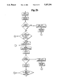
- FIG. 2a is a first portion of a flow diagram illustrating the steps performed in the calibration process
- FIG. 2b is a second portion of a flow diagram illustrating the steps performed in the calibration process.
- FIG. 2c is a third portion of a flow diagram illustrating the steps performed in the calibration process.
- FIG. 1 illustrates, in block diagram form, a system 8 in which the present invention is practiced.
- the system includes a computer console 10.
- the console 10 would comprise a personal computer of any appropriate type. It has been found that an IBM AT-type computer is appropriate for use in practicing the invention.
- the system 8 further, includes an IEEE 488 interface printed circuit board 12.
- the printed circuit board 12 plugs into the back of the computer console 10, as does a serial adaptor circuit board 14.
- a serial adaptor circuit board 14 Typically, an EIA 485 serial adaptor printed circuit board 14 would be employed.
- the IEEE 488 circuit board 12 is connected to a data acquisition subsystem 16. It is intended that a 3421 multiplex, 10-channel system be employed for this purpose.
- the system 8, further, employs a plurality of thermocouples 18.
- One thermocouple is embedded in an integrated circuit device, and each of such devices having a thermocouple embedded therein is positioned in one of a plurality of zones within a housing encircling the input tray of a handler device 19.
- ten zones are defined, and an integrated circuit device having a thermocouple embedded therein is positioned in each of these ten zones.
- a T-type thermocouple is appropriate for such use.
- the data acquisition subsystem 16 interfaces with each of the thermocouples 18. This is accomplished through connection and transmission cable 20.
- the data acquisition subsystem 16 also connects to the computer console 10. This is accomplished through the IEEE 488 interface cable 12.
- thermocouples embedded therein are, as previously discussed, placed at strategic locations throughout the input tray. The locations selected are functions of points at which temperature measurement is desired.
- the input tray is identified by a housing which encircles the tracks to define a sealed chamber.
- the temperature within the chamber is elevated or lowered, depending upon the environmental temperature at which integrated circuit devices to be tested are intended to ultimately operate. Temperature ranges can vary between as much as -55° C., at the low end, and +155° C., at the upper end. Any conventional means for effecting temperature variation, as known in the prior art, is appropriate.
- heating or cooling of the chamber is accomplished in order to create an environment similar to that, as previously discussed, in which the integrated circuits to be tested are to ultimately reside.
- the environment once created, receives the devices to be tested, and the devices "soak" within the environment for a period of time to allow them to achieve the temperature before they are singulated (that is, isolated) for transmission to the test site for interfacing with the tester apparatus.
- the serial adaptor board 14 is connected to a transceiver buffer board 22.
- the transceiver buffer board 22 is, in turn, connected to a temperature controller board 24 at the handler 19.
- thermocouples 18 During calibration, temperatures within the various zones of the handler input tray housing chamber are measured by employment of the thermocouples 18.
- the temperature sensed by the thermo couples are transmitted to the data acquisition subsystem 16 and, thereafter, to the computer console 10.
- the computer console 10 is programmed so as to receive information from the data acquisition subsystem 16, through the IEEE 488 interface board 12.
- the computer console 10 processes the received information and, automatically, in view of the programming, transmits, through the serial adaptor board 14, to the transceiver buffer board 22 actuation and control signals.
- the transceiver buffer board 22 in turn, translates a signal to allow temperature controller board 24 to initiate temperature changes.
- gas/electrical temperature control means are provided in the handler, those same means are employed for controlling temperature in the present system, in combination with the temperature controller board 24 as prompted by the computer console 10 via the transceiver buffer board 22. No additional retrofit of the existing handler 19 is necessary other than change of a single EPROM.
- the operator of the computer console 10 has a number of selections to input into the system 8.
- the internal structures for accommodating the devices will be different.
- hardware and fixtures for the handler 19 will vary depending upon whether DIP'S, SOIC'S, or some other type of integrated circuits are being tested.
- the hardware and fixtures will have previously been installed, and the operator makes a selection on the console 10 depending upon the hardware and fixtures being employed.
- the next selection deals with the size of the kit. As the choices vary in view of the type of integrated circuit being handled, they vary also in view of the size of device.
- the final initial step which must be manually implemented utilizing the present system is selecting the type of calibration. Basically two choices are available.
- the first choice is "standard calibration". This method of calibration enables the computer console 10 to calibrate for certain standard defined set points. For example, a standard calibration may involve calibration for +5° and -45°, verifying for -55°, calibrating for +75° and +125°, and verifying for +155°. It will be understood, however, that other calibration and verification temperatures could be defined as “standard calibration”. The specific temperatures could, of course, be programmed into the computer 10.
- the second type of calibration is "custom calibration". if this type of calibration is desired, the operator of the system must, in addition to selecting custom calibration, define, using the computer's keyboard, the number of calibration points, the set points, and the order of calibration. In the case of custom calibration, the various points are established each time set-up is initiated.
- FIG. 2a in the "custom calibration” branch, illustrates "A" in a circle. It will be noted that, after custom calibration is completed, the system jumps back to the same location in the flow path to place the system in a calibration mode.
- Offsets are inputs which result because of differences in temperatures ascertained by sensors 21 fixed within the equipment and those actually measured at the integrated circuits having the thermocouples embedded therein during a prior calibration. Frequently, it is desirable to start calibration with prior offsets remaining within the system. Quicker calibration may, thereby, result.
- the computer 10 having been programmed appropriately, responds to the decision with respect to the type of calibration (that is, standard calibration or custom calibration). Based upon that selection, the computer 10 will define the set points.
- the computer 10 will, at this point, initiate calibration at +5°. It will be noted that, in FIG. 2c, once calibration for one set point is completed, the system will loop back as indicated by the "D" in a circle. The system loops back to the "D” in a circle illustrated in FIG. 2a.
- a timer When calibrating to any particular set point, however, a timer is started. Typically, the timer would run for fifteen minutes. If the actual temperature sensed in a particular zone is +23°, and the system 8 were calibrating for a set point of +5°, assuming utilization of a gas/electrical heating system, a volume of gas would be "dumped" into the chamber to ensure cooling down of the location to a temperature below +5°, thereafter, electrical heaters will heat the chamber so as to tend to achieve the +5° temperature.
- the system reads the temperature sensed by the thermocouples 18 embedded in the integrated circuit devices at the designated zones (typically, ten zones).
- the system 8 reads the temperature sensed by fixed sensors 3 within the tray and displays it on the console 10.
- the screen is updated. If an error has occurred (for example, as evidenced by an open sensor), the computer console 10 can turn off the heat. The error is recorded and the flow goes to the "E" within the circle at the end of the flow diagram near the bottom in FIG. 2c.
- thermocouples 18 If the differential has achieved zero, calibration is automatically started.
- the computer 10 again reads the thermocouples 18 and "reads the display”. Errors are again checked for. If an error has occurred, the temperature is shut down, the error is recorded, and the system proceeds to the location on the flow diagram of "E" within a circle near the bottom of FIG. 2c.
- a second timer is employed for calibration. Typically, the second timer would run on a three-minute schedule. The system calibrates every three minutes. If the timer does not reach three minutes, the system jumps back up to the "C" within a circle immediately after the "start calibration" block near the center of FIG. 2b, and the calibration phase is performed again. The system will continue to operate within this loop until a three-minute period has elapsed (that is, until the calibration timer lapses).
- the system checks the thermocouple in each of the zones in order to ascertain actual temperature. If calibration is for +5° and a particular thermocouple senses +5.5°, the sensed condition is deemed unacceptable since, normally, calibration must be within + or -0.3° from the set point. Consequently, it will be determined that the system is calibrated to too hot a temperature.
- the computer 10 will, automatically, initiate actuation of the temperature controller board 24 to effect cooling in such a case.
- the actual temperature sensed is checked to be within the plus or minus 0.3° tolerance, and the other thermocouples 18 in different zones are also checked.
- the system 8 will, at this point in time, loop around sequentially a sufficient number of times until all zones are checked.
- the computer 10 starts a third timer to ensure that all zones stay within a range of the tolerance for a period of, for example, twelve minutes. If this does not occur, the system loops back to the "C" within a circle midway down in FIG. 2b, and calibration is reinitiated.
- the third timer is set for the period of time to ensure that the temperature in a particular zone does not vary more than + or -0.1° during the period of the timer. If variation of more than + or -0.1° occurs, the system loops back to the "C" within a circle midway down in FIG. 2b.
Landscapes
- Physics & Mathematics (AREA)
- General Physics & Mathematics (AREA)
- Engineering & Computer Science (AREA)
- Automation & Control Theory (AREA)
- Testing Of Individual Semiconductor Devices (AREA)
Abstract
Description
Claims (3)
Priority Applications (1)
| Application Number | Priority Date | Filing Date | Title |
|---|---|---|---|
| US07/702,945 US5287294A (en) | 1991-05-20 | 1991-05-20 | Apparatus and method for automatically calibrating for temperature an input tray of an integrated circuit handler |
Applications Claiming Priority (1)
| Application Number | Priority Date | Filing Date | Title |
|---|---|---|---|
| US07/702,945 US5287294A (en) | 1991-05-20 | 1991-05-20 | Apparatus and method for automatically calibrating for temperature an input tray of an integrated circuit handler |
Publications (1)
| Publication Number | Publication Date |
|---|---|
| US5287294A true US5287294A (en) | 1994-02-15 |
Family
ID=24823275
Family Applications (1)
| Application Number | Title | Priority Date | Filing Date |
|---|---|---|---|
| US07/702,945 Expired - Fee Related US5287294A (en) | 1991-05-20 | 1991-05-20 | Apparatus and method for automatically calibrating for temperature an input tray of an integrated circuit handler |
Country Status (1)
| Country | Link |
|---|---|
| US (1) | US5287294A (en) |
Cited By (7)
| Publication number | Priority date | Publication date | Assignee | Title |
|---|---|---|---|---|
| US5966940A (en) * | 1997-11-18 | 1999-10-19 | Micro Component Technology, Inc. | Semiconductor thermal conditioning apparatus and method |
| WO2000050848A1 (en) * | 1999-02-25 | 2000-08-31 | Redwood Microsystems, Inc. | Apparatus and method for correcting sensor drift |
| US6725180B2 (en) | 2001-01-12 | 2004-04-20 | Ingersoll-Rand Company | Environmental monitoring system |
| US20090000123A1 (en) * | 2005-03-21 | 2009-01-01 | SOCIéTé BIC | Shaving Device |
| WO2006093941A3 (en) * | 2005-03-01 | 2009-09-11 | Owen Oil Tools L.P. | Novel device and methods for firing perforating guns |
| US8449173B1 (en) * | 2008-04-10 | 2013-05-28 | Google Inc. | Method and system for thermal testing of computing system components |
| US9167242B1 (en) | 2010-05-04 | 2015-10-20 | Leif Meyer | Sensor measurement system and method |
Citations (9)
| Publication number | Priority date | Publication date | Assignee | Title |
|---|---|---|---|---|
| US4675826A (en) * | 1984-08-06 | 1987-06-23 | Granco-Clark, Inc. | Temperature control system |
| US4734872A (en) * | 1985-04-30 | 1988-03-29 | Temptronic Corporation | Temperature control for device under test |
| US4782445A (en) * | 1986-12-18 | 1988-11-01 | Food Automation-Service Techniques, Inc. | Control apparatus for cooking apparatus |
| US4817009A (en) * | 1987-08-19 | 1989-03-28 | Applied Automation, Inc. | Furnace zone temperature control |
| US4907177A (en) * | 1988-10-31 | 1990-03-06 | Grumman Aerospace Corporation | Computerized multi-zone crystal growth furnace precise temperature and heating control method |
| US4979134A (en) * | 1988-07-15 | 1990-12-18 | Minolta Camera Kabushiki Kaisha | Method for measuring surface temperature of semiconductor wafer substrate, and heat-treating apparatus |
| US4982347A (en) * | 1989-06-22 | 1991-01-01 | Unisys Corporation | Process and apparatus for producing temperature profiles in a workpiece as it passes through a belt furnace |
| US5012415A (en) * | 1989-01-06 | 1991-04-30 | Deere & Company | Control system calibration |
| US5025248A (en) * | 1989-09-01 | 1991-06-18 | Microthermo | Automatic temperature monitoring system |
-
1991
- 1991-05-20 US US07/702,945 patent/US5287294A/en not_active Expired - Fee Related
Patent Citations (9)
| Publication number | Priority date | Publication date | Assignee | Title |
|---|---|---|---|---|
| US4675826A (en) * | 1984-08-06 | 1987-06-23 | Granco-Clark, Inc. | Temperature control system |
| US4734872A (en) * | 1985-04-30 | 1988-03-29 | Temptronic Corporation | Temperature control for device under test |
| US4782445A (en) * | 1986-12-18 | 1988-11-01 | Food Automation-Service Techniques, Inc. | Control apparatus for cooking apparatus |
| US4817009A (en) * | 1987-08-19 | 1989-03-28 | Applied Automation, Inc. | Furnace zone temperature control |
| US4979134A (en) * | 1988-07-15 | 1990-12-18 | Minolta Camera Kabushiki Kaisha | Method for measuring surface temperature of semiconductor wafer substrate, and heat-treating apparatus |
| US4907177A (en) * | 1988-10-31 | 1990-03-06 | Grumman Aerospace Corporation | Computerized multi-zone crystal growth furnace precise temperature and heating control method |
| US5012415A (en) * | 1989-01-06 | 1991-04-30 | Deere & Company | Control system calibration |
| US4982347A (en) * | 1989-06-22 | 1991-01-01 | Unisys Corporation | Process and apparatus for producing temperature profiles in a workpiece as it passes through a belt furnace |
| US5025248A (en) * | 1989-09-01 | 1991-06-18 | Microthermo | Automatic temperature monitoring system |
Cited By (9)
| Publication number | Priority date | Publication date | Assignee | Title |
|---|---|---|---|---|
| US5966940A (en) * | 1997-11-18 | 1999-10-19 | Micro Component Technology, Inc. | Semiconductor thermal conditioning apparatus and method |
| WO2000050848A1 (en) * | 1999-02-25 | 2000-08-31 | Redwood Microsystems, Inc. | Apparatus and method for correcting sensor drift |
| US6725180B2 (en) | 2001-01-12 | 2004-04-20 | Ingersoll-Rand Company | Environmental monitoring system |
| US20040204881A1 (en) * | 2001-01-12 | 2004-10-14 | Ingersoll-Rand Company | Environmental monitoring system |
| WO2006093941A3 (en) * | 2005-03-01 | 2009-09-11 | Owen Oil Tools L.P. | Novel device and methods for firing perforating guns |
| US20090000123A1 (en) * | 2005-03-21 | 2009-01-01 | SOCIéTé BIC | Shaving Device |
| US7996994B2 (en) | 2005-03-21 | 2011-08-16 | Societe Bic | Shaving device |
| US8449173B1 (en) * | 2008-04-10 | 2013-05-28 | Google Inc. | Method and system for thermal testing of computing system components |
| US9167242B1 (en) | 2010-05-04 | 2015-10-20 | Leif Meyer | Sensor measurement system and method |
Similar Documents
| Publication | Publication Date | Title |
|---|---|---|
| US7461535B2 (en) | Multi-temperature programming for accelerometer | |
| TWI870609B (en) | Calibration arrangement and corresponding calibration method and calibration apparatus | |
| US6023985A (en) | Controller for an environmental test chamber | |
| US5659125A (en) | Automatic calibration method for carbon monoxide monitors | |
| US5287294A (en) | Apparatus and method for automatically calibrating for temperature an input tray of an integrated circuit handler | |
| US6035721A (en) | Process for compensating for the incorrect operation of measuring devices caused by external influences | |
| CN111721444B (en) | Mass production method and system for calibrating temperature sensor chip | |
| WO1988006796A1 (en) | Reactor control system verification | |
| US10359321B2 (en) | On-chip circuit and method for accurately measuring die temperature of an integrated circuit | |
| US5884236A (en) | Calibration method of IC tester | |
| CN106371001A (en) | Device and method for controlling test temperature of chip to be tested | |
| US6032107A (en) | Calibrating test equipment | |
| US6897646B2 (en) | Method for testing wafers to be tested and calibration apparatus | |
| US20060095221A1 (en) | Method and apparatus for controlling variable delays in electronic circuitry | |
| CN111366837B (en) | Calibration method and system for mass production of self-adaptive temperature chips | |
| US20030020488A1 (en) | Electronic component, tester device and method for calibrating a tester device | |
| US8751183B2 (en) | Tester having system maintenance compliance tool | |
| CN119596103A (en) | Chip rapid over-temperature test system and test method | |
| CN109001534B (en) | Aircraft activation resistance measurement system and method | |
| US20040059507A1 (en) | Analysis apparatus and analysis method | |
| US6560556B1 (en) | Non-invasive process for circuit defect isolation using thermal expansion property of thermodynamics | |
| US6329833B1 (en) | System and method for automatically measuring input voltage levels for integrated circuits | |
| US7282938B2 (en) | Testing apparatus and method for providing temperature stress to electronic component | |
| JPH0727809A (en) | Calibration of measuring system in automatic testing apparatus for surface-mounting type crystal device | |
| CN119667429A (en) | A method and system for establishing a wafer test temperature environment |
Legal Events
| Date | Code | Title | Description |
|---|---|---|---|
| AS | Assignment |
Owner name: MICRO COMPONENT TECHNOLOGY, INC.,, MINNESOTA Free format text: ASSIGNMENT OF ASSIGNORS INTEREST.;ASSIGNORS:BAERT, VICTOR R.;ELFSTROM, SCOTT D.;WILLIAMS, TEDDY P.;REEL/FRAME:005898/0677 Effective date: 19911017 |
|
| AS | Assignment |
Owner name: HAMBRECHT & QUIST GUARANTY FINANCE Free format text: SECURITY INTEREST;ASSIGNOR:MICRO COMPONENT TECHNOLOGY, INC. A CORP. OF DELAWARE;REEL/FRAME:006187/0793 Effective date: 19920710 |
|
| AS | Assignment |
Owner name: MICRO COMPONENT TECHNOLOGY, INC., MINNESOTA Free format text: RELEASE OF SECURITY INTEREST IN PATENTS, EXHIBIT 1, AND SCHEDULE X;ASSIGNOR:HAMBRACHT & QUIST GUARANTY FINANCE;REEL/FRAME:007470/0659 Effective date: 19950412 |
|
| FPAY | Fee payment |
Year of fee payment: 4 |
|
| AS | Assignment |
Owner name: NORWEST BANK MINNESOTA, NATIONAL ASSOCATION, MINNE Free format text: SECURITY AGREEMENT;ASSIGNOR:MICRO COMPONENT TECHNOLOGY, INC.;REEL/FRAME:009015/0834 Effective date: 19980217 |
|
| AS | Assignment |
Owner name: NORWEST BUSINESS CREDIT, INC., MINNESOTA Free format text: SECURITY AGTREEMENT;ASSIGNOR:MICRO COMPONENT TECHNOLOGY, INC. A CORP. OF MINNESOTA;REEL/FRAME:009038/0235 Effective date: 19980217 |
|
| REMI | Maintenance fee reminder mailed | ||
| FPAY | Fee payment |
Year of fee payment: 8 |
|
| SULP | Surcharge for late payment |
Year of fee payment: 7 |
|
| AS | Assignment |
Owner name: SILICON VALLEY BANK, CALIFORNIA Free format text: SECURITY INTEREST;ASSIGNOR:MICRO COMPONENT TECHNOLOGY INC;REEL/FRAME:014438/0974 Effective date: 20030610 |
|
| REMI | Maintenance fee reminder mailed | ||
| LAPS | Lapse for failure to pay maintenance fees | ||
| STCH | Information on status: patent discontinuation |
Free format text: PATENT EXPIRED DUE TO NONPAYMENT OF MAINTENANCE FEES UNDER 37 CFR 1.362 |
|
| FP | Lapsed due to failure to pay maintenance fee |
Effective date: 20060215 |
|
| AS | Assignment |
Owner name: LAURUS MASTER FUND, LTD., NEW YORK Free format text: GRANT OF SECURITY INTEREST IN PATENTS AND TRADEMARKS;ASSIGNOR:MICRO COMPONENT TECHNOLOGY, INC.;REEL/FRAME:019265/0285 Effective date: 20070329 |
|
| AS | Assignment |
Owner name: MICRO COMPONENT TECHNOLOGY, INC., MINNESOTA Free format text: ASSIGNMENT OF ASSIGNORS INTEREST;ASSIGNOR:MICRO COMPONENT TECHNOLOGY, INC.;REEL/FRAME:019744/0835 Effective date: 20070806 |
|
| AS | Assignment |
Owner name: MCT WORLDWIDE, LLC, MINNESOTA Free format text: ASSIGNMENT OF ASSIGNORS INTEREST;ASSIGNOR:MCT, INC.;REEL/FRAME:022634/0743 Effective date: 20090421 |
|
| AS | Assignment |
Owner name: LV ADMINISTRATIVE SERVICES, INC., NEW YORK Free format text: GRANT OF SECURITY INTEREST IN PATENTS AND TRADEMARKS;ASSIGNOR:MCT WORLDWIDE, LLC;REEL/FRAME:023419/0228 Effective date: 20091016 |