US528177A - Cotton elevator and distributer - Google Patents
Cotton elevator and distributer Download PDFInfo
- Publication number
- US528177A US528177A US528177DA US528177A US 528177 A US528177 A US 528177A US 528177D A US528177D A US 528177DA US 528177 A US528177 A US 528177A
- Authority
- US
- United States
- Prior art keywords
- cotton
- separator box
- openings
- suction
- trough
- Prior art date
- Legal status (The legal status is an assumption and is not a legal conclusion. Google has not performed a legal analysis and makes no representation as to the accuracy of the status listed.)
- Expired - Lifetime
Links
- 229920000742 Cotton Polymers 0.000 title description 36
- 238000007599 discharging Methods 0.000 description 4
- 238000010276 construction Methods 0.000 description 2
- 238000012550 audit Methods 0.000 description 1
- 230000003028 elevating effect Effects 0.000 description 1
Images

Classifications
-
- B—PERFORMING OPERATIONS; TRANSPORTING
- B22—CASTING; POWDER METALLURGY
- B22D—CASTING OF METALS; CASTING OF OTHER SUBSTANCES BY THE SAME PROCESSES OR DEVICES
- B22D30/00—Cooling castings, not restricted to casting processes covered by a single main group
-
- B—PERFORMING OPERATIONS; TRANSPORTING
- B65—CONVEYING; PACKING; STORING; HANDLING THIN OR FILAMENTARY MATERIAL
- B65G—TRANSPORT OR STORAGE DEVICES, e.g. CONVEYORS FOR LOADING OR TIPPING, SHOP CONVEYOR SYSTEMS OR PNEUMATIC TUBE CONVEYORS
- B65G51/00—Conveying articles through pipes or tubes by fluid flow or pressure; Conveying articles over a flat surface, e.g. the base of a trough, by jets located in the surface
- B65G51/04—Conveying the articles in carriers having a cross-section approximating that of the pipe or tube; Tube mail systems
- B65G51/26—Stations
Definitions
- This invention relates to cotton elevators and distributors; and it has for its object to provide certain improvements in apparatus of this character whereby cotton may be convenien tly and readily elevated from the store house or wagon,'and evenly distributed to any number of gins which may be arranged successively in the same row.
- the main and primary objects of the present invention are to provide for the elevation and conveying of cotton from a. wagon or store house by atmospheric suction, completely separating the cotton from the current of air carrying the same, and then distributing it into the gins, and to provide simple and efficient devices for accomplishing these results.
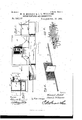
- Figure 1- is a side elevation of a cotton elevating and distributing apparatus constructed in accordance with this invention. Shown in connection with several gin stands into which the cotton is fed.
- Fig. 2 is a central vertical longitudinal sectional view of the apparatus.
- Fig. 3 is a vertical transverse sectional view thereof.
- Fig. 4 is a detail in perspective of the horizontally reciprocating separating screen with its attached dividing valve board.
- Fig. 5 is an enlargeddetail in perspective of a portion of the distributer trough showing the connections of the pitmen with the dis-. tributing devices therein.
- Fig. 6 is a detail in perspective of a portion of the horizontally sliding distributing frame and the self-ad. justing push racks thereon.
- Fig. 7 isa detail sectional View on the line m-a; of Fig. 2.
- a suitable inclosed casing which is supported by means of any suitable supports in a conwith the diametrically opposite inlet and 621-.
- haust openings B which openings areforined centrally in the opposite sides of the box and ata point near the top thereof.
- One of the openings B is adapted to receive one end of the supply pipe '0, whichis closely fitted into such opening to form an air tight joint therein, and is adapted to be led from the store-house, the wagon or other point at which the cotton to be ginned may be located, and such cotton is adapted to be drawn through the supply pipe G, undera tmospherio suction, and discharged through the inlet opening of the separator box, into such box.
- the opposite opening B which is the exhaust opening of the separator box, snugly receives one end of a suction pipe D, which pipe D, leads to an ordinary suction fan (not shown), which is designed to createa sufficient draft or suction to draw a supply of cotton through the pipe 0, and into the separator box.
- Theseparator box A is provided at a point directly below and near to the inlet and exhaust openings with a short intermediate bottom board E, the ends of which terminate short of the oppositeends of the box casing to form the end discharge pockets F, located at opposite ends of the separator box.
- cotton discharge pockets F, of the separator box are inclosed each by a pair of automatic discharge valves G.
- valves G of each pair which inclose the end discharge openings ot the separator box, are hinged at their upper edges at g, to the ends of the bottom lboard E, and a directlyopposite point on the end walls of the box casing, respectively, and when closed the valves of each pair are disposed at an angleso that their lower ends meet each other to close in the intervening space or pocket between the ends of the hot- The end tom board and the ends of the box casing.
- a rectangular screen frame H Arranged to reciprocate horizontally within the separator box A, over the short intermediate bottom board E, thereof and over the opening next to the fan pipe D, is a rectangular screen frame H.
- the screen frame H is constructed of suitable strength material and of a size so that it will have a free movement between the top and bottom of such separator box, and to one side of the screen frame H, is attached a separator screen I, which serves to intercept the cotton discharged into the separator box from the inlet opening, while at the same time permitting the air to circulate therethrough and into the suction pipe D.
- the horizontally reciprocating screen frame H is disposed vertically within the separator box A, and has securely attached to one side and the center of the same the off-standing dividing valve board J.
- the off-standing dividing valve board J, and the reciprocating screen frame carrying the same are of a width and height to completely occupy the space inclosed by the opposite sides and top and bottom of the separator box, whereby the valve board may alternately out ed the suction from the opposite end discharge pockets F, and thereby provide means for alternately discharging the cotton out of such end pockets.
- the reciprocating screen frame H has extended from one lower end thereof the slide arm K, moving through a guide opening is, in one end of the separator box and provided in its outer exposed end with a slot is, the function of Which will presently appear, while from the corresponding opposite end of the screen frame is extended a shorter guide arm L moving in a guide opening 1, disposed opposite the guide opening is.
- the sliding screen frame intercepts the cotton coming in with the air currents from the supply pipe, and its alternate movement from end to end presents continuously a clean and open screen to the air current by reason of the dividing valve board, which at each reciprocation passes beyond the aligned openings B, and cuts 01f one of the discharging pockets F, from the air suction and from the feed of the cotton into the separator box.
- the separator box A In order to relieve the opposite discharge pockets F, from excessive suction and thereby provide for the easy and rapid opening of the valves G, the separator box A, is provided in one side above each of the pockets F, with the relief valve openings W.
- the relief valve openings W provide for the admission of the outer air into the discharge pockets at the moment such pockets are cut off from the suction of the fan so that the valves G, will instantly open.
- valve boxes or brackets w Attached to the outside of the separator box A, over each of the openings W, are the off-standing valve boxes or brackets w, provided at their outer edges with inclined valve seats X, over which are adapted to work the automatic relief valves Y, hinged at their upper edges, as at y, to the outer upper edges of the valve brackets, and being thereby suspended in a position which insures the automatic opening thereof when relieved from the fan suction within the pockets F.
- the distributing trough M is an opentrough which is suitably secured in position directly under the separator box A, in order to receive the cotton discharged from such box, and said distributing trough extends beyond the box over any number of gin stands which are to be fed, and at points directly over the gin stands that are arranged successively in the same row the distributing trough is provided with bottom feed openings m, through which the cotton falls into the gin as it is fed along throughout the entire length of the trough.
- the trough M is of course open at the top only, to receive the cotton from the separator box A, and it accommodates therein the horizontally sliding or reciprocating distributing frame N.
- the distributing frame N is arranged to slide inside and at the top of the trough and extends throughout the entire length of such trough in order to properly feed the cotton along the trough and into the gins arranged thereunder, and said distributing frame comprises the parallel side bars a, connected by the transverse cross bars 0, which are preferably secured to the lower sides of said bars in order to act in the capacity of stop bars for the pivoted 0r self-adjusting push racks P.
- the self -adjusting push racks P are ar ranged at regularly spaced distances apart from each other and comprise the pivoted rack bars 10, and a series of feeding fingers 19', secured at one end to said bars and working inside of the trough.
- the rack bars 23, are provided with pivot ends 19 which are journaledin the opposite side bars n, of the distributing frame, directly over and at one side of the transverse stop bars 0, thereby allowing the push racks to normally assume a vertical position at one side of the stop bars,
- the reciprocating distributing frame N has secured to the top thereof at suitable points between its ends the transverse bear ing or supporting bars Q, provided with spindle ends q, to receive the traveling rollers R,
- crank shaft T is journaled in the bearing extensions t, formed by projecting the sides of the trough beyond one end of the separator box, and such crank shaft carries intermediate of its ends the drive pulley U, which receives motion from a suitable power and transmits it to the sev-- eral parts of the apparatus.
- the length of the slide arm K, and the slot therein is properly adjusted with relation to the movement of the distributing frame in order to insure the proper operation of the several parts of the apparatus, sothat as the distributing frame moves in one direction it will move the screen frame the proper distance in the same direction, and vice versa, and since the travel of the separator screen frame is slightly less than that of the distributin g frame, the length of the slot is equal
- the transverse stop bars 0 On the reverse ing away from the transverse stop bars 0, so that just as the carriage begins its next forward movement such push racks fall into their vertical pushing position behind the cotton over which they have trailed, so that the cotton will be continuously fed along the trough and into the gins under the same, and any excess of supply beyond the capacity of the gins is pushed forward and out at the farthest end of the trough.
- an inclosed separator box having opposite suction supply and exhaust pipes, and end discharge openings at the bottom, suction-closed valves located in said discharge openings, a device for intercepting and discharging the cotton arranged to reciprocate between the discharge openings and from side to side of the opposite suction supply and exhaust pipes to alternately cut off the suction from said discharge openings, and distributing devices arranged under the discharge of said separator box, substantially asset forth.
- an inclosed separator box having opposite aligned openings, suction supply and exhaust pipes connected with the opposite openings of the separator box, opposite end suctionclosed discharge valves, and a separating screen arranged to reciprocate within theseparator box at one side of the exhaust opening therein, and provided with a valve board car'- ried thereby substantially as set forth.
- an inclosed separator box having end discharge pockets and opposite aligned openings, suction supply andexhaust pipes connected with said openings, valves for said discharge pockets, a vertically disposed screen frame arranged to reciprocate within the separator box over the exhaust opening thereof and provided with a wire screen covering and IIO a central dividing valve board projected cenadapted to have their lower ends closed against each other by the air suction maintained within the separator box, a vertically disposed separator screen arranged to reciprocate Within the separator box over its exhaust opening and provided with a central ofi-standing dividing valve board sliding on the bottom of the box between the opposite end openings, means for reciprocating said screen frame, and suitable distributing devices substantially as set forth.
- a cotton handling apparatus the combination with the pneumatic supply devices; of an open distributing trough provided at suitable points with feed openings, a frame or carriage arranged to slide within the trough and provided with transverse stop bars, a spaced series of push racks comprising rackbars pivoted to the frame or carriage above and to one side of the stop bars and feed fingers secured in such rack bars at one end, bearing or supporting bars secured to the top of the frame or carriage and having roller spindles at their ends, rollers journaled 0n said'spindles and traveling on the upper edges of said trough, and means for reciprocating said frame or carriage, substantiallyas set forth.
- an inclosed separator box having a suction pipe connected'therewithand opposite valved discharge openings at the bottom and opposite ends thereof, automatically opening and closing suction relief valves arranged above each valved opening, a cotton separating and shifting device arranged to reciprocate between the discharge openings, and suitable distributing-devices below said openings, substantially as set forth.
- a separator box having opposite aligned suctionsupply and exhaust openings; valved discharge pockets at the opposite ends thereof, and relief valve openings in one side above each pocket, inclined valve brackets attached to the separator box over each relief valve opening, automatically opening and closing suction relief valves hinged to the valve brackets and adapted to cover and uncover the relief valve openings, a cotton separating and shifting device arranged to reciprocate between the discharge openings, and distributing devices below said openings, substantially as set forth.
Landscapes
- Engineering & Computer Science (AREA)
- Mechanical Engineering (AREA)
- Physics & Mathematics (AREA)
- Fluid Mechanics (AREA)
- Preliminary Treatment Of Fibers (AREA)
Description
(Ho M0551.)
2 Sheetssheet 1.
OFPITTT & J. L. WILLIAMS,
' 'GOTTON ELEVATOR AND DISTRIBUTER.
Patented octso, 1894.'
l zz zz lzzzzl llmg V 199a 1316 vs Mal- 0 Mm Jam-6317, Wham;
UNITED STATES WILLIAM EQMOFFITT AND JAMES L.
COTTO N ELEVATOR WILLIAMS, OF-PILOT POINT, TEXAS.
AND DISTRIBUTER.
SPECIFICATION forming part of Letters Patent No. 528,177, dated October 30, 1894.
Application filed November 17, 1893. Serial No. 491373- 1N0 model.
To all whom it may concern: 7
Be it known that we, WILLIAM E. Monrrr'r and JAMES L.WILLIAMS, citizens of the United States, residing at Pilot Point, in the county of Denton and State of Texas, have invented a new and useful Cotton Elevator and Distributor, of which the following is a specification.
This invention relates to cotton elevators and distributors; and it has for its object to provide certain improvements in apparatus of this character whereby cotton may be convenien tly and readily elevated from the store house or wagon,'and evenly distributed to any number of gins which may be arranged successively in the same row.
To this end the main and primary objects of the present invention are to provide for the elevation and conveying of cotton from a. wagon or store house by atmospheric suction, completely separating the cotton from the current of air carrying the same, and then distributing it into the gins, and to provide simple and efficient devices for accomplishing these results.
With these and other objects in view which will readily appear as the nature of the invention is better understood the same consists in the novel construction, combination and arrangement of parts hereinafter more fully described, illustrated and claimed.
In the accompanying drawings:Figure 1- is a side elevation of a cotton elevating and distributing apparatus constructed in accordance with this invention. Shown in connection with several gin stands into which the cotton is fed. Fig. 2 is a central vertical longitudinal sectional view of the apparatus. Fig. 3 is a vertical transverse sectional view thereof. Fig. 4 is a detail in perspective of the horizontally reciprocating separating screen with its attached dividing valve board. Fig. 5 is an enlargeddetail in perspective of a portion of the distributer trough showing the connections of the pitmen with the dis-. tributing devices therein. Fig. 6 is a detail in perspective of a portion of the horizontally sliding distributing frame and the self-ad. justing push racks thereon. Fig. 7 isa detail sectional View on the line m-a; of Fig. 2.
Referring to the accompanying drawings, A
a suitable inclosed casing which is supported by means of any suitable supports in a conwith the diametrically opposite inlet and 621-. haust openings B, which openings areforined centrally in the opposite sides of the box and ata point near the top thereof.
One of the openings B,is adapted to receive one end of the supply pipe '0, whichis closely fitted into such opening to form an air tight joint therein, and is adapted to be led from the store-house, the wagon or other point at which the cotton to be ginned may be located, and such cotton is adapted to be drawn through the supply pipe G, undera tmospherio suction, and discharged through the inlet opening of the separator box, into such box. The opposite opening B, which is the exhaust opening of the separator box, snugly receives one end of a suction pipe D, which pipe D, leads to an ordinary suction fan (not shown), which is designed to createa sufficient draft or suction to draw a supply of cotton through the pipe 0, and into the separator box.
Theseparator box A, is provided at a point directly below and near to the inlet and exhaust openings with a short intermediate bottom board E, the ends of which terminate short of the oppositeends of the box casing to form the end discharge pockets F, located at opposite ends of the separator box. cotton discharge pockets F, of the separator box are inclosed each bya pair of automatic discharge valves G. The valves G, of each pair which inclose the end discharge openings ot the separator box, are hinged at their upper edges at g, to the ends of the bottom lboard E, and a directlyopposite point on the end walls of the box casing, respectively, and when closed the valves of each pair are disposed at an angleso that their lower ends meet each other to close in the intervening space or pocket between the ends of the hot- The end tom board and the ends of the box casing.
It will of course be understood that when the air suction is maintained throughout the suprepresents a cotton separator box comprising ply and the suction pipes and the separator box, such automatic discharge valves are kept closed by reason of such suction, but when the suction is shut off from either of the end pockets the valves of their own weight, together with the weight of the cotton contained in the pockets, naturally open to discharge the cotton.
Arranged to reciprocate horizontally within the separator box A, over the short intermediate bottom board E, thereof and over the opening next to the fan pipe D, is a rectangular screen frame H. The screen frame H, is constructed of suitable strength material and of a size so that it will have a free movement between the top and bottom of such separator box, and to one side of the screen frame H, is attached a separator screen I, which serves to intercept the cotton discharged into the separator box from the inlet opening, while at the same time permitting the air to circulate therethrough and into the suction pipe D. The horizontally reciprocating screen frame H, is disposed vertically within the separator box A, and has securely attached to one side and the center of the same the off-standing dividing valve board J. p
The off-standing dividing valve board J, and the reciprocating screen frame carrying the same are of a width and height to completely occupy the space inclosed by the opposite sides and top and bottom of the separator box, whereby the valve board may alternately out ed the suction from the opposite end discharge pockets F, and thereby provide means for alternately discharging the cotton out of such end pockets. The reciprocating screen frame H, has extended from one lower end thereof the slide arm K, moving through a guide opening is, in one end of the separator box and provided in its outer exposed end with a slot is, the function of Which will presently appear, while from the corresponding opposite end of the screen frame is extended a shorter guide arm L moving in a guide opening 1, disposed opposite the guide opening is. I Now it will be apparent that the sliding screen frame intercepts the cotton coming in with the air currents from the supply pipe, and its alternate movement from end to end presents continuously a clean and open screen to the air current by reason of the dividing valve board, which at each reciprocation passes beyond the aligned openings B, and cuts 01f one of the discharging pockets F, from the air suction and from the feed of the cotton into the separator box. It will also be apparent thatjust as soon as the suction has been relieved from one of the discharge pockets, the valves of such pocket will open and allow the cotton to fall into the distributing trough M, arranged under the separator box, but just as soon as the reciprocating screen frame carries the valve board to the opposite side of the air openings, the upward suction instantly closes the valves which have just opened, so that a fresh quantity of cotton may be discharged through the same on the return movement of the screen audits dividing valve board.
In order to relieve the opposite discharge pockets F, from excessive suction and thereby provide for the easy and rapid opening of the valves G, the separator box A, is provided in one side above each of the pockets F, with the relief valve openings W. The relief valve openings W, provide for the admission of the outer air into the discharge pockets at the moment such pockets are cut off from the suction of the fan so that the valves G, will instantly open. Attached to the outside of the separator box A, over each of the openings W, are the off-standing valve boxes or brackets w, provided at their outer edges with inclined valve seats X, over which are adapted to work the automatic relief valves Y, hinged at their upper edges, as at y, to the outer upper edges of the valve brackets, and being thereby suspended in a position which insures the automatic opening thereof when relieved from the fan suction within the pockets F.
It will be apparent that by reason of the excessive length of the supply pipe 0, or by reason of the excessive quantity of cotton being fed into the supply pipe, it may be necessary to put such excessive suction pressure upon the double discharge valves G, as will prevent them from easily opening and discharging the cotton, but just as soon as the valve board cuts off one pocket from the air cylinder, the relief valve for that pocket opens and relieves the same of any excess of pressure so that the valves G, easily open.
The distributing trough M, is an opentrough which is suitably secured in position directly under the separator box A, in order to receive the cotton discharged from such box, and said distributing trough extends beyond the box over any number of gin stands which are to be fed, and at points directly over the gin stands that are arranged successively in the same row the distributing trough is provided with bottom feed openings m, through which the cotton falls into the gin as it is fed along throughout the entire length of the trough. The trough M, is of course open at the top only, to receive the cotton from the separator box A, and it accommodates therein the horizontally sliding or reciprocating distributing frame N.
The distributing frame N, is arranged to slide inside and at the top of the trough and extends throughout the entire length of such trough in order to properly feed the cotton along the trough and into the gins arranged thereunder, and said distributing frame comprises the parallel side bars a, connected by the transverse cross bars 0, which are preferably secured to the lower sides of said bars in order to act in the capacity of stop bars for the pivoted 0r self-adjusting push racks P.
The self -adjusting push racks P, are ar ranged at regularly spaced distances apart from each other and comprise the pivoted rack bars 10, and a series of feeding fingers 19', secured at one end to said bars and working inside of the trough. The rack bars 23, are provided with pivot ends 19 which are journaledin the opposite side bars n, of the distributing frame, directly over and at one side of the transverse stop bars 0, thereby allowing the push racks to normally assume a vertical position at one side of the stop bars,
while also allowing the same to lift up when the distributing frame reciprocates in one direction.
The reciprocating distributing frame N, has secured to the top thereof at suitable points between its ends the transverse bear ing or supporting bars Q, provided with spindle ends q, to receive the traveling rollers R,
loosely connected to the cranks of the crank arms 3, carried on the opposite extremities of the crank shaft T. The crank shaft T, is journaled in the bearing extensions t, formed by projecting the sides of the trough beyond one end of the separator box, and such crank shaft carries intermediate of its ends the drive pulley U, which receives motion from a suitable power and transmits it to the sev-- eral parts of the apparatus.
Arising from one of the sidebars of the dis tribnting frame N, at a point beyond one end of the separator box A, is the upright push arm or rod V, securely braced to the distributing frame by the brace v,and having its upper end working in the slotted end-of the slide arm K, of the reciprocating screen frame. The length of the slide arm K, and the slot therein, is properly adjusted with relation to the movement of the distributing frame in order to insure the proper operation of the several parts of the apparatus, sothat as the distributing frame moves in one direction it will move the screen frame the proper distance in the same direction, and vice versa, and since the travel of the separator screen frame is slightly less than that of the distributin g frame, the length of the slot is equal On the reverse ing away from the transverse stop bars 0, so that just as the carriage begins its next forward movement such push racks fall into their vertical pushing position behind the cotton over which they have trailed, so that the cotton will be continuously fed along the trough and into the gins under the same, and any excess of supply beyond the capacity of the gins is pushed forward and out at the farthest end of the trough.
Changes in the form, proportion and the minor details of construction may be resorted to without departing from the principle or sacrificing any of the advantages of this invention.
Having thus described the invention, what is claimed,and desired to be secured by Letters Patent, is l 1. In a cotton elevator and distributer, an inclosed separator box having opposite suction supply and exhaust pipes, and end discharge openings at the bottom, suction-closed valves located in said discharge openings, a device for intercepting and discharging the cotton arranged to reciprocate between the discharge openings and from side to side of the opposite suction supply and exhaust pipes to alternately cut off the suction from said discharge openings, and distributing devices arranged under the discharge of said separator box, substantially asset forth.
2. In an apparatus of the class described, an inclosed separator box having opposite aligned openings, suction supply and exhaust pipes connected with the opposite openings of the separator box, opposite end suctionclosed discharge valves, and a separating screen arranged to reciprocate within theseparator box at one side of the exhaust opening therein, and provided with a valve board car'- ried thereby substantially as set forth.
8. In an apparatus of the class described, an inclosed separator box having end discharge pockets and opposite aligned openings, suction supply andexhaust pipes connected with said openings, valves for said discharge pockets, a vertically disposed screen frame arranged to reciprocate within the separator box over the exhaust opening thereof and provided with a wire screen covering and IIO a central dividing valve board projected cenadapted to have their lower ends closed against each other by the air suction maintained within the separator box, a vertically disposed separator screen arranged to reciprocate Within the separator box over its exhaust opening and provided with a central ofi-standing dividing valve board sliding on the bottom of the box between the opposite end openings, means for reciprocating said screen frame, and suitable distributing devices substantially as set forth.
5. In an apparatus of the class described, the combination with a suitable cotton sup ply; of an open cotton distributing trough provided at suitable points with bottom feed openings, and a rack carriage mounted to slide within said open trough and provided with a regularly spaced series of pivotally supported push racks working inside of the trough, and stops arranged at one side of the push racks substantially as set forth.
6. In a cotton handling apparatus, the combination with the pneumatic supply devices; of an open distributing trough provided at suitable points with feed openings, a frame or carriage arranged to slide within the trough and provided with transverse stop bars, a spaced series of push racks comprising rackbars pivoted to the frame or carriage above and to one side of the stop bars and feed fingers secured in such rack bars at one end, bearing or supporting bars secured to the top of the frame or carriage and having roller spindles at their ends, rollers journaled 0n said'spindles and traveling on the upper edges of said trough, and means for reciprocating said frame or carriage, substantiallyas set forth.
7. In an apparatus of the class described,-
the combination of an inclosed separator box having a suction pipe connected'therewithand opposite valved discharge openings at the bottom and opposite ends thereof, automatically opening and closing suction relief valves arranged above each valved opening, a cotton separating and shifting device arranged to reciprocate between the discharge openings, and suitable distributing-devices below said openings, substantially as set forth.
8. In an apparatus of the class described, the combination of a separator box having opposite aligned suctionsupply and exhaust openings; valved discharge pockets at the opposite ends thereof, and relief valve openings in one side above each pocket, inclined valve brackets attached to the separator box over each relief valve opening, automatically opening and closing suction relief valves hinged to the valve brackets and adapted to cover and uncover the relief valve openings, a cotton separating and shifting device arranged to reciprocate between the discharge openings, and distributing devices below said openings, substantially as set forth.
9. In an apparatus of the class described, the combination of the separator box having bottom discharge openings, the reciprocating valve screen arranged within the separator box and having aslotted slide arm moving through the box, an open distributing trough arranged under the separator box, and a distributing rack mounted to slide within said trough and having an upright push arm arranged to work in the slot of said slide arm, substantially as set forth.
In testimony that We claim the foregoing as our own, we have hereto affixed our signatures in the presence of two Witnesses.
WILLIAM E. MOFFIIT. JAMES L. WILLIAMS. Witnesses:
H. A. HALE, F. O. BLACKWELL.
Publications (1)
| Publication Number | Publication Date |
|---|---|
| US528177A true US528177A (en) | 1894-10-30 |
Family
ID=2596965
Family Applications (1)
| Application Number | Title | Priority Date | Filing Date |
|---|---|---|---|
| US528177D Expired - Lifetime US528177A (en) | Cotton elevator and distributer |
Country Status (1)
| Country | Link |
|---|---|
| US (1) | US528177A (en) |
-
0
- US US528177D patent/US528177A/en not_active Expired - Lifetime
Similar Documents
| Publication | Publication Date | Title |
|---|---|---|
| US528177A (en) | Cotton elevator and distributer | |
| US1173073A (en) | Pneumatic conveyer. | |
| US1225403A (en) | Apparatus for cleaning and drying grain. | |
| US705310A (en) | Pneumatic conveyer. | |
| US485571A (en) | Heman a | |
| US588812A (en) | bessonette | |
| US655299A (en) | Pneumatic cotton elevator and distributer. | |
| US1230757A (en) | Device for reclaiming grain. | |
| US633561A (en) | Pneumatic stacker. | |
| US453551A (en) | Svilliam e | |
| US610667A (en) | Seed-cotton distributer and cleaner | |
| US231376A (en) | Apparatus for catching dust generated in middlings-purifiers | |
| US651986A (en) | Cotton separator, distributer, and feeder. | |
| US146464A (en) | Improvement in middlings-purifiers | |
| US1054765A (en) | Dehydrating apparatus. | |
| US694540A (en) | Grain-cleaner. | |
| US633479A (en) | Cotton-distributer. | |
| USRE6198E (en) | Improvement in flour-bolts | |
| US732545A (en) | Hot-coke conveyer. | |
| US392321A (en) | Straw-carrier for thrashing-machines | |
| US547516A (en) | gammons- | |
| US311189A (en) | Bronzing machine | |
| US518315A (en) | And cleaning seed cotton | |
| US902921A (en) | Cotton elevator and distributer. | |
| US291151A (en) | Thrasher |