US527664A - Driving mechanism for drawing-off rollers of combing-machines - Google Patents
Driving mechanism for drawing-off rollers of combing-machines Download PDFInfo
- Publication number
- US527664A US527664A US527664DA US527664A US 527664 A US527664 A US 527664A US 527664D A US527664D A US 527664DA US 527664 A US527664 A US 527664A
- Authority
- US
- United States
- Prior art keywords
- shaft
- rollers
- roller
- apron
- shafts
- Prior art date
- Legal status (The legal status is an assumption and is not a legal conclusion. Google has not performed a legal analysis and makes no representation as to the accuracy of the status listed.)
- Expired - Lifetime
Links
- 230000007246 mechanism Effects 0.000 title description 8
- 239000000835 fiber Substances 0.000 description 5
- 230000009471 action Effects 0.000 description 2
- 238000010276 construction Methods 0.000 description 2
- 239000000463 material Substances 0.000 description 2
- 101100379080 Emericella variicolor andB gene Proteins 0.000 description 1
- 239000010985 leather Substances 0.000 description 1
- 230000004048 modification Effects 0.000 description 1
- 238000012986 modification Methods 0.000 description 1
- 230000002093 peripheral effect Effects 0.000 description 1
- 230000002035 prolonged effect Effects 0.000 description 1
- 230000009467 reduction Effects 0.000 description 1
- 230000001105 regulatory effect Effects 0.000 description 1
Images
Classifications
-
- D—TEXTILES; PAPER
- D01—NATURAL OR MAN-MADE THREADS OR FIBRES; SPINNING
- D01G—PRELIMINARY TREATMENT OF FIBRES, e.g. FOR SPINNING
- D01G19/00—Combing machines
- D01G19/02—Combing machines with pinned circles, e.g. Noble
Definitions
- My invention relates to that class of drawing mechanism employed in machines for gilling, combing, or drawing fibers and comprising a pair of toothed or fluted drawing rollers with an apron passing between them, the object of my invention being to so drive said rollers as to prevent the rapid wear of the apron, which is a serious objection to mechanism of this class as at present constructed.
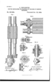
- Figure 1 is a side elevation of sufficient of a combing machine to illustrate my present invention.
- Fig. 2 is a sectional view of part of the same.
- Fig. 3 is a sectional plan view on the line 33, Fig. 2.
- Fig. 1 is a side elevation of sufficient of a combing machine to illustrate my present invention.
- Fig. 2 is a sectional view of part of the same.
- Fig. 3 is a sectional plan view on the line 33, Fig. 2.
- Fig. 1 is a side elevation of sufficient of a combing machine to illustrate my present invention.
- Fig. 3 is
- Fig. 4 is a sectional view of the drawing rollers and part of the apron used in connection therewith.
- Fig. 5 is a side view illustrating a modified planof carrying out my invention; and
- Figs. 6, 7 and 8, are views on a reduced scale, illustrating modifications of the invention.
- the shafts are mounted in bearings which are provided with adjusting devices whereby the proper pressure is imparted to the apron passing between the fluted rollers, power being applied only to the shaft A and the rotation of the fluted roller 1) being effected solely by reason of the engagement of the rollers a and b with the apron between them.
- My invention has for its object a material reduction of this expense by preventing the excessive wear of the apron, and this object I I attain by driving the fluted roller b independently of its engagement with the roller a, and in such manner that each of its teeth has aconstant tendency-to advance toward the preceding tooth of said roller a so that the pressure upon the apron due to the driving action of said roller ais removed, and the wear of the apron, therefore, very materially reduced, whereby the life of the apron is much prolonged. 7
- the two shafts A and B are connected by a pair of spur Wheels (1 andf, said spur wheel d being connected to the shaft A through the medium of an interposed elastic element having a tendency to move the wheel forward in the direction of the shafts rotation and thereby impart to the wheel f forward movement with force suffi cient to overcome the friction of the shaft B in its bearings, so that the roller 1) has a constant tendency to move in advance of the movement of the shaft.
- the power imparted to the fluted apron-carrying roller b is such as is determined by the initial tension of the spring which prevents any tight nipping of the apron between a tooth of said roller and an advancing tooth of the roller a, the tendency being to maintain the roller 6 always in such position that the advancing tooth of I the roller a will enter squarely between the teeth of said roller 1), so that the forward movement of the apron is effected IOO wheel, while its outer end is connected to the flange g of a loose collar D mounted on the shaft A and carrying a pivoted catch arm h which is adapted to engage with any one of a series of notches t' in a flanged collar F secured to the shaft A.
- said collar F therefore, rotates with the shaft, the movement of the same is transmitted to the loose collar D and through the spring g to the hub of the spur wheel at and thence through the spur wheel f and shaft B to the fluted roller 1).
- the collar D By lifting the catch arm it until it is free from the notch in the flanged collar F, the collar D can be turned on the shaft A independently of the gear, 6?, so as to adjust the initial tension of the spring g.
- the main feature of my invention might be attained without this provision for varying the initial tension of the spring.
- the collar D mightbe connected rigidly to the shaft A and the spring g relied upon to transmit the movement of the shaft to the spur wheel d, and any desired form of spring can be used or in some cases a frictional driving device can be employed in place of the elastic driver which I have just described. For instance, in Fig.
- the nuts 0 applied to a threaded portion of the shaft B serve to adjust the outer collar t and to lock the same in position after adjustment.
- the frictional connection may, however, be in the form of a peripheral band or bands 8 as shown in Fig. 6 instead of a face ringor disk, these being well known equivalents of each other.
- Figs. 1 to 3 the yielding or elastic connection is employed between the drive shaft A and its spur wheel
- Fig. 5 1 have shown the yielding connection as employed between the driven shaft B and its spur wheel.
- the wheels on and n themselves may be friction wheels as shown at m and n in Fig. 7so that the yielding driving connection is between the two shafts and not between either shaft and the wheel carried thereby, or the fric tional connection may be between the shaft A or B and its fluted roller as shown in Fig. 8.
- the shaft A is the driving shaft, but it will be evident that both shafts may be driven from a third shaft without departing from my invention.
Landscapes
- Engineering & Computer Science (AREA)
- Textile Engineering (AREA)
- Preliminary Treatment Of Fibers (AREA)
Description
(No Model.)
GQGHOLERTON. DRIVING MECHANISM FOR DRAWING OFF ROLLERS 0P GOMB'ING MAGHINES. 1
.No. 527,664. Patented Oct. 16, 1894.
FIG I.
' INVENTOR Charles C'holez-Zoiz 7 UNITED STATES PATENT QFFICE.
CHARLES OHOLERTON, oF PHILADELPHIA, PENNSYLVANIA.
DRIVING MECHANISM FOR DRAWING-OFF ROLLERS 0F COMBING-MACHINES.
SPECIFICATION forming part of Letters Patent No. 527,664, dated October 16, 1894.
Application filed December 18, 1893. Serial No. 493,916. (No model.) I
To all whom it may concern:
Improvements in Driving Mechanism for Drawing-Off Rollers of Combing-Machines, of which the following is a specification.
My invention relates to that class of drawing mechanism employed in machines for gilling, combing, or drawing fibers and comprising a pair of toothed or fluted drawing rollers with an apron passing between them, the object of my invention being to so drive said rollers as to prevent the rapid wear of the apron, which is a serious objection to mechanism of this class as at present constructed. This object I attain in the manner hereinafter set forth, reference being had to the accompanying drawings, in which Figure 1, is a side elevation of sufficient of a combing machine to illustrate my present invention. Fig. 2, is a sectional view of part of the same. Fig. 3, is a sectional plan view on the line 33, Fig. 2. Fig. 4., is a sectional view of the drawing rollers and part of the apron used in connection therewith. Fig. 5, is a side view illustrating a modified planof carrying out my invention; and Figs. 6, 7 and 8, are views on a reduced scale, illustrating modifications of the invention.
In Fig. 1 A and Brepresent two parallel shafts carrying toothed or fluted rollers a and 1) between which passes an endless belt or apronof leather or other available material which is nipped by the teeth of the rollers where they engage with each other, the construction being that usually adopted in what is known as the Noble combing machine. Usually the shafts are mounted in bearings which are provided with adjusting devices whereby the proper pressure is imparted to the apron passing between the fluted rollers, power being applied only to the shaft A and the rotation of the fluted roller 1) being effected solely by reason of the engagement of the rollers a and b with the apron between them. Those portions of the apron which receive the thrust of the teeth of the fluted roller a, are subjected to considerable pressure and consequently wear rapidly so. that the aprons soon become useless and must be discarded and replaced by new ones, the expense of these aprons being a considerable item in the cost of operating the machine.
Even if the two shafts A andB are geared together, there is always more or less driving action of one fluted roller upon the other through the medium of the interposed'apron, and as the pressure imparted to the rolls'in this class of machinery often exceedsa hundred pounds, it will be evident that rapid wear of the aprons must result, and frequent renewal of said aprons become necessary.
My invention has for its object a material reduction of this expense by preventing the excessive wear of the apron, and this object I I attain by driving the fluted roller b independently of its engagement with the roller a, and in such manner that each of its teeth has aconstant tendency-to advance toward the preceding tooth of said roller a so that the pressure upon the apron due to the driving action of said roller ais removed, and the wear of the apron, therefore, very materially reduced, whereby the life of the apron is much prolonged. 7
. As shown in Fig. 1, the two shafts A and B are connected by a pair of spur Wheels (1 andf, said spur wheel d being connected to the shaft A through the medium of an interposed elastic element having a tendency to move the wheel forward in the direction of the shafts rotation and thereby impart to the wheel f forward movement with force suffi cient to overcome the friction of the shaft B in its bearings, so that the roller 1) has a constant tendency to move in advance of the movement of the shaft. Hence the power imparted to the fluted apron-carrying roller b is such as is determined by the initial tension of the spring which prevents any tight nipping of the apron between a tooth of said roller and an advancing tooth of the roller a, the tendency being to maintain the roller 6 always in such position that the advancing tooth of I the roller a will enter squarely between the teeth of said roller 1), so that the forward movement of the apron is effected IOO wheel, while its outer end is connected to the flange g of a loose collar D mounted on the shaft A and carrying a pivoted catch arm h which is adapted to engage with any one of a series of notches t' in a flanged collar F secured to the shaft A. As said collar F, therefore, rotates with the shaft, the movement of the same is transmitted to the loose collar D and through the spring g to the hub of the spur wheel at and thence through the spur wheel f and shaft B to the fluted roller 1).
By lifting the catch arm it until it is free from the notch in the flanged collar F, the collar D can be turned on the shaft A independently of the gear, 6?, so as to adjust the initial tension of the spring g. The main feature of my invention, however, might be attained without this provision for varying the initial tension of the spring. For instance, the collar D mightbe connected rigidly to the shaft A and the spring g relied upon to transmit the movement of the shaft to the spur wheel d, and any desired form of spring can be used or in some cases a frictional driving device can be employed in place of the elastic driver which I have just described. For instance, in Fig. 5 I have shown a construction in which the shafts A and B are connected by spur wheels m and n so proportioned in respect to the diameters of the fluted rollers a and b that if the spur wheel nwas rigidly secured to the shaft B the fluted roller 1) would be driven at asomewhat higher surface speed than the roller a. The spur wheel it however is loose on the shaft B and drives the same through the medium of friction rings or washers s interposed between the hub of the wheel and collars tsuitably confined to the shaft so as to be compelled to rotate therewith, either or both of these collars being adjustable by nuts or springs or a combination of both so as to regulate the degree of friction upon the rings 5 to cause it to exceed the friction of the shaft b in its bearings.
In the present instance the nuts 0 applied to a threaded portion of the shaft B serve to adjust the outer collar t and to lock the same in position after adjustment. The frictional connection may, however, be in the form of a peripheral band or bands 8 as shown in Fig. 6 instead of a face ringor disk, these being well known equivalents of each other.
In Figs. 1 to 3 the yielding or elastic connection is employed between the drive shaft A and its spur wheel, while in Fig. 5 1 have shown the yielding connection as employed between the driven shaft B and its spur wheel. Hence it will be evident that it is immaterial with which shaft the yielding or elastic connection is employed, or in some cases the wheels on and n themselves may be friction wheels as shown at m and n in Fig. 7so that the yielding driving connection is between the two shafts and not between either shaft and the wheel carried thereby, or the fric tional connection may be between the shaft A or B and its fluted roller as shown in Fig. 8. As shown in the drawings, the shaft A is the driving shaft, but it will be evident that both shafts may be driven from a third shaft without departing from my invention.
Having thus described my invention, I claim and desire to secure by Letters Patcut-- 1. The combination in a machine for gilling or combing fibers, of the fluted drawing rollers and apron, with roller driving mechanism having a yielding connection between the driving and driven roller, whereby the friction of said driven roller in its bearings is overcome, and said roller has a constant advancing tendency, substantially as specified.
2. The combination in a machine for gilling or combing fibers, of the fluted rollers and apron, the shafts of said rollers, and driving mechanism for said shafts having as one of its elements a yielding connection between one of the shafts and a wheel thereon, whereby the friction of the driven shaft in its bearings is overcome, and a constant advancing tendency is imparted thereto, substantially as specified.
3. The combination in a machine for gilling or combing fibers, of the fluted drawing rollers and apron, the shafts of said rollers, gearing connecting said shafts, a yielding connection between one of said shafts and a wheel thereon, and means for regulating the tension of said yielding connection, whereby the friction of the driven shaft in its bearings will be overcome, and a constant advancing tendency will be imparted to said shaft, substantially as specified.
4. The combination in a machine for gilling or combing fibers, of the fluted drawing rollers and apron, the shafts of said rollers, gear Wheels connecting said shafts, a collar on one of said shafts, a spring interposed between said collar and the gear wheel of said shaft, and serving as a means of connecting CHARLES OHOLERTON.
Witnesses:
WILLIAM A. BARR, JOSEPH IL'KLEIN.
Publications (1)
| Publication Number | Publication Date |
|---|---|
| US527664A true US527664A (en) | 1894-10-16 |
Family
ID=2596453
Family Applications (1)
| Application Number | Title | Priority Date | Filing Date |
|---|---|---|---|
| US527664D Expired - Lifetime US527664A (en) | Driving mechanism for drawing-off rollers of combing-machines |
Country Status (1)
| Country | Link |
|---|---|
| US (1) | US527664A (en) |
-
0
- US US527664D patent/US527664A/en not_active Expired - Lifetime
Similar Documents
| Publication | Publication Date | Title |
|---|---|---|
| US527664A (en) | Driving mechanism for drawing-off rollers of combing-machines | |
| US521677A (en) | Island | |
| US510694A (en) | Belt starting and stopping mechanism | |
| US1220304A (en) | Belt-gearing attachment for roller-shafts. | |
| US1255912A (en) | Machine for wearing in drive-chains. | |
| US473254A (en) | Grip-pulley | |
| US331239A (en) | Rope-driving machinery | |
| US340061A (en) | Geoege l | |
| US818450A (en) | Variable-speed counter-shaft mechanism. | |
| US276104A (en) | weg-mann | |
| US357239A (en) | Tread-power governor | |
| US609809A (en) | Third to john charles howell | |
| US170577A (en) | Improvement in band sawing-machines | |
| US398274A (en) | Benjamin ormerod and george iiawortii | |
| US310127A (en) | Roller-mill | |
| US335460A (en) | Automatic speed-regulator | |
| US697311A (en) | Drive mechanism for crushing-rolls. | |
| US889514A (en) | Gearing. | |
| US941183A (en) | Tension-regulating device for spindle-bands. | |
| US526275A (en) | watson | |
| US540382A (en) | elliott | |
| US403109A (en) | Feed device for wire-weaving machines | |
| US260532A (en) | Friction-gearing for roller-m ills | |
| US117010A (en) | Improvement in friction-pulleys | |
| US1126858A (en) | Feed mechanism for carding-engines. |