US5276406A - Low noise wide dynamic range amplifiers - Google Patents
Low noise wide dynamic range amplifiers Download PDFInfo
- Publication number
- US5276406A US5276406A US07/837,345 US83734592A US5276406A US 5276406 A US5276406 A US 5276406A US 83734592 A US83734592 A US 83734592A US 5276406 A US5276406 A US 5276406A
- Authority
- US
- United States
- Prior art keywords
- amplifier
- input
- gaas fet
- impedance matching
- output
- Prior art date
- Legal status (The legal status is an assumption and is not a legal conclusion. Google has not performed a legal analysis and makes no representation as to the accuracy of the status listed.)
- Expired - Fee Related
Links
- 229910001218 Gallium arsenide Inorganic materials 0.000 claims abstract description 22
- 229920006395 saturated elastomer Polymers 0.000 claims description 3
- 230000002452 interceptive effect Effects 0.000 abstract description 2
- 239000003990 capacitor Substances 0.000 description 13
- 238000010586 diagram Methods 0.000 description 9
- 230000000903 blocking effect Effects 0.000 description 5
- 230000005540 biological transmission Effects 0.000 description 2
- 230000005457 Black-body radiation Effects 0.000 description 1
- 230000005672 electromagnetic field Effects 0.000 description 1
- 230000007613 environmental effect Effects 0.000 description 1
- 230000005669 field effect Effects 0.000 description 1
- 238000004519 manufacturing process Methods 0.000 description 1
- 239000011159 matrix material Substances 0.000 description 1
- 238000000034 method Methods 0.000 description 1
- 238000012986 modification Methods 0.000 description 1
- 230000004048 modification Effects 0.000 description 1
- 238000012545 processing Methods 0.000 description 1
- 238000012552 review Methods 0.000 description 1
- 239000004065 semiconductor Substances 0.000 description 1
- 239000007787 solid Substances 0.000 description 1
Images
Classifications
-
- H—ELECTRICITY
- H03—ELECTRONIC CIRCUITRY
- H03F—AMPLIFIERS
- H03F3/00—Amplifiers with only discharge tubes or only semiconductor devices as amplifying elements
- H03F3/189—High-frequency amplifiers, e.g. radio frequency amplifiers
- H03F3/19—High-frequency amplifiers, e.g. radio frequency amplifiers with semiconductor devices only
- H03F3/193—High-frequency amplifiers, e.g. radio frequency amplifiers with semiconductor devices only with field-effect devices
- H03F3/1935—High-frequency amplifiers, e.g. radio frequency amplifiers with semiconductor devices only with field-effect devices with junction-FET devices
Definitions
- This invention relates to low noise wide dynamic range electronic amplifiers.
- Low noise wide dynamic range amplifiers are used where a desired signal must be detected and amplified in the presence of spurious noise signals.
- GaAs FET transistors are low noise semiconductor devices and have been employed in low noise, low power amplifiers.
- Bipolar transistors have also been used in medium and high power amplifiers but these bipolar transistors are not used where low noise performance is required; hence, only low power amplifiers are known in the prior art for low noise applications.
- Noise is a broadband electromagnetic field, generated by various environmental effects and artificial devices. Noise can be categorized as either natural or man-made. Natural noise may be either thermal or electrical in origin. All objects radiate noise as a result of their thermal energy content. This is known a black-body radiation.
- Electromagnetic noise is produced by many different man-made devices. In general, any circuit or appliance that produces electric arcing will produce noise.
- the level of electromagnetic noise affects the ease with which radio frequency communications can be carried out.
- the higher the noise level the stronger a signal must be if it is to be received.
- the signal-to-noise ratio can be maximized in a variety of ways.
- the narrower the bandwidth of the transmitted signal, and the narrower the passband of the receiver the better the signal-to-noise ratio at a given frequency. This improvement occurs, however, at the expense of data transmission speed capability. Circuits such as noise blankers and limiters are sometimes helpful in improving the signal-to-noise ratio.
- Noise reducing antennas can also be used to advantage in some cases. There is a limit to how much the noise level can be reduced; a certain amount of noise always exists.
- This invention is a high power electronic amplifier which has excellent low noise performance which is commensurate with the prior art low noise, low power amplifiers.
- This low level bias condition results in low power handling capability (approximately +5 to +1-dBm for the bias point range specified).
- One method to improve the low power performance is to parallel a number of such stages thereby splitting the incoming signal to be processed by each cell of the parallel combination. The separately amplified signals are then recombined at the output port of the paralleled transistors. The invention employs such combining to prove that the power handling capability increases by approximately 3 dB each time the number of cells is doubled while the intrinsic noise figure of the combination remains essentially constant.
- Paralleling devices has limitations due to differences in processing parameters during fabrication. Discrete device parameters such as g m , V p , I dss , etc., can vary as much as ⁇ 30% from the typical values.
- each of the cells should be as identical as possible. This can be accomplished by fabricating the parallel configuration in a single chip. Such devices have been fabricated and already exist as commercially available transistors which were designed and intended for use as power amplifiers rather than in low noise applications. The manufacturers do not list noise figure in the specification sheets for such transistors and one would not expect large signal devices to display good low noise performance.
- the wide dynamic range performance can be achieved in an amplifier using power GaAs FET devices by incorporating them in any one of the circuit configurations described herein to achieve simultaneously, a low noise figure, higher input/output intercept performance, higher output power, and improved ruggedness toward high input interfering signals, while not sacrificing other desirable terminal characteristics, (i.e. gain, VSWR, etc.).
- a principal object of our invention is the provision of a low noise wide dynamic range amplifier.
- Another object and advantage of our invention is the provision of high power amplifiers which have excellent low noise performance.
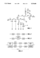
- FIG. 1 is a schematic diagram of the circuit of the invention
- FIG. 3 is a block diagram of a feedback circuit using the schematic of FIG. 1 in another embodiment of the invention.
- FIG. 4 is a block diagram of a multipath circuit employing the schematic of FIG. 1
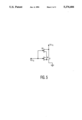
- FIG. 5 is a schematic diagram of the circuit of FIG. 1. with active feedback elements.
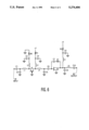
- FIG. 6 is a schematic diagram of a circuit which may be employed having an active input impedance matching element.
- FIG. 1 is a schematic diagram of one embodiment of the invention employing a GaAs FET, Q1, connected in the configuration shown in FIG. 3.
- the RF input terminal is coupled to the gate of transistor Q1 via capacitors C1, C2, C3 and inductors L1 and L3.
- Capacitor C1 serves as a DC blocking capacitor and also provides some impedance matching at low frequencies.
- Inductor L1 together with capacitors C2 and C3 act as a low pass impedance matching circuit.
- Inductor L2 can serve as either an RF choke, or an impedance matching element depending on the frequency, and/or the bandwidth requirements.
- connection node "P" at the junction of L1, L3 and C3 also is fed by a voltage divider comprised of resistors R1 and R2 to set the gate to source voltage and thus, the DC operating point of Q1. All inductors may be lumped or distributed depending on the operating frequency range and serve to adjust the gain slope of Q1 and provide for impedance matching.
- a feedback network comprised of capacitor C5, resistor Rf, and inductor L5 is connected between node "P" and the junction of inductor L4, L6 and L7.
- Capacitor C5 is a large value DC blocking capacitor. Resistor Rf and inductor L5 serve to adjust the gain and terminal impedance of the amplifier. In the RF output portion of the circuit, inductor L6 and capacitor C6 serve as a low pass output matching circuit.
- AC bypass capacitors C4, C9, C7 and C8 are selected in the usual manner.
- Capacitor C10 is typically selected as a DC blocking capacitor, but can serve as an impedance matching element as well. Resistor R3 sets the DC operating voltage of Q1.
- FIG. 2 shows a single stage implementation.
- FIG. 3 is a feedback network and
- FIG. 4 is a multi-path network.
- IMN input matching network
- OMN output matching network
- FET GaAs FET device
- FBN feedback network. Examples of such combinations are cascade connection, parallel connection in (N ⁇ M) matrix connections.
- Input and output matching networks IMN and OMN refer to any combination of passive elements (resistors, capacitors, inductors, transformers, transmission line couplers, etc.), or active elements (transistors).
- Feedback networks can be any combination of circuit elements similar to the aforementioned input matching networks or output matching networks.
- connection points of any feedback networks is considered arbitrary and optional; however, in certain applications, such as those shown in FIGS. 1-3, feedback networks are required as a significant part of the circuit scheme needed to realize the full advantage of the invention.
- the N-way signal splitting and combining networks in FIG. 4 is any combination of passive circuit elements which provide the signal splitting and combining function.
- FIG. 5 is a schematic diagram of the circuit of FIG. 1 with active feedback elements in the circuit.
- a second transistor Q2 is connected in the feedback loop across Q1.
- FIG. 6 is a schematic diagram of a circuit which may be employed having an active input impedance matching element. The following table described the circuit elements of FIG. 5:
- the upper ranges for the GaAs FET devices set forth above are not limiting but may increase by 50% from the values in the table above.
Landscapes
- Engineering & Computer Science (AREA)
- Power Engineering (AREA)
- Amplifiers (AREA)
Abstract
Certain GaAs FET devices are employed to accomplish low noise performance and simultaneous high power handling capability, i.e. high dynamic range performance, in an amplifier using larger GaAs FET devices. Such devices are incorporated in different circuit configurations to achieve amplifiers having, simultaneously, a low noise figure, higher input/output intercept performance, higher output power, and improved ruggedness toward high input interfering signals, while not sacrificing other highly desirable terminal characteristics, (i.e. gain, VSWR, etc.).
Description
This invention relates to low noise wide dynamic range electronic amplifiers.
Low noise wide dynamic range amplifiers are used where a desired signal must be detected and amplified in the presence of spurious noise signals. GaAs FET transistors are low noise semiconductor devices and have been employed in low noise, low power amplifiers. Bipolar transistors have also been used in medium and high power amplifiers but these bipolar transistors are not used where low noise performance is required; hence, only low power amplifiers are known in the prior art for low noise applications.
Noise is a broadband electromagnetic field, generated by various environmental effects and artificial devices. Noise can be categorized as either natural or man-made. Natural noise may be either thermal or electrical in origin. All objects radiate noise as a result of their thermal energy content. This is known a black-body radiation.
Electromagnetic noise is produced by many different man-made devices. In general, any circuit or appliance that produces electric arcing will produce noise.
The level of electromagnetic noise affects the ease with which radio frequency communications can be carried out. The higher the noise level, the stronger a signal must be if it is to be received. The signal-to-noise ratio can be maximized in a variety of ways. The narrower the bandwidth of the transmitted signal, and the narrower the passband of the receiver, the better the signal-to-noise ratio at a given frequency. This improvement occurs, however, at the expense of data transmission speed capability. Circuits such as noise blankers and limiters are sometimes helpful in improving the signal-to-noise ratio. Noise reducing antennas can also be used to advantage in some cases. There is a limit to how much the noise level can be reduced; a certain amount of noise always exists.
This invention is a high power electronic amplifier which has excellent low noise performance which is commensurate with the prior art low noise, low power amplifiers.
Many electronic systems such as radar communications receivers require the capability to receive low level signals in the presence of large spurious signals. Most modern low noise solid state receivers operating in the frequency ranges of VHF through microwave employ GaAs field effect transistors as the input stages of the amplifier chain. These transistors are designed with very fine line geometries which improve the high frequency performance and enhance the inherent low noise characteristics of such devices. An attendant characteristic of GaAs FET (MESFET) designed in this way is that the power handling capability is relatively small. Typical state of the art low noise MESFETs with 0.3 to 0.5 micron gate widths provide low noise operation when biased for a drain current, Ids, in the 5 to 15 mA range and a drain to source voltage, VDS, of 2-4 volts. This low level bias condition results in low power handling capability (approximately +5 to +1-dBm for the bias point range specified). One method to improve the low power performance is to parallel a number of such stages thereby splitting the incoming signal to be processed by each cell of the parallel combination. The separately amplified signals are then recombined at the output port of the paralleled transistors. The invention employs such combining to prove that the power handling capability increases by approximately 3 dB each time the number of cells is doubled while the intrinsic noise figure of the combination remains essentially constant. Paralleling devices has limitations due to differences in processing parameters during fabrication. Discrete device parameters such as gm, Vp, Idss, etc., can vary as much as ±30% from the typical values. These differences cause the bias conditions as well as the RF performance of the various cells of the parallel combination to vary. For optimum performance, each of the cells should be as identical as possible. This can be accomplished by fabricating the parallel configuration in a single chip. Such devices have been fabricated and already exist as commercially available transistors which were designed and intended for use as power amplifiers rather than in low noise applications. The manufacturers do not list noise figure in the specification sheets for such transistors and one would not expect large signal devices to display good low noise performance.
These devices are employed to accomplish low noise performance and simultaneous high power handling capability, i.e. high dynamic range performance. The wide dynamic range performance can be achieved in an amplifier using power GaAs FET devices by incorporating them in any one of the circuit configurations described herein to achieve simultaneously, a low noise figure, higher input/output intercept performance, higher output power, and improved ruggedness toward high input interfering signals, while not sacrificing other desirable terminal characteristics, (i.e. gain, VSWR, etc.).
A principal object of our invention is the provision of a low noise wide dynamic range amplifier. Another object and advantage of our invention is the provision of high power amplifiers which have excellent low noise performance.
These as well as further objects and advantages of the invention will become apparent to those skilled in the art from a review of the following detailed specification reference being made to the accompanying drawings in which:
FIG. 1 is a schematic diagram of the circuit of the invention;
FIG. 2 is a block diagram of a single stage configuration using the circuit of FIG. 1 according to the invention, with the value of Rf =∞;
FIG. 3 is a block diagram of a feedback circuit using the schematic of FIG. 1 in another embodiment of the invention; and
FIG. 4 is a block diagram of a multipath circuit employing the schematic of FIG. 1
FIG. 5 is a schematic diagram of the circuit of FIG. 1. with active feedback elements.
FIG. 6 is a schematic diagram of a circuit which may be employed having an active input impedance matching element.
FIG. 1 is a schematic diagram of one embodiment of the invention employing a GaAs FET, Q1, connected in the configuration shown in FIG. 3. The RF input terminal is coupled to the gate of transistor Q1 via capacitors C1, C2, C3 and inductors L1 and L3. Capacitor C1 serves as a DC blocking capacitor and also provides some impedance matching at low frequencies. Inductor L1 together with capacitors C2 and C3 act as a low pass impedance matching circuit. Inductor L2 can serve as either an RF choke, or an impedance matching element depending on the frequency, and/or the bandwidth requirements.
The connection node "P", at the junction of L1, L3 and C3 also is fed by a voltage divider comprised of resistors R1 and R2 to set the gate to source voltage and thus, the DC operating point of Q1. All inductors may be lumped or distributed depending on the operating frequency range and serve to adjust the gain slope of Q1 and provide for impedance matching.
A feedback network comprised of capacitor C5, resistor Rf, and inductor L5 is connected between node "P" and the junction of inductor L4, L6 and L7. Capacitor C5 is a large value DC blocking capacitor. Resistor Rf and inductor L5 serve to adjust the gain and terminal impedance of the amplifier. In the RF output portion of the circuit, inductor L6 and capacitor C6 serve as a low pass output matching circuit. AC bypass capacitors C4, C9, C7 and C8 are selected in the usual manner. Capacitor C10 is typically selected as a DC blocking capacitor, but can serve as an impedance matching element as well. Resistor R3 sets the DC operating voltage of Q1.
Additional circuit configurations are provided in other embodiments of the invention shown in FIGS. 2-4. FIG. 2 shows a single stage implementation. FIG. 3 is a feedback network and FIG. 4 is a multi-path network. In FIGS. 2-4. IMN=input matching network; OMN=output matching network; FET=GaAs FET device; and FBN=feedback network. Examples of such combinations are cascade connection, parallel connection in (N×M) matrix connections. Input and output matching networks IMN and OMN refer to any combination of passive elements (resistors, capacitors, inductors, transformers, transmission line couplers, etc.), or active elements (transistors). Feedback networks can be any combination of circuit elements similar to the aforementioned input matching networks or output matching networks. Location of the connection points of any feedback networks is considered arbitrary and optional; however, in certain applications, such as those shown in FIGS. 1-3, feedback networks are required as a significant part of the circuit scheme needed to realize the full advantage of the invention. The N-way signal splitting and combining networks in FIG. 4 is any combination of passive circuit elements which provide the signal splitting and combining function.
FIG. 5 is a schematic diagram of the circuit of FIG. 1 with active feedback elements in the circuit. In FIG. 5, a second transistor Q2 is connected in the feedback loop across Q1.
FIG. 6 is a schematic diagram of a circuit which may be employed having an active input impedance matching element. The following table described the circuit elements of FIG. 5:
______________________________________
ELEMENT    FUNCTION
______________________________________
C1         DC BLOCKING CAPACITOR
C6         "
C7         "
 C10       "
L1         INPUT MATCHING
C2         "
L4         INTER STAGE MATCHING
C5         "
C8         OUTPUT MATCHING
L6         "
L2         RF BLOCKING CHOKE
L3         "
L5         "
C3         RF BYPASS
C4         "
C9         "
RB         SOURCE SELF-BIAS RESISTOR
R1         DRAIN BIAS RESISTOR (Q1)
RF         Q2 FEEDBACK RESISTOR
R2         DRAIN BIAS RESISTOR (Q2)
Q1         ACTIVE INPUT IMPEDANCE
           TRANSFORMER
Q2         GaAs FET amplifier akin to Q1 of FIG. 1
______________________________________
The following are examples of circuits constructed in accordance with our invention:
______________________________________
       EXAMPLES
       1         2           3
______________________________________
C1       0           100 pf      1000 pf 470 pf
C2       2 pf        0           6.8 pf
C3       0           0           0
C4       100 pf      .01 uf      1000 pf
C5       10 pf       .10 uf      1000 pf
C6       0           0           1 pf
C7       100 pf      .01 uf      1000 pf
C8       .1 uf       .1 uf       .1 uf
C9       .01 uf      .1 uf       .1 uf
C10      100 pf      1000 pf     33 pf
L1       0           8 nH        18 nH
L2       5 nH        10K ohms    25 nH
L3       P.L.        P.L.        P.L.
         .2" L × .1" W
                     .3" L × .1" W
                                 .2" L × .1" W
L4       0           P.L.        P.L.
                     .2" L × .1" W
                                 .2" L × .1" W
L5       22 nH       24 nH       22 nH
L6       3 nH        1:2 transformer
                                 1:4 transformer
L7       3.5 nH      .22 uH      18 nH
R1       10K ohms    10K ohms    10k ohms
R2       select @ test
                     select @ test
                                 select @ test
Rf       10K ohms    330 ohms    750 ohms
R3       20 ohms     6.5 ohms    13 ohms
-Vg      -5V         -5V         -5V
+V       12 V        12 V        12 V
ELECTRICAL PERFORMANCE ACHIEVED
Freq.    1025-1150 MHz
                     60-100 MHz  400-625 MHz
Gain     15 dB       16 dB       17 dB
Noise    1.9 dB      2.0 dB      1.7 dB
Figure
VSWR     2.0:1 in/out
                     1.5:1/1.7:1 2.0:1 in/out
(in/out)             in/out
Pwr. Output
         +24 dBm     +28 dBm     +29 dBm
3rd Order
Intercept
         +36 dBm     +40 dBm     +41 dBm
Point
______________________________________
Typical characteristics of GaAs FET devices used in the above examples are:
______________________________________
Max. drain - source voltage (Vds)
                      12-17     V
max. power dissipation (watts @25° C.)
                      4-8       W
Saturated drain current (Idss)
                      .25       minimum
Max. gate-source voltage (Vgs)
                      -5        V
Transconductance (gm) 120-350   mS
Pinch-off voltage     -1 to -5  V
______________________________________
The upper ranges for the GaAs FET devices set forth above are not limiting but may increase by 50% from the values in the table above.
As modifications to the invention may be made without departing from the spirit and scope of our invention, what is sought to be protected is set forth in the appended claims.
Claims (7)
1. An electronic amplifier having low noise performance and simultaneous high power handling capability comprising: an input terminal and an output terminal, input impedance matching means connected to said input terminal for matching the impedance at said terminal to said amplifier; a GaAs FET transistor device connected to said input impedance matching means for amplifying the signal at said input terminal, and output impedance matching means connected to said GaAs FET transistor device and to said output terminal for matching the impedance at said output terminal to said GaAs FET transistor device; said GaAs FET transistor device having the following characteristics:
______________________________________
Max. drain - source voltage (Vds)
                      12-17     V
max. power dissipation (watts @25° C.)
                      4-8       W
Saturated drain current (Idss)
                      .25       minimum
Max. gate-source voltage (Vgs)
                      -5        V
Transconductance (gm) 120-350   mS
Pinch-off voltage     -1 to -5  V
______________________________________
where the upper value of each of said characteristics having an upper value may vary by an amount between 0% and 50% of said upper value; and said input impedance matching means and said output impedance matching means each including an active circuit element.
2. The amplifier of claim 1 further including feedback network means connected across said GaAs FET transistor device for adjusting the gain and impedance level of said GaAs FET transistor device.
3. The amplifier of claim 1 wherein said input impedance matching means and said output impedance matching means includes passive circuit elements.
4. The amplifier of claim 2 wherein said feedback network means includes passive circuit elements.
5. The amplifier of claim 2 wherein said feedback network means includes active circuit elements.
6. An electronic amplifier circuit having low noise performance and simultaneous high power handling capability comprising: an input terminal and an output terminal, input signal splitting means connected to said input terminal for splitting said input signal into a plurality of signals; input impedance matching means connected to said input signal splitting means for each of said plurality of signals for matching the impedance at said input signal splitting means to a GaAs FET amplifier means; GaAs FET amplifier means connected to each of said input impedance matching means for amplifying the signal at said input impedance matching means, output impedance matching means connected to each of said GaAs FET amplifier means for matching the impedance at each of said GaAs FET amplifier means to an output signal combining means; output signal combining means connected to each of said output impedance matching means and to said output terminal for recombining said signal; said GaAs FET amplifier means having the following characteristics:
______________________________________
Max. drain - source voltage (Vds)
                      12-17     V
max. power dissipation (watts @25° C.)
                      4-8       W
Saturated drain current (Idss)
                      .25       minimum
Max. gate-source voltage (Vgs)
                      -5        V
Transconductance (gm) 120-350   mS
Pinch-off voltage     -1 to -5  V.
______________________________________
7. The amplifier of claim 6 wherein said input signal splitting means and said output signal combining means include passive circuit elements.
Priority Applications (2)
| Application Number | Priority Date | Filing Date | Title |
|---|---|---|---|
| US07/837,345 US5276406A (en) | 1992-02-13 | 1992-02-13 | Low noise wide dynamic range amplifiers |
| PCT/US1993/001279 WO1993016525A1 (en) | 1992-02-13 | 1993-02-12 | Low noise wide dynamic range amplifiers |
Applications Claiming Priority (1)
| Application Number | Priority Date | Filing Date | Title |
|---|---|---|---|
| US07/837,345 US5276406A (en) | 1992-02-13 | 1992-02-13 | Low noise wide dynamic range amplifiers |
Publications (1)
| Publication Number | Publication Date |
|---|---|
| US5276406A true US5276406A (en) | 1994-01-04 |
Family
ID=25274201
Family Applications (1)
| Application Number | Title | Priority Date | Filing Date |
|---|---|---|---|
| US07/837,345 Expired - Fee Related US5276406A (en) | 1992-02-13 | 1992-02-13 | Low noise wide dynamic range amplifiers |
Country Status (2)
| Country | Link |
|---|---|
| US (1) | US5276406A (en) |
| WO (1) | WO1993016525A1 (en) |
Cited By (27)
| Publication number | Priority date | Publication date | Assignee | Title |
|---|---|---|---|---|
| US5483191A (en) * | 1994-09-23 | 1996-01-09 | At&T Corp. | Apparatus for biasing a FET with a single voltage supply |
| US5736901A (en) * | 1995-04-04 | 1998-04-07 | Matsushita Electric Industrial Co., Ltd. | Radio frequency amplifier with stable operation and restrained oscillation at low frequencies |
| US5999058A (en) * | 1997-02-21 | 1999-12-07 | Nec Corporation | Microwave amplifier |
| US6204728B1 (en) | 1999-01-28 | 2001-03-20 | Maxim Integrated Products, Inc. | Radio frequency amplifier with reduced intermodulation distortion |
| US6249186B1 (en) * | 1998-04-10 | 2001-06-19 | Taiyo Yuden Co., Ltd. | High-frequency power amplifier circuit and high-frequency power amplifier module |
| US6496065B1 (en) * | 2000-10-31 | 2002-12-17 | Pohang University Of Science And Technology Foundation | Linear amplifier using frequency 2nd order intermodulation feed-forwarding method |
| US6566962B2 (en) * | 2001-05-01 | 2003-05-20 | Koninklijke Philips Electronics N.V. | Apparatus and method for tuning an inter-stage matching network of an integrated multistage amplifier |
| US6670850B1 (en) * | 2002-06-13 | 2003-12-30 | Linear Technology Corp. | Ultra-wideband constant gain CMOS amplifier |
| US20040012444A1 (en) * | 2000-11-24 | 2004-01-22 | Jaspal Bharj | Lineariser |
| US6750711B2 (en) * | 2001-04-13 | 2004-06-15 | Eni Technology, Inc. | RF power amplifier stability |
| US20040201422A1 (en) * | 2002-09-06 | 2004-10-14 | Martin Goss | Power amplifier system |
| US20050083134A1 (en) * | 2003-10-20 | 2005-04-21 | Kapoor Samay P. | Amplifier circuit |
| US20050253656A1 (en) * | 2002-05-22 | 2005-11-17 | Niels Kramer | Rf power amplifier |
| US7176769B1 (en) * | 2004-11-29 | 2007-02-13 | Hrl Laboratories, Llc | Harmonic termination circuit for medium bandwidth microwave power amplifiers |
| US7215221B1 (en) * | 2004-08-30 | 2007-05-08 | Hrl Laboratories, Llc | Harmonic termination circuit for medium bandwidth microwave power amplifiers |
| US20100253319A1 (en) * | 2009-03-20 | 2010-10-07 | Cehelnik Thomas G | E-field sensor arrays for interactive gaming, computer interfaces, machine vision, medical imaging, and geological exploration CIP |
| US20120037969A1 (en) * | 2010-08-12 | 2012-02-16 | Freescale Semiconductor, Inc. | Monolithic microwave integrated circuit |
| US20130335146A1 (en) * | 2011-03-16 | 2013-12-19 | Sony Corporation | Gain control circuit, communication device, electronic appliance, and gain control method |
| US8723602B2 (en) * | 2012-08-10 | 2014-05-13 | Tensorcom, Inc. | Method and apparatus for a class-E load tuned beamforming 60 GHz transmitter |
| US8873339B2 (en) | 2012-08-10 | 2014-10-28 | Tensorcom, Inc. | Method and apparatus for a clock and signal distribution network for a 60 GHz transmitter system |
| US20160344353A1 (en) * | 2015-05-22 | 2016-11-24 | Freescale Semiconductor, Inc. | Rf amplifier output circuit device with integrated current path, and methods of manufacture thereof |
| US20170366141A1 (en) * | 2010-04-22 | 2017-12-21 | Nxp Usa, Inc. | Rf power transistor circuits |
| US10270402B1 (en) * | 2017-11-30 | 2019-04-23 | Nxp Usa, Inc. | Broadband input matching and video bandwidth circuits for power amplifiers |
| US10742174B2 (en) | 2018-12-21 | 2020-08-11 | Nxp Usa, Inc. | Broadband power transistor devices and amplifiers with input-side harmonic termination circuits and methods of manufacture |
| US20220029591A1 (en) * | 2019-03-25 | 2022-01-27 | Mitsubishi Electric Corporation | High frequency semiconductor amplifier |
| US11736074B2 (en) * | 2019-08-08 | 2023-08-22 | The Regents Of The University Of California | Noise reduction in high frequency amplifiers using transmission lines to provide feedback |
| US12231091B1 (en) * | 2020-05-15 | 2025-02-18 | AmpliTech, Inc. | Multiple transistor LNA MMIC design |
Citations (2)
| Publication number | Priority date | Publication date | Assignee | Title |
|---|---|---|---|---|
| US4803443A (en) * | 1987-04-10 | 1989-02-07 | Mitsubishi Denki Kabushiki Kaisha | Microwave power combining FET amplifier |
| US5015968A (en) * | 1990-07-27 | 1991-05-14 | Pacific Monolithics | Feedback cascode amplifier |
-
1992
- 1992-02-13 US US07/837,345 patent/US5276406A/en not_active Expired - Fee Related
-
1993
- 1993-02-12 WO PCT/US1993/001279 patent/WO1993016525A1/en not_active Ceased
Patent Citations (2)
| Publication number | Priority date | Publication date | Assignee | Title |
|---|---|---|---|---|
| US4803443A (en) * | 1987-04-10 | 1989-02-07 | Mitsubishi Denki Kabushiki Kaisha | Microwave power combining FET amplifier |
| US5015968A (en) * | 1990-07-27 | 1991-05-14 | Pacific Monolithics | Feedback cascode amplifier |
Cited By (51)
| Publication number | Priority date | Publication date | Assignee | Title |
|---|---|---|---|---|
| US5483191A (en) * | 1994-09-23 | 1996-01-09 | At&T Corp. | Apparatus for biasing a FET with a single voltage supply |
| US5646570A (en) * | 1994-09-23 | 1997-07-08 | Lucent Technologies Inc. | Apparatus for biasing a field effect transistor with a single voltage supply |
| US5736901A (en) * | 1995-04-04 | 1998-04-07 | Matsushita Electric Industrial Co., Ltd. | Radio frequency amplifier with stable operation and restrained oscillation at low frequencies |
| US5999058A (en) * | 1997-02-21 | 1999-12-07 | Nec Corporation | Microwave amplifier |
| US6249186B1 (en) * | 1998-04-10 | 2001-06-19 | Taiyo Yuden Co., Ltd. | High-frequency power amplifier circuit and high-frequency power amplifier module |
| US6204728B1 (en) | 1999-01-28 | 2001-03-20 | Maxim Integrated Products, Inc. | Radio frequency amplifier with reduced intermodulation distortion |
| US6496065B1 (en) * | 2000-10-31 | 2002-12-17 | Pohang University Of Science And Technology Foundation | Linear amplifier using frequency 2nd order intermodulation feed-forwarding method |
| US20040012444A1 (en) * | 2000-11-24 | 2004-01-22 | Jaspal Bharj | Lineariser |
| US7057464B2 (en) * | 2000-11-24 | 2006-06-06 | Nokia Corporation | Lineariser |
| US6750711B2 (en) * | 2001-04-13 | 2004-06-15 | Eni Technology, Inc. | RF power amplifier stability |
| WO2002089319A3 (en) * | 2001-05-01 | 2004-01-15 | Koninkl Philips Electronics Nv | Apparatus and method for tuning an inter-stage matching network of an integrated multistage amplifier |
| US6566962B2 (en) * | 2001-05-01 | 2003-05-20 | Koninklijke Philips Electronics N.V. | Apparatus and method for tuning an inter-stage matching network of an integrated multistage amplifier |
| US20050253656A1 (en) * | 2002-05-22 | 2005-11-17 | Niels Kramer | Rf power amplifier |
| US7154339B2 (en) * | 2002-05-22 | 2006-12-26 | Nxp B.V. | RF power amplifier |
| US6946914B1 (en) | 2002-06-13 | 2005-09-20 | Linear Technology Corporation | Ultra-wideband constant gain CMOS amplifier |
| US20050248408A1 (en) * | 2002-06-13 | 2005-11-10 | Linear Technology Corporation | Ultra-wideband constant gain CMOS amplifier |
| US6670850B1 (en) * | 2002-06-13 | 2003-12-30 | Linear Technology Corp. | Ultra-wideband constant gain CMOS amplifier |
| US7202748B2 (en) | 2002-06-13 | 2007-04-10 | Linear Technology Corporation | Ultra-wideband constant gain CMOS amplifier |
| US7339437B2 (en) | 2002-06-13 | 2008-03-04 | Linear Technology Corp. | Ultra-wideband constant gain CMOS amplifier |
| US20070188240A1 (en) * | 2002-06-13 | 2007-08-16 | Linear Technology Corporation | Ultra-wideband constant gain cmos amplifier |
| US7123097B2 (en) | 2002-06-13 | 2006-10-17 | Linear Technology Corporation | Ultra-wideband constant gain CMOS amplifier |
| US20070001769A1 (en) * | 2002-06-13 | 2007-01-04 | Roach Steven D | Ultra-wideband constant gain cmos amplifier |
| US20040201422A1 (en) * | 2002-09-06 | 2004-10-14 | Martin Goss | Power amplifier system |
| US7042294B2 (en) * | 2002-09-06 | 2006-05-09 | Nokia Corporation | Power amplifier system |
| US7038547B2 (en) * | 2003-10-20 | 2006-05-02 | Freescale Semiconductor, Inc. | Amplifier circuit |
| US20050083134A1 (en) * | 2003-10-20 | 2005-04-21 | Kapoor Samay P. | Amplifier circuit |
| US7215221B1 (en) * | 2004-08-30 | 2007-05-08 | Hrl Laboratories, Llc | Harmonic termination circuit for medium bandwidth microwave power amplifiers |
| US7176769B1 (en) * | 2004-11-29 | 2007-02-13 | Hrl Laboratories, Llc | Harmonic termination circuit for medium bandwidth microwave power amplifiers |
| US8810249B2 (en) * | 2009-03-20 | 2014-08-19 | Thomas G. Cehelnik | E-field sensor arrays for interactive gaming, computer interfaces, machine vision, medical imaging, and geological exploration CIP |
| US20100253319A1 (en) * | 2009-03-20 | 2010-10-07 | Cehelnik Thomas G | E-field sensor arrays for interactive gaming, computer interfaces, machine vision, medical imaging, and geological exploration CIP |
| US10199991B2 (en) | 2010-04-22 | 2019-02-05 | Nxp Usa, Inc. | RF power transistor circuits |
| US10771019B2 (en) | 2010-04-22 | 2020-09-08 | Nxp Usa, Inc. | RF power transistor circuits |
| US10153738B2 (en) * | 2010-04-22 | 2018-12-11 | Nxp Usa, Inc. | RF power transistor circuits |
| US20170366141A1 (en) * | 2010-04-22 | 2017-12-21 | Nxp Usa, Inc. | Rf power transistor circuits |
| US20120037969A1 (en) * | 2010-08-12 | 2012-02-16 | Freescale Semiconductor, Inc. | Monolithic microwave integrated circuit |
| US9064712B2 (en) * | 2010-08-12 | 2015-06-23 | Freescale Semiconductor Inc. | Monolithic microwave integrated circuit |
| US9871008B2 (en) | 2010-08-12 | 2018-01-16 | Nxp Usa, Inc. | Monolithic microwave integrated circuits |
| US9508599B2 (en) | 2010-08-12 | 2016-11-29 | Freescale Semiconductor, Inc. | Methods of making a monolithic microwave integrated circuit |
| US20130335146A1 (en) * | 2011-03-16 | 2013-12-19 | Sony Corporation | Gain control circuit, communication device, electronic appliance, and gain control method |
| US9184718B2 (en) * | 2011-03-16 | 2015-11-10 | Sony Corporation | Gain control circuit, communication device, electronic appliance, and gain control method |
| US8873339B2 (en) | 2012-08-10 | 2014-10-28 | Tensorcom, Inc. | Method and apparatus for a clock and signal distribution network for a 60 GHz transmitter system |
| US8723602B2 (en) * | 2012-08-10 | 2014-05-13 | Tensorcom, Inc. | Method and apparatus for a class-E load tuned beamforming 60 GHz transmitter |
| CN106169913A (en) * | 2015-05-22 | 2016-11-30 | 飞思卡尔半导体公司 | There is radio frequency amplifier output circuit device and the manufacture method thereof in integrated current path |
| US20160344353A1 (en) * | 2015-05-22 | 2016-11-24 | Freescale Semiconductor, Inc. | Rf amplifier output circuit device with integrated current path, and methods of manufacture thereof |
| US10432152B2 (en) * | 2015-05-22 | 2019-10-01 | Nxp Usa, Inc. | RF amplifier output circuit device with integrated current path, and methods of manufacture thereof |
| US10270402B1 (en) * | 2017-11-30 | 2019-04-23 | Nxp Usa, Inc. | Broadband input matching and video bandwidth circuits for power amplifiers |
| US10742174B2 (en) | 2018-12-21 | 2020-08-11 | Nxp Usa, Inc. | Broadband power transistor devices and amplifiers with input-side harmonic termination circuits and methods of manufacture |
| US20220029591A1 (en) * | 2019-03-25 | 2022-01-27 | Mitsubishi Electric Corporation | High frequency semiconductor amplifier |
| US11979117B2 (en) * | 2019-03-25 | 2024-05-07 | Mitsubishi Electric Corporation | High frequency semiconductor amplifier |
| US11736074B2 (en) * | 2019-08-08 | 2023-08-22 | The Regents Of The University Of California | Noise reduction in high frequency amplifiers using transmission lines to provide feedback |
| US12231091B1 (en) * | 2020-05-15 | 2025-02-18 | AmpliTech, Inc. | Multiple transistor LNA MMIC design |
Also Published As
| Publication number | Publication date |
|---|---|
| WO1993016525A1 (en) | 1993-08-19 |
Similar Documents
| Publication | Publication Date | Title |
|---|---|---|
| US5276406A (en) | Low noise wide dynamic range amplifiers | |
| US6469581B1 (en) | HEMT-HBT doherty microwave amplifier | |
| US3716730A (en) | Intermodulation rejection capabilities of field-effect transistor radio frequency amplifiers and mixers | |
| US6320462B1 (en) | Amplifier circuit | |
| US5272450A (en) | DC feed network for wideband RF power amplifier | |
| US20020186079A1 (en) | Asymmetrically biased high linearity balanced amplifier | |
| KR100330519B1 (en) | Automatic microwave gain control device | |
| KR102631762B1 (en) | Load modulation amplifier | |
| EP0785617A2 (en) | Low noise-low distortion HEMT low noise amplifier (LNA) with monolithic tunable HBT active feedback | |
| US4754233A (en) | Low noise ultra high frequency amplifier having automatic gain control | |
| Wang et al. | A linearity-enhanced 18.7–36.5-GHz LNA with 1.5–2.1-dB NF for radar applications | |
| CA2204409A1 (en) | Amplifier circuit and method of tuning the amplifier circuit | |
| US6472937B1 (en) | Bias enhancement circuit for linear amplifiers | |
| JPH0541627A (en) | High frequency attenuator | |
| US5162755A (en) | Radio frequency amplifier circuit | |
| US4876516A (en) | High gain distributed amplifiers | |
| KR100394328B1 (en) | Reflection type low phase shift attenuator | |
| Wang et al. | The D-band MMIC LNA circuit using 70nm InP HEMT technology | |
| EP2705601B1 (en) | Wideband and reconfigurable doherty based amplifier | |
| US7598806B2 (en) | Distortion compensation circuit | |
| US5338989A (en) | Microwave integrated circuit | |
| Fan et al. | Design of A 10-19 GHz Low-Power LNA With Multiple Bandwidth Extension Techniques | |
| Sowjanya et al. | Design of a 5-17 GHz Wideband GaAs Low Noise Amplifier with Capacitive Feedback | |
| JP2002344333A (en) | High frequency circuit and high frequency communication device using the same | |
| KR20050038711A (en) | Doherty amplifier |
Legal Events
| Date | Code | Title | Description |
|---|---|---|---|
| AS | Assignment |
Owner name: TRONTECH, INC., NEW JERSEY Free format text: ASSIGNMENT OF ASSIGNORS INTEREST.;ASSIGNORS:SAMAY, STEPHEN J.;BRAND, CHARLES S.;REEL/FRAME:006030/0404 Effective date: 19920206 |
|
| REMI | Maintenance fee reminder mailed | ||
| LAPS | Lapse for failure to pay maintenance fees | ||
| FP | Lapsed due to failure to pay maintenance fee |
Effective date: 19980107 |
|
| STCH | Information on status: patent discontinuation |
Free format text: PATENT EXPIRED DUE TO NONPAYMENT OF MAINTENANCE FEES UNDER 37 CFR 1.362 |