US527391A - Inking apparatus for printing-presses - Google Patents
Inking apparatus for printing-presses Download PDFInfo
- Publication number
- US527391A US527391A US527391DA US527391A US 527391 A US527391 A US 527391A US 527391D A US527391D A US 527391DA US 527391 A US527391 A US 527391A
- Authority
- US
- United States
- Prior art keywords
- ink
- rollers
- presses
- printing
- distributing
- Prior art date
- Legal status (The legal status is an assumption and is not a legal conclusion. Google has not performed a legal analysis and makes no representation as to the accuracy of the status listed.)
- Expired - Lifetime
Links
- 238000010276 construction Methods 0.000 description 3
- 239000013013 elastic material Substances 0.000 description 2
- 239000010985 leather Substances 0.000 description 2
- 208000027418 Wounds and injury Diseases 0.000 description 1
- 230000006378 damage Effects 0.000 description 1
- 208000014674 injury Diseases 0.000 description 1
- 238000004519 manufacturing process Methods 0.000 description 1
- 239000000463 material Substances 0.000 description 1
- 230000000284 resting effect Effects 0.000 description 1
- 239000000126 substance Substances 0.000 description 1
Images
Classifications
-
- B—PERFORMING OPERATIONS; TRANSPORTING
- B41—PRINTING; LINING MACHINES; TYPEWRITERS; STAMPS
- B41F—PRINTING MACHINES OR PRESSES
- B41F3/00—Cylinder presses, i.e. presses essentially comprising at least one cylinder co-operating with at least one flat type-bed
- B41F3/46—Details
- B41F3/58—Driving, synchronising, or control gear
Definitions
- ROBERT MIRHLE or CHICAGO
- ILLINOIS AssreNoR
- BY Mnsnn4 ASSIGNMENTS
- This invention relates to the inkingapparatus of cylinder printigg presses of that class having a reciprocating ink-table which is connected and moves with the type bed and inkdistributing rollers arranged angularly upon the machine ⁇ frame and adapted to act upon the ink-table to distribute the ink thereon.
- the object of my invention is to provide a simple means for imparting an initial rotary motion to the distributing rollers at a speed zo corresponding, or nearly so, with the speed of movement of the ink-table, thereby preventing the said distributing rollers being torn or injured at their ends which are ⁇ first encountered by the ink-table, as is liable to occur in presses as heretofore made when the ink-table alone is relied upon as a means of starting the distributing rollers when the table reaches the same on its return movement after charging the from rollers with ink.
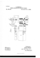
- Figure l is a view in side elevation of a part of the ink" table and two distributing rollers.
- Fig. 2 is 4o a top or plan view of the same.
- A designates the usual ink-table and C C the distributing rollers, arranged at an angle over the ink-table in the usual manner.
- Small auxiliary 4 5 distributingrollers d, d are shown as resting on top of the main distributing rollers.
- the said rollers C C operate to distribute the ink upon the ink-table after the latter-,has been supplied by means of a feed roller from the Patent No. 527,391, dated october 9, 1894.
- B is a horizontal frictional bearing surface formed ⁇ upon or secured to theink table adjacent to the outer end of the same, and D D engage frictionally with the bearing surface B.
- said bearing surface is formed on an arm or prothe ink-table and extends outwardlybeyond the same so as to sustain the said bearing surface in position to engage the friction disks or collars on the distributing rollers before the said rollers.
- the )said bearing surface may be formed upon or attached to the table itself or may be a projection integral therewith, the particular construction of the parts in the horizontal or working surface ofthe inking table so that said bearing surface will engage the rollers before the advance edge of the table comes in contact with the same.
- the inking rollers have been rotated solely by contact of the inktable therewith and inasmuch as the rollers arestationary when the ink-table strikes them and it requires some force to overcome their inertia and as the rollers themselves are made of composition of a soft and yielding character, they are likely to be torn or frayed at their ends where the table first strikes 5o ink fountain to the ink table, which latter, as
- the latter may be provided with a surface, as b, of leather or any other flexible or elastic material, or the said disks or collars D may be similarly covered' with leather or elastic material, or may be entirely made from raw-hide or similar substance, andwhen necessary, boththebea-ring'y surface and the said disks ror collarsimay bec-f made of yielding or ilexible material.
Landscapes
- Engineering & Computer Science (AREA)
- Mechanical Engineering (AREA)
- Inking, Control Or Cleaning Of Printing Machines (AREA)
Description
(No'Model.) S
R. MIEHLB. INKING APPARATUS FOR PRINTING PRESSES. No. 527,391.
Patented Oct. 9, 1894.
i Umanistica;
FPA-TENTOFFICE.
ROBERT MIRHLE, or CHICAGO, ILLINOIS, AssreNoR, BY Mnsnn4 ASSIGNMENTS,
TO TI-IE'MIEI-ILE PRINTING PRESS ILLINOIS. V H y AND MANUFACTURING COMPANY, OF
INKING APPARATUS-son PRINTING-PRESSES.
, i SPECIFICATION forming part of Letters l Application nettime 11.. 189e.
To @ZZ whom it may concern.- j Be it known that I, ROBERT MIEHLE, a citif zen of the United States, residing at Chicago, in the county of Cook and State of Illinois,
5 have invented a certain new and useful Im?" provement in Inking Apparatus for Printing- Presses, which is fully set forth in the following specification, reference being had tothe accompanying drawings.
This invention relates to the inkingapparatus of cylinder printigg presses of that class having a reciprocating ink-table which is connected and moves with the type bed and inkdistributing rollers arranged angularly upon the machine `frame and adapted to act upon the ink-table to distribute the ink thereon.
The object of my invention is to provide a simple means for imparting an initial rotary motion to the distributing rollers at a speed zo corresponding, or nearly so, with the speed of movement of the ink-table, thereby preventing the said distributing rollers being torn or injured at their ends which are` first encountered by the ink-table, as is liable to occur in presses as heretofore made when the ink-table alone is relied upon as a means of starting the distributing rollers when the table reaches the same on its return movement after charging the from rollers with ink.
In the accompanying drawings, I have shown only a part of the ink-table and four distributing rollers with my invention applied thereto; other parts of the machine and inking apparatus it being thought unnecessary 3 5 to show as these parts are of familiar construction. i
As illustrated in said drawings: Figure l is a view in side elevation of a part of the ink" table and two distributing rollers. Fig. 2 is 4o a top or plan view of the same.
As shown in said drawings, A designates the usual ink-table and C C the distributing rollers, arranged at an angle over the ink-table in the usual manner. Small auxiliary 4 5 distributingrollers d, d, are shown as resting on top of the main distributing rollers. The said rollers C C operate to distribute the ink upon the ink-table after the latter-,has been supplied by means of a feed roller from the Patent No. 527,391, dated october 9, 1894.
seanruetauo. ma mtas.)
usual, formspart of or is bolted to the type catory movement. f
B is a horizontal frictional bearing surface formed `upon or secured to theink table adjacent to the outer end of the same, and D D engage frictionally with the bearing surface B. In the particular construction shown, said bearing surface is formed on an arm or prothe ink-table and extends outwardlybeyond the same so as to sustain the said bearing surface in position to engage the friction disks or collars on the distributing rollers before the said rollers. The )said bearing surface may be formed upon or attached to the table itself or may be a projection integral therewith, the particular construction of the parts in the horizontal or working surface ofthe inking table so that said bearing surface will engage the rollers before the advance edge of the table comes in contact with the same.
In the operation of the device constructed as described, it is obvious that as the ink-table moves toward the distributing rollers C C, as seen in Fig. 1, the bearing surface B will strike the friction disk or collar D and impart an initial rotary motion to the rollers C C beforethe ink-table comes in contact with the saine, thereby giving the surface of the rollers the same, or approximately the same, speed as the surface of the ink-table so that when the ink-table reaches and passes beneath the rollers the latter will ride freely over or upon the ink-table.
As heretore constructed the inking rollers have been rotated solely by contact of the inktable therewith and inasmuch as the rollers arestationary when the ink-table strikes them and it requires some force to overcome their inertia and as the rollers themselves are made of composition of a soft and yielding character, they are likely to be torn or frayed at their ends where the table first strikes 5o ink fountain to the ink table, which latter, as
them.` By the use of the frictional bearing bed and moves with the latter in its reciproare disks or collars mountedupon the ends-of the distributing rollers y(l C and adapted to jection which is bolted to theside margin of n the surface of the table comes in contact with this respect being immaterial' provided the said bearing surface is located in advance of motion beforeI thel inking table reachesthe same. I i
It will beA understoodthat after-:the distributing roller is fully in contactwith the inktable, any further action ofthe bearing'sur.- face is unnecessary inasmuch asmotionwill bethen transmittedfromthe ink .table to the J surface arrangedv in! advance ofthe ink-table, therollers are' given a rotary movement so that their surfaces move at approximately the same speed as the ink-table so that p ractically no strain of a kind tending to tear the same will come upon therollers.
InV ordertofsecurebetter frictional engagement betweenthev disks or collars D Dfaudf the bearing surface B, the latter may be provided with a surface, as b, of leather or any other flexible or elastic material, or the said disks or collars D may be similarly covered' with leather or elastic material, or may be entirely made from raw-hide or similar substance, andwhen necessary, boththebea-ring'y surface and the said disks ror collarsimay bec-f made of yielding or ilexible material.
I am aware that ithas been proposed here tofore to positively actuatethe, form andinking rollers ofa printing pressby meansiof a rack on the type bed engaging gears'for pin.- ions onthei'nkingrollers. I am al'soawarethat it has been proposed to regulate `thepressure ofthe inkingrollers againsttheform by means distrlrauting.rollers withoutliabili'ty of injury fte-the latter and for this reason'` saidbearing B preferably does not extend along the sides of the ink table but terminates adjacent to the forward end thereof said bearing surface .beingmade only long` enoughrtoinsure that 'I the rollers'haveacquiredthenecessaryspeed of` rotation before striking the ink table. Similarly, no special means is requiredfor reversing the direction of movement of the distribputing: rollers .when thel ink table changes diirecti'on of'movement aty the extreme limit of its movement toward the distributing rollers,
for the reason that the rollers, being in con-.
A"tact with the table throughoutl their entire ;;lengthfthere;is-nodanger of tearing or mutiv lation of the composition at such time owing to the fact thatgthe strainA or pull upon the i compositionioccurring'atthe time of. reversal j; by reason of .theinertia of the-roller willbe j; distributed; throughout the entire length: of j the-same and willlnot'be so great at any one `j-pointas-te causerinjury.k
Iclaim as. my invention- In a printingpress,v the comhinationwith angularlyA arranged distributing. rollers pro- I vided withvv frictionaLdisks ,or collars, off a reciprocating ink-table provided with a fricl tionallbearingsurfa'e ylocatedadjacent.to the end ofthe table and extending. beyondthe ,samer saidy surface beingy adapted. to. engage said disks' or collarsffon thedistributing roll- 'ersinsuch manner as to-y give-anrinitial ro- ,taryrmovement thereto before. theii'nk-table c j` strikes thezsame, substantially asdescribed. In testimony whereofI affix my signature in presence ,i of two witnesses.
RoBE-RT Witnesses:
L. PETrERsoN, CHAs. B. SWEET.
Publications (1)
| Publication Number | Publication Date |
|---|---|
| US527391A true US527391A (en) | 1894-10-09 |
Family
ID=2596181
Family Applications (1)
| Application Number | Title | Priority Date | Filing Date |
|---|---|---|---|
| US527391D Expired - Lifetime US527391A (en) | Inking apparatus for printing-presses |
Country Status (1)
| Country | Link |
|---|---|
| US (1) | US527391A (en) |
-
0
- US US527391D patent/US527391A/en not_active Expired - Lifetime
Similar Documents
| Publication | Publication Date | Title |
|---|---|---|
| US527391A (en) | Inking apparatus for printing-presses | |
| US479579A (en) | Printing-press | |
| US1452043A (en) | Inking mechanism | |
| US9408A (en) | Cylinder printing-press | |
| US650853A (en) | Inking apparatus for printing-presses. | |
| US625771A (en) | huber | |
| US701698A (en) | Printing-press. | |
| US682951A (en) | Dog-trip for printing-presses. | |
| US873267A (en) | Ink-distributing mechanism for printing-presses. | |
| US4756A (en) | m-abston | |
| US603496A (en) | burnham | |
| US851016A (en) | Inking apparatus for printing-presses. | |
| US520346A (en) | Apparatus foe printing presses | |
| US416587A (en) | Printing-press | |
| US335196A (en) | Ington | |
| US142457A (en) | Improvement in inking apparatus | |
| US604719A (en) | Peesses | |
| US824732A (en) | Roller-protector for printing-presses. | |
| US559000A (en) | Signments | |
| US737829A (en) | Printing-press. | |
| US99101A (en) | William t | |
| US84403A (en) | Improvement in printing-presses | |
| US909339A (en) | Automatic ink-distributer for printing-presses. | |
| US842974A (en) | Front-stop-operating mechanism for printing-machines. | |
| US175036A (en) | Improvement in printing-presses |