US5263422A - Protected gate lock for hopper cars - Google Patents
Protected gate lock for hopper cars Download PDFInfo
- Publication number
- US5263422A US5263422A US07/986,279 US98627992A US5263422A US 5263422 A US5263422 A US 5263422A US 98627992 A US98627992 A US 98627992A US 5263422 A US5263422 A US 5263422A
- Authority
- US
- United States
- Prior art keywords
- door
- drive shaft
- ratchet wheel
- pawl
- teeth
- Prior art date
- Legal status (The legal status is an assumption and is not a legal conclusion. Google has not performed a legal analysis and makes no representation as to the accuracy of the status listed.)
- Expired - Lifetime
Links
- 230000005484 gravity Effects 0.000 claims abstract description 7
- 238000007789 sealing Methods 0.000 claims description 19
- 239000011236 particulate material Substances 0.000 claims description 7
- 230000000712 assembly Effects 0.000 description 15
- 238000000429 assembly Methods 0.000 description 15
- 230000007246 mechanism Effects 0.000 description 10
- 238000003466 welding Methods 0.000 description 3
- 229920003023 plastic Polymers 0.000 description 2
- 239000004033 plastic Substances 0.000 description 2
- 229920001084 poly(chloroprene) Polymers 0.000 description 2
- XAGFODPZIPBFFR-UHFFFAOYSA-N aluminium Chemical compound [Al] XAGFODPZIPBFFR-UHFFFAOYSA-N 0.000 description 1
- 229910052782 aluminium Inorganic materials 0.000 description 1
- 238000005266 casting Methods 0.000 description 1
- 230000006835 compression Effects 0.000 description 1
- 238000007906 compression Methods 0.000 description 1
- 229920001971 elastomer Polymers 0.000 description 1
- 238000003780 insertion Methods 0.000 description 1
- 230000037431 insertion Effects 0.000 description 1
- YAFQFNOUYXZVPZ-UHFFFAOYSA-N liproxstatin-1 Chemical compound ClC1=CC=CC(CNC=2C3(CCNCC3)NC3=CC=CC=C3N=2)=C1 YAFQFNOUYXZVPZ-UHFFFAOYSA-N 0.000 description 1
- 238000000034 method Methods 0.000 description 1
- 238000012986 modification Methods 0.000 description 1
- 230000004048 modification Effects 0.000 description 1
- 230000002459 sustained effect Effects 0.000 description 1
Images


Classifications
-
- B—PERFORMING OPERATIONS; TRANSPORTING
- B61—RAILWAYS
- B61D—BODY DETAILS OR KINDS OF RAILWAY VEHICLES
- B61D7/00—Hopper cars
- B61D7/14—Adaptations of hopper elements to railways
- B61D7/16—Closure elements for discharge openings
- B61D7/24—Opening or closing means
- B61D7/26—Opening or closing means mechanical
Definitions
- the invention relates to a lock for the gate which closes the discharge opening of a hopper railway car or truck, which prevents opening of the gate until the lock has been released and which holds the gate in its closed position after the gate has been closed.
- Gates, or sliding doors, for closing and sealing a discharge opening in a hopper car are well known in the art. See, for example, U.S. Pat. Nos. 2,926,963; 2,962,325; 3,956,996; 4,301,741; 4,360,295; 4,388,026; 4,450,773 and 4,617,868.
- the gate closes an opening in the bottom of a car to retain the lading, which usually is particulate in the car until it is desired to discharge the lading from the car.
- the gate is moved from its closed position to uncover the opening and permit the discharge of the lading.
- the force to move the gate is small relative to the force required when the car is full and the lading contacts the gate.
- the force of gravity is used to assist and maintain the closing of the gate of an empty car.
- a manually operable mechanism is used for opening and closing the gate and various devices are used for locking the mechanism when the gate is closed.
- Such manually operable mechanism can, for example, be a rack or racks secured to the gate and having teeth engageable with the teeth of one or more manually rotatable pinion gears mounted on a shaft having an end, which is square in cross-section, for receiving a wrench or tool or which has through holes for receiving a rod or bar, for rotating the shaft and the pinion gear or gears in one direction or another for opening and closing the gate.
- a seal such as a wire sealing band, may be attached to the locking device so that the latter cannot be unlocked without breaking the seal.
- a problem with prior art gate operating mechanisms is that workmen often attempt to rotate the rotatable shaft carrying the pinion gear or gears without opening or releasing the lock and cause damage to the lock gate and/or drive system.
- Another problem is that resilient seals for sealing the gate to the periphery of the discharge opening develop set and wear so that a lock which operates only in one position of the gate does not, after a period of use, hold the gate in a position which provide a satisfactory seal between the gate and the periphery of the discharge opening.
- One object of the invention is to prevent access of a workman to the manually operable component, such as the rotatable shaft, until the lock has been opened or released.
- Another object of the invention is to provide a simple device which prevents access to the manually operable component until such device is moved and movement of such device causes unlocking or release of the lock.
- Another object of the invention is to provide an incremental locking method by which the gate closure plate may be lockably engaged in a number of travel positions, these positions being in close enough increments to allow for contact and compression of the resilient gasket, thereby assuring a tight seal.
- Another object of the invention is to provide a positive, one-way-travel lock which will permit the closure plate, if left open at the unloading facility, to work its way closed as a result of the normal in-transit draft and buff impacts sustained by the freight car.
- Another object of the invention is to provide a mechanism which is readily visible and understandable to the operating personnel. All of the functioning devices, the closure seal fastening holes, the locking mechanism and the bar/drive stud operating casting with which the operation is involved, are located within inches of each other. None is under the car or otherwise hidden from view and therefore, the operator's task is simplified.
- a toothed rack is secured to the underside of a gate or door in the form of a slidable plate which, in its closed position, closes an opening at the bottom of the car through which lading in the car can be discharged.
- the slidable plate is movable from its closed position to an open position, partially open or fully open, in which the lading can pass through the opening, by pinion gears mounted on a tubular shaft rotatably mounted on the car and having teeth engaging the teeth of the rack.
- the shaft has ends at opposite sides of the car which are accessible when the access preventing device is suitably operated and which have at least one portion, such as a non-circular portion or a portion with through-holes, for receiving a tool for rotating the shaft.
- a ratchet wheel mounted on, and secured to, the shaft for rotation therewith.
- a tube pivotally mounted on the car and having U-shaped arms at opposite sides of the car which arms and a tie-down plate extending between the legs of the U-shaped arms cover the tool receiving portions of the shaft when the arms are in the locked position.
- the tube carries a pawl which, in the locked position of the arms, engages the ratchet wheel and prevents rotation of the shaft and hence, movement of the gate in the opening direction.
- the ratchet wheel and pawl When a car with the invention is in transit, the ratchet wheel and pawl permit the gate to move in only the closed direction.
- the slidable closure plate forming the gate is curved transversely to the direction of sliding and is carried by curved tracks which cause the gate to move upwardly with respect to the discharge opening as the gate is moved toward the open position.
- the closure plate in the absence of constraint in the closing direction by the ratchet wheel and pawl, the closure plate is urged by gravity toward the closed position so that if the car is bumped or jostled the closure plate moves only toward its closed position. If such movement is sufficient, the ratchet wheel and pawl, which provide small locking increments, will hold the closure plate in its newly assumed position.
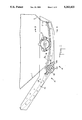
- FIGS. 1 and 2 are, respectively, side and top, fragmentary and schematic views of a hopper car including the invention
- FIG. 3 is an end elevation cross-sectional view, taken along the line 3--3 indicated in FIG. 1, of the embodiment shown in FIGS. 1 and 2;
- FIG. 4 is an enlarged, fragmentary end elevation view of the embodiment shown in FIGS. 1 and 2 and is taken along the line 4--4 indicated in FIG. 1;
- FIG. 5 is an enlarged, fragmentary side elevation view, partly in cross-section of the embodiment shown in FIGS. 1 and 2;
- FIG. 6 is an enlarged fragmentary view of the ratchet wheel and pawl assembly used in the embodiments shown in FIGS. 1 and 2;
- FIG. 7 is an enlarged, fragmentary, top view of the apparatus shown in FIGS. 1 and 2 with the parts in their unlocked positions;
- FIG. 8 is similar to FIG. 5 but shows the parts in their unlocked positions and illustrates the engagement of a tool with the rotatable shaft which carries the pinion gears which move the gate.
- a railway car may have more than one hopper and although the invention has application to hoppers on other vehicles and to stationary hoppers, the invention will be described in connection with one conventional railway car hopper, the application of the invention to other hoppers being apparent to those skilled in the art.
- the hopper has sloping side walls, or slope sheets, 1 and 2, and sloping end walls 3 and 4.
- the sidewall 2 has an extension 2' secured to the sidewall 2, such as by welding.
- the end walls 3 and 4 have vertical extensions 3' and 4' secured thereto, such as by welding.
- the hopper has a trough with cap structures 5 and 6 of the type described in U.S. Pat. No. 4,934,877 for pneumatic removal of the particulate material, but since such trough and cap structures 5 and 6 do not form part of the present invention, a detailed description thereof is not necessary herein.
- the hopper has an opening 7 which is openable or closable by a door or gate 8, the door 8 being in an open position in FIG. 8 and in a closed position in FIGS. 1, 2 and 5.
- the door or gate 8 comprises a curved plate 8a of aluminum (see FIGS. 1, 3 and 5) which, at its ends adjacent the extensions 3' and 4', has secured thereto, by bolts 9, strips of hard plastic 10 and 11 and a sealing strip 12 of rubber, such as neoprene rubber (see FIG. 3).
- the door 8 is concave, or curved downwardly, with respect to the direction of its movement from its closed position to its open position for reasons set forth hereinafter.
- the door or gate 8 rides on a pair of supports or rails 13 and 14 (see FIGS. 1, 2, 3 and 8) which have a curvature corresponding to the curvature of the door 8 and which are secured to the extensions 3' and 4', such as by bolts 15.
- the supports 13 and 14 curve upwardly from the edge of the opening 7.
- the door 8 is unrestrained with respect to movement to the closed position, except by friction which is reduced by the plastic strips 11 and by particulate material passing through the opening 7, and it will normally tend to assume its closed position when the particulate material has been discharged, particularly if the vehicle carrying the hopper is jostled or bumped.
- extension 2' has a sealing strip 16, such as a seal of neoprene rubber, which extends from one extension 3' to the opposite extension 4' and which is secured to the extension 2', such as by bolts 17.
- a sealing strip 16 such as a seal of neoprene rubber
- the rear end of the door 8 carries a similar sealing strip 18 secured to the door 8, such as by bolts 19, which engages a lip 1' on the sidewall 1 when the door 8 is closed.
- the opening 7 is closed and is sealed by the sealing strips 16, 18 and 12.
- a pair of curved, toothed racks 20 and 21 Secured to the bottom side of the curved plate 8a are a pair of curved, toothed racks 20 and 21 (see FIGS. 3 and 5), the teeth of which engage with the teeth on a pair of gears 22 and 23 (see FIGS. 4, 5 and 8).
- the gears 22 and 23 are rotated clockwise, as viewed in FIGS. 5 and 8, the door 8 is moved toward its closed position, and when the gears 22 and 23 are rotated counterclockwise, as viewed in FIG. 5, the door 8 is moved toward its open position.
- the gears 22 and 23 are secured to a drive shaft 24 for rotation therewith (see FIGS. 4 and 7).
- the drive shaft 24 is tubular and comprises three parts, an end part 25, a middle part 26 and a center part 27.
- the center part 27 is rotatable in bearings 28 and 29 held by supports 30 and 31 secured to the extensions 3' and 4' of the hopper end walls in any conventional manner.
- the drive shaft 24 has a pair of capstan assemblies 32 and 33 which are secured to opposite ends of the center shaft part 27 by bolts 34 so that when an assembly 32 or 33 is rotated, the shaft 24 and hence, the gears 22 and 23 are rotated to open or close the door 8.
- Each assembly 32 and 33 comprises an end portion 35 (see FIGS. 4, 5 and 7) with a square cross-section and grooves 36 for receiving a power driven, axially applied, rotating tool of a known type and a through-opening 37 for receiving a long bar 42 (see FIG. 8) for manually rotating the drive shaft 24 in the event that the power driven rotating tool is not available or used.
- Each assembly comprises a tube 38 which fits over the center shaft section 27 and is secured to the latter by the bolt 34. The tube 38 is rotatable with the assembly.
- Each assembly 32 and 33 includes a seal wheel 39 which has a plurality of openings 40 (see FIGS. 1, 5 and 8) for receiving a seal as hereinafter described.
- the wheel 39 is secured to the assembly so as to be rotatable with the assembly.
- a toothed ratchet wheel 41 is also secured to the center shaft section 27 so as to be rotatable thereby and so that if the ratchet wheel 41 is prevented from rotating the drive shaft 24 is prevented from rotating.
- the apparatus of the invention has two locking means comprising pivotally mounted handle assemblies 43 and 44, the assembly 43 being shown in enlarged detail in FIG. 7.
- Each assembly has a U-shaped arm 45 and 46 which is spaced from the ends of the capstan assemblies 33 and 32, respectively, but which intersects the axis of the capstan assemblies when the handles are in a first, locking position so that a rotating tool cannot be applied axially of the assemblies 32 and 33.
- bridging plates 47 and 48 are secured to the handles 45 and 46, such as by welding, and are positioned so as to prevent access to the openings 37 in the assemblies 32 and 33 from the top side of the assemblies 32 and 33 by a tool, such as the bar (FIG. 8) for rotating the assemblies 32 and 33 and hence, the drive shaft 24.
- the handles 45 and 46 are tubular, carry spacing collars 49 and 50 secured thereto and are interconnected by a tube 51 secured to the handles 45 and 46, such as by bolts 52.
- a tube 51 secured to the handles 45 and 46 such as by bolts 52.
- the handle assembly 44 and the capstan 32 can be omitted if desired.
- the bridging plates 47 and 48 have openings 53 (FIGS. 2, 4 and 7) for receiving a seal as hereinafter described.
- the collar 49 has a pawl 54 mounted thereon and secured thereto with its free end engageable with the teeth 41a of the ratchet wheel 41.
- the pawl 54 In FIG. 6, the pawl 54 is in the locking position and in FIG. 7, the pawl 54 is in the unlocked position.
- the pawl 54 when it is in the locking position, prevents rotation of the ratchet wheel 41 in the direction of the arrow 55 (FIG. 6) but permits the ratchet wheel 41 to rotate in the opposite direction.
- the pawl 54 is in the unlocked position (FIG. 7)
- the ratchet wheel 41 is free to rotate in either direction.
- the pawl 54 is pivotable into the locked and unlocked positions by the handles 45 and 46.
- the pawl 54 has a projection 56 which is engaged by one end of a torsion spring 57, and the opposite end of the spring 57 engages a pin 58 fixedly mounted on the end wall extension 4'.
- the spring 57 is selected and mounted so that it continuously urges the free end of the pawl 54 toward the teeth 41a even when the pawl 54 is in the locked position shown in FIG. 6 so that when the railway car is in transmit, the pawl 54 will not become disengaged from the ratchet wheel 41 due to bouncing or bumping of the car.
- the mechanism for opening the hopper door is sealed so that the receiver of the lading can ascertian that there has been no removal of lading.
- the locking means of the invention can be sealed by conventional wire seals 59 and 60 which extend through an opening 53 in the bridging plates 47 and 48 and an opening 40 in the sealing wheel 39.
- the seals 59 and 60 must be broken by movement of the handles 45 or 46 or be cut before the locking means can be moved from the locking position to the unlocking position.
- the locking means will permit the door 8 to be moved to a fully closed position manually or because of the action of gravity on the door 8 even if the fully closed position is not the same as when the sealing strips 16 and 18 were new.
- the spacing between the teeth 41a on the ratchet wheel 41 and the movement of the door 8 by the drive shaft 24, the gears 22 and 23 and the racks 20 and 21 is selected so that when the door 8 moves no more than one-quarter inch, the pawl 54 moves from one tooth 41a to the next adjacent tooth 41a on the ratchet wheel 41.
- the pawl 54 can lock the ratchet wheel 41 when the door 8 is at least within one-quarter inch of the fully closed position of the door 8.
- the locking mechanism is effective to lock the door 8 in positions which are one-quarter inch apart or less, thereby providing a good seal between the door 8 and the hopper side walls regardless of the condition of the sealing strips 16 and 18 or the failure of workman to fully close the door 8.
- the locking mechanism permits the workman closer increments of closing of the door 8 so that the workman does not have to select a position of the door 8 in which there is a substantial gap between the door 8 and the sealing strips 16 and/or 18.
Landscapes
- Engineering & Computer Science (AREA)
- Transportation (AREA)
- Mechanical Engineering (AREA)
- Specific Sealing Or Ventilating Devices For Doors And Windows (AREA)
- Lock And Its Accessories (AREA)
Abstract
Description
Claims (12)
Priority Applications (2)
| Application Number | Priority Date | Filing Date | Title |
|---|---|---|---|
| US07/986,279 US5263422A (en) | 1992-12-07 | 1992-12-07 | Protected gate lock for hopper cars |
| CA002108218A CA2108218C (en) | 1992-12-07 | 1993-10-12 | Protected gate lock for hopper cars |
Applications Claiming Priority (1)
| Application Number | Priority Date | Filing Date | Title |
|---|---|---|---|
| US07/986,279 US5263422A (en) | 1992-12-07 | 1992-12-07 | Protected gate lock for hopper cars |
Publications (1)
| Publication Number | Publication Date |
|---|---|
| US5263422A true US5263422A (en) | 1993-11-23 |
Family
ID=25532263
Family Applications (1)
| Application Number | Title | Priority Date | Filing Date |
|---|---|---|---|
| US07/986,279 Expired - Lifetime US5263422A (en) | 1992-12-07 | 1992-12-07 | Protected gate lock for hopper cars |
Country Status (2)
| Country | Link |
|---|---|
| US (1) | US5263422A (en) |
| CA (1) | CA2108218C (en) |
Cited By (10)
| Publication number | Priority date | Publication date | Assignee | Title |
|---|---|---|---|---|
| WO2001010698A1 (en) * | 1999-08-11 | 2001-02-15 | Miner Enterprises, Inc. | Locking mechanism for a hinged railroad hopper car door |
| US6736297B2 (en) | 2001-03-02 | 2004-05-18 | Timpte Inc. | Belt trap door closure |
| US20050056185A1 (en) * | 2003-08-26 | 2005-03-17 | Herzog John C. | Railcar with discharge control system |
| US20050056186A1 (en) * | 2003-08-26 | 2005-03-17 | Creighton George S. | Railway hopper car with longitudinal discharge openings |
| US20050087095A1 (en) * | 2003-10-09 | 2005-04-28 | Barry Robert J. | Universal boxcar |
| US6907914B1 (en) * | 2000-05-05 | 2005-06-21 | Jöran Lundh | Locking device |
| US20060016104A1 (en) * | 2004-07-07 | 2006-01-26 | Metso Minerals ( Tampere) Oy | Feeder hopper, a method for locking the walls of a feeder hopper and a locking means |
| US20090235840A1 (en) * | 2008-03-21 | 2009-09-24 | Early Stephen R | Hopper car gate with a curved door |
| US7735426B2 (en) | 2004-08-10 | 2010-06-15 | Trinity Industries, Inc. | Hopper cars with one or more discharge control systems |
| US8915194B2 (en) | 2004-08-10 | 2014-12-23 | Trinity Industries, Inc. | Hopper cars with one or more discharge control systems |
Citations (14)
| Publication number | Priority date | Publication date | Assignee | Title |
|---|---|---|---|---|
| US278343A (en) * | 1883-05-29 | Dumping-car | ||
| US1305351A (en) * | 1919-06-03 | stamslaw gandek | ||
| US1692276A (en) * | 1928-11-20 | Dump gar | ||
| US2668684A (en) * | 1949-06-18 | 1954-02-09 | Walter F Metzger | Dustproof damper |
| US2738737A (en) * | 1952-04-26 | 1956-03-20 | Entpr Railway Equipment Co | Discharge outlet for hopper |
| US3138117A (en) * | 1958-06-30 | 1964-06-23 | Entpr Railway Equipment Co | Sliding hopper closure housing outlet assembly |
| US3461817A (en) * | 1967-05-19 | 1969-08-19 | Miner Inc W H | Plug seal for hopper outlet assembly |
| US3958514A (en) * | 1973-12-28 | 1976-05-25 | Acf Industries, Incorporated | Automatic hopper gate locking mechanism |
| US4094252A (en) * | 1976-04-22 | 1978-06-13 | Hendrik Pater | Self-controlled on-grade monorail track switch and method |
| US4099464A (en) * | 1976-03-01 | 1978-07-11 | Imperial Chemical Industries Limited | Shaped explosive charge casing |
| US4112852A (en) * | 1976-12-27 | 1978-09-12 | Koranda Clarence J | Railway hopper car labyrinth gate seal |
| US4224879A (en) * | 1978-06-12 | 1980-09-30 | Keystone Industries, Inc. | Railway hopper car door latch |
| US4248158A (en) * | 1979-05-14 | 1981-02-03 | Holland Company | Railway hopper car gate outlet actuating mechanism |
| US4360295A (en) * | 1980-06-25 | 1982-11-23 | North American Car Corporation | Combination gravity/pneumatic hopper bottom |
-
1992
- 1992-12-07 US US07/986,279 patent/US5263422A/en not_active Expired - Lifetime
-
1993
- 1993-10-12 CA CA002108218A patent/CA2108218C/en not_active Expired - Lifetime
Patent Citations (14)
| Publication number | Priority date | Publication date | Assignee | Title |
|---|---|---|---|---|
| US278343A (en) * | 1883-05-29 | Dumping-car | ||
| US1305351A (en) * | 1919-06-03 | stamslaw gandek | ||
| US1692276A (en) * | 1928-11-20 | Dump gar | ||
| US2668684A (en) * | 1949-06-18 | 1954-02-09 | Walter F Metzger | Dustproof damper |
| US2738737A (en) * | 1952-04-26 | 1956-03-20 | Entpr Railway Equipment Co | Discharge outlet for hopper |
| US3138117A (en) * | 1958-06-30 | 1964-06-23 | Entpr Railway Equipment Co | Sliding hopper closure housing outlet assembly |
| US3461817A (en) * | 1967-05-19 | 1969-08-19 | Miner Inc W H | Plug seal for hopper outlet assembly |
| US3958514A (en) * | 1973-12-28 | 1976-05-25 | Acf Industries, Incorporated | Automatic hopper gate locking mechanism |
| US4099464A (en) * | 1976-03-01 | 1978-07-11 | Imperial Chemical Industries Limited | Shaped explosive charge casing |
| US4094252A (en) * | 1976-04-22 | 1978-06-13 | Hendrik Pater | Self-controlled on-grade monorail track switch and method |
| US4112852A (en) * | 1976-12-27 | 1978-09-12 | Koranda Clarence J | Railway hopper car labyrinth gate seal |
| US4224879A (en) * | 1978-06-12 | 1980-09-30 | Keystone Industries, Inc. | Railway hopper car door latch |
| US4248158A (en) * | 1979-05-14 | 1981-02-03 | Holland Company | Railway hopper car gate outlet actuating mechanism |
| US4360295A (en) * | 1980-06-25 | 1982-11-23 | North American Car Corporation | Combination gravity/pneumatic hopper bottom |
Cited By (25)
| Publication number | Priority date | Publication date | Assignee | Title |
|---|---|---|---|---|
| US6227124B1 (en) * | 1999-08-11 | 2001-05-08 | Miner Enterprises, Inc. | Locking mechanism for a hinged railroad hopper car door |
| WO2001010698A1 (en) * | 1999-08-11 | 2001-02-15 | Miner Enterprises, Inc. | Locking mechanism for a hinged railroad hopper car door |
| US6907914B1 (en) * | 2000-05-05 | 2005-06-21 | Jöran Lundh | Locking device |
| US6736297B2 (en) | 2001-03-02 | 2004-05-18 | Timpte Inc. | Belt trap door closure |
| AU2004268992B9 (en) * | 2003-08-26 | 2010-05-20 | Trinity Industries, Inc. | Railway hopper car with longitudinal discharge openings |
| AU2004268992B2 (en) * | 2003-08-26 | 2010-01-14 | Trinity Industries, Inc. | Railway hopper car with longitudinal discharge openings |
| US20050056186A1 (en) * | 2003-08-26 | 2005-03-17 | Creighton George S. | Railway hopper car with longitudinal discharge openings |
| US7891304B2 (en) | 2003-08-26 | 2011-02-22 | Trinity Industries, Inc. | Railcar with discharge control system |
| US7051661B2 (en) | 2003-08-26 | 2006-05-30 | Trn Business Trust | Railcar with discharge control system |
| US7080598B2 (en) * | 2003-08-26 | 2006-07-25 | Trn Business Trust | Railway hopper car with longitudinal discharge openings |
| US20050056185A1 (en) * | 2003-08-26 | 2005-03-17 | Herzog John C. | Railcar with discharge control system |
| US7681507B2 (en) | 2003-08-26 | 2010-03-23 | Trn Business Trust | Railcar with discharge control system |
| US7210413B2 (en) | 2003-10-09 | 2007-05-01 | Trn Business Trust | Universal boxcar |
| US7261044B2 (en) | 2003-10-09 | 2007-08-28 | Trinity Industries, Inc. | Boxcar with load restraint system |
| US7305923B2 (en) | 2003-10-09 | 2007-12-11 | Trinity Industries, Inc. | Universal boxcar with exterior metal surfaces |
| US20050087095A1 (en) * | 2003-10-09 | 2005-04-28 | Barry Robert J. | Universal boxcar |
| US20090263194A1 (en) * | 2004-07-07 | 2009-10-22 | Metso Minerals Inc, | Feeder hopper, a method for locking the walls of a feeder hopper and a locking means |
| US7568858B2 (en) * | 2004-07-07 | 2009-08-04 | Metso Minerals Inc. | Feeder hopper, a method for locking the walls of a feeder hopper and a locking means |
| US20060016104A1 (en) * | 2004-07-07 | 2006-01-26 | Metso Minerals ( Tampere) Oy | Feeder hopper, a method for locking the walls of a feeder hopper and a locking means |
| US20110089717A1 (en) * | 2004-07-07 | 2011-04-21 | Metso Minerals Inc. | Feeder hopper, a method for locking the walls of a feeder hopper and a locking means |
| US8182172B2 (en) | 2004-07-07 | 2012-05-22 | Metso Minerals Inc. | Feeder hopper, a method for locking the walls of a feeder hopper and a locking means |
| US7735426B2 (en) | 2004-08-10 | 2010-06-15 | Trinity Industries, Inc. | Hopper cars with one or more discharge control systems |
| US8915194B2 (en) | 2004-08-10 | 2014-12-23 | Trinity Industries, Inc. | Hopper cars with one or more discharge control systems |
| US20090235840A1 (en) * | 2008-03-21 | 2009-09-24 | Early Stephen R | Hopper car gate with a curved door |
| US7819067B2 (en) * | 2008-03-21 | 2010-10-26 | Aero Transportation Products, Inc. | Hopper car gate with a curved door |
Also Published As
| Publication number | Publication date |
|---|---|
| CA2108218A1 (en) | 1994-06-08 |
| CA2108218C (en) | 1996-10-29 |
Similar Documents
| Publication | Publication Date | Title |
|---|---|---|
| US5353713A (en) | Apparatus for controlling operation of a railcar discharge gate assembly having a lost motion mechanism for unlocking the gate prior to movement | |
| US3187684A (en) | Rapid discharge hopper car | |
| CA2044478C (en) | Hopper door apparatus for a railway car | |
| US5785362A (en) | Cam-operated hatch cover lock | |
| US6279487B1 (en) | Railroad hopper car door assembly | |
| US5263422A (en) | Protected gate lock for hopper cars | |
| US4450773A (en) | Sliding gate for a railroad hopper car | |
| US20040149163A1 (en) | Manual railroad hopper car door actuating mechanism | |
| CA2079832C (en) | Unit for actuating gates of a hopper railroad car | |
| US4877276A (en) | Door control mechanism | |
| CA1331720C (en) | Unloading gate for bulk material handling containers | |
| US6405658B1 (en) | Manual discharge door operating system for a hopper railcar | |
| US3709152A (en) | Hopper car gate latching mechanism | |
| US3872796A (en) | Door operating mechanism | |
| US3938446A (en) | Door assemblies for closing rail car end openings | |
| US5507235A (en) | Gravity outlet | |
| US4094254A (en) | Lock for railway hopper car gate railway car gate lock | |
| CA1060711A (en) | Locking end actuating mechanism for railway hopper car doors | |
| US5448955A (en) | Gravity outlet latching mechanism | |
| US3796007A (en) | Door moving structure | |
| US6546611B1 (en) | Rail car anti-spin door handle and installation method | |
| US3877392A (en) | Automatic gate locking mechanism | |
| US2751860A (en) | Removable closure for discharged outlet for railway car hopper | |
| US4664038A (en) | Door latch control apparatus for hopper vehicle | |
| US3405655A (en) | Railway hopper car door operating mechanism lock |
Legal Events
| Date | Code | Title | Description |
|---|---|---|---|
| AS | Assignment |
Owner name: ELLCON NATIONAL, INC., SOUTH CAROLINA Free format text: ASSIGNMENT OF ASSIGNORS INTEREST.;ASSIGNOR:BAREFOOT, RICHARD;REEL/FRAME:006352/0825 Effective date: 19921123 |
|
| STCF | Information on status: patent grant |
Free format text: PATENTED CASE |
|
| FPAY | Fee payment |
Year of fee payment: 4 |
|
| FEPP | Fee payment procedure |
Free format text: PAYOR NUMBER ASSIGNED (ORIGINAL EVENT CODE: ASPN); ENTITY STATUS OF PATENT OWNER: SMALL ENTITY |
|
| FPAY | Fee payment |
Year of fee payment: 8 |
|
| FPAY | Fee payment |
Year of fee payment: 12 |
|
| AS | Assignment |
Owner name: AMSTED RAIL - FAIVELEY, LLC., ILLINOIS Free format text: ASSIGNMENT OF ASSIGNORS INTEREST;ASSIGNOR:ELLCON-NATIONAL, INC.;REEL/FRAME:025786/0557 Effective date: 20101001 |
|
| AS | Assignment |
Owner name: AMSTED RAIL COMPANY, INC., ILLINOIS Free format text: MERGER;ASSIGNOR:AMSTED RAIL - FAIVELEY, LLC;REEL/FRAME:040947/0866 Effective date: 20161219 |