US5261249A - Refrigerant handling system with auxiliary condenser flow control - Google Patents
Refrigerant handling system with auxiliary condenser flow control Download PDFInfo
- Publication number
- US5261249A US5261249A US07/977,083 US97708392A US5261249A US 5261249 A US5261249 A US 5261249A US 97708392 A US97708392 A US 97708392A US 5261249 A US5261249 A US 5261249A
- Authority
- US
- United States
- Prior art keywords
- refrigerant
- condenser
- set forth
- system set
- valve
- Prior art date
- Legal status (The legal status is an assumption and is not a legal conclusion. Google has not performed a legal analysis and makes no representation as to the accuracy of the status listed.)
- Expired - Lifetime
Links
- 239000003507 refrigerant Substances 0.000 title claims abstract description 138
- 238000009833 condensation Methods 0.000 claims description 6
- 230000005494 condensation Effects 0.000 claims description 6
- 238000000605 extraction Methods 0.000 claims 1
- 230000000153 supplemental effect Effects 0.000 description 33
- 238000010926 purge Methods 0.000 description 11
- 238000011084 recovery Methods 0.000 description 10
- 238000010586 diagram Methods 0.000 description 5
- 239000003921 oil Substances 0.000 description 5
- 238000000746 purification Methods 0.000 description 4
- 238000005057 refrigeration Methods 0.000 description 4
- 239000010725 compressor oil Substances 0.000 description 3
- 238000001816 cooling Methods 0.000 description 2
- CBENFWSGALASAD-UHFFFAOYSA-N Ozone Chemical compound [O-][O+]=O CBENFWSGALASAD-UHFFFAOYSA-N 0.000 description 1
- 230000033228 biological regulation Effects 0.000 description 1
- 238000010276 construction Methods 0.000 description 1
- 230000007423 decrease Effects 0.000 description 1
- 238000001704 evaporation Methods 0.000 description 1
- 230000008020 evaporation Effects 0.000 description 1
- 239000012530 fluid Substances 0.000 description 1
- 229910052736 halogen Inorganic materials 0.000 description 1
- 150000002367 halogens Chemical class 0.000 description 1
- 239000007788 liquid Substances 0.000 description 1
- 230000004048 modification Effects 0.000 description 1
- 238000012986 modification Methods 0.000 description 1
- 238000013021 overheating Methods 0.000 description 1
- 230000005855 radiation Effects 0.000 description 1
- 239000000523 sample Substances 0.000 description 1
- 238000000926 separation method Methods 0.000 description 1
- 238000011144 upstream manufacturing Methods 0.000 description 1
Images


Classifications
-
- F—MECHANICAL ENGINEERING; LIGHTING; HEATING; WEAPONS; BLASTING
- F25—REFRIGERATION OR COOLING; COMBINED HEATING AND REFRIGERATION SYSTEMS; HEAT PUMP SYSTEMS; MANUFACTURE OR STORAGE OF ICE; LIQUEFACTION SOLIDIFICATION OF GASES
- F25B—REFRIGERATION MACHINES, PLANTS OR SYSTEMS; COMBINED HEATING AND REFRIGERATION SYSTEMS; HEAT PUMP SYSTEMS
- F25B45/00—Arrangements for charging or discharging refrigerant
-
- F—MECHANICAL ENGINEERING; LIGHTING; HEATING; WEAPONS; BLASTING
- F25—REFRIGERATION OR COOLING; COMBINED HEATING AND REFRIGERATION SYSTEMS; HEAT PUMP SYSTEMS; MANUFACTURE OR STORAGE OF ICE; LIQUEFACTION SOLIDIFICATION OF GASES
- F25B—REFRIGERATION MACHINES, PLANTS OR SYSTEMS; COMBINED HEATING AND REFRIGERATION SYSTEMS; HEAT PUMP SYSTEMS
- F25B2345/00—Details for charging or discharging refrigerants; Service stations therefor
- F25B2345/002—Collecting refrigerant from a cycle
Definitions
- the present invention is directed to refrigerant handling systems, particularly refrigerant recovery systems, in which refrigerant is pumped by a compressor from an evaporator through a condenser in heat exchange relationship with each other.
- the condenser and evaporator are combined in a single assembly through which cooling air is circulated by a fan.
- Content of the storage container is monitored by a scale on which the container is mounted for sensing weight of liquid refrigerant in the container, and by a pressure switch coupled to the fluid conduit between the condenser and the container for sensing vapor pressure within the storage container.
- a full-container condition sensed at the scale or a high-pressure condition sensed at the pressure switch terminates operation of the compressor motor.
- a vacuum switch is positioned between the inlet valve and the evaporator for sensing evacuation of refrigerant from the refrigeration system and automatically terminating operation of the compressor motor.
- U.S. Pat. No. 4,768,347 also signed to the assignee hereof, discloses a refrigerant recovery system that includes a compressor having an inlet coupled through an evaporator and through a solenoid valve to the refrigeration equipment from which refrigerant is to be withdrawn, and an outlet coupled through a condenser to a refrigerant storage container or tank.
- the refrigerant storage container is carried by a scale having a limit switch coupled to control electronics to prevent or terminate further refrigerant recovery when the container is full.
- the scale comprises a platform pivotally mounted by a hinge pin to a wheeled cart, which also carries the evaporator/condenser unit, compressor, control electronics, and associated valves and hoses.
- the condenser and evaporator are combined within a single assembly, in heat exchange relationship with each other, which also includes oil separation and oil drain facility.
- U.S. Pat. No. 4,805,416 discloses refrigerant recovery and purification systems that include facility for operation of the compressor to withdraw recovered refrigerant from the storage container, circulate the refrigerant in a closed path through a filter/dryer, and then return the refrigerant to the storage container.
- a supplemental condenser may be positioned between the storage container and the primary condenser in the heat-exchange/oil-separator unit to provide enhanced condenser heat-rejection capability, and thereby facilitate extended operation of the unit in the purification mode without overheating the refrigerant or the compressor. All refrigerant from the compressor flows through both the primary condenser and supplemental condenser in both of the recovery and purification modes.
- a more specific object of the present invention is to provide a system, particularly a refrigerant recovery system of the character described above, that operates at approximately 10° F. superheat at the evaporator, and that maintains refrigerant temperature at the condenser to less than 25° F. above ambient or 45° F. above evaporator temperature as appropriate.
- a refrigerant handling system in accordance with the present invention includes a compressor and an evaporator for adding heat to refrigerant fed to the compressor inlet.
- a first condenser is connected to the compressor outlet and disposed in heat exchange relationship to the evaporator for at least partially condensing refrigerant vapor from the compressor by transfer of heat to refrigerant in the evaporator.
- a second condenser is not in heat exchange relationship with the evaporator.
- One or more valves are connected to the second condenser for selectively controlling refrigerant flow from the compressor outlet to the first and second condensers so as to maintain desired refrigerant condensing temperature--i.e., a maximum desired refrigerant temperature at the combined condenser outlet.
- the first and second condensers are connected in series with the compressor outlet, and the valves are connected for selectively bypassing refrigerant from the second condenser, while all refrigerant from the compressor outlet flows through the first condenser that is in heat exchange relation to the evaporator.
- the first or primary condenser is connected downstream of the second or supplemental condenser.
- the flow control valves in the preferred embodiments of the invention are responsive to refrigerant temperature at the condensers for selectively bypassing refrigerant from the second or supplemental condenser while directing all refrigerant through the first or primary condenser in heat exchange relation to the evaporator.
- the flow control valve may comprise a head pressure control valve connected at the inlet of the second condenser and responsive to condensing pressure within the second condenser, which varies as a function of condensing temperature at the second condenser, for selectively bypassing refrigerant from flow through the second condenser.
- the flow control valve comprises a solenoid valve responsive to electrical signals from a temperature sensor positioned for sensing refrigerant temperature at the outlet of the condensers.
- the flow control valve comprises a thermostatic expansion valve having at least one control bulb positioned so as to be responsive to condenser refrigerant temperature, and valve elements for selectively feeding refrigerant to the second or supplemental condenser when an elevated refrigerant temperature at the condenser indicates need for supplemental condenser operation.
- the thermostatic expansion valve may also include a second control bulb positioned to be responsive to either evaporator temperature or ambient temperature so as to control refrigerant flow through the valve and supplemental condenser as a function of a temperature differential between condenser refrigerant temperature and either evaporator or ambient temperature.
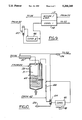
- FIG. 1 is a schematic diagram of a refrigerant recovery system in accordance with one embodiment of the invention
- FIG. 2 is a fragmentary schematic diagram that illustrates a portion of FIG. 1;
- FIGS. 3 is a fragmentary schematic diagram similar to that of FIG. 2 but illustrating a modified embodiment of the invention
- FIG. 4 is a sectional view that illustrates the flow control valve in the embodiments of FIGS. 2 and 3;
- FIGS. 5-6 are fragmentary schematic diagrams similar to a portion of FIG. 1 but illustrating further modified embodiments of the invention.
- FIGS. 7 and 8 are schematic drawings that illustrate respective flow control valves that may be employed in the embodiments of FIGS. 5-6;
- FIGS. 9-11 are fragmentary schematic diagrams that illustrates further embodiments of the invention.
- FIG. 1 illustrates a refrigerant recovery system 20 in accordance with one embodiment of the present invention as comprising inlet flow control hardware 22, including flow control valves, filters, etc., coupled to a connector 24 for connection to equipment under service from which refrigerant is to be withdrawn.
- Refrigerant from inlet flow control 22 is fed to an inlet port 26 at the upper portion of a heat-exchange/oil-separator unit 28.
- Unit 28 comprises a substantially cylindrical canister 30 having an open internal volume 31, with inlet port 26 and an outlet port 32 being mounted at the upper portion thereof and opening into the internal volume.
- refrigerant flows through a superheater 34 and a filter/dryer 36 to the inlet of a refrigerant compressor 38.
- An oil drain valve 40 is disposed at the bottom of canister 30.
- the outlet of compressor 38 is connected through a compressor oil separator 42 to a thermostatic expansion valve 50.
- Valve 50 receives a control input from a refrigerant bulb 51, and has a pair of outlets.
- the first outlet is connected to a condenser coil 44 within canister 30.
- the second output of valve 50 is connected to coil 44 through a supplemental condenser 46 cooled by a fan 48.
- the output of coil 44 flows through a superheater 34 to air purge hardware 52.
- Bulb 51 is positioned to be in heat exchange with refrigerant flowing to air purge 52, so that the control pressure applied to valve 50 by bulb 51 is responsive to condenser outlet refrigerant temperature.
- refrigerant is fed through a second filter/dryer 54 and outlet flow control hardware 56 to a connector 58 coupled to a refrigerant storage container 60.
- a pair of level sensors 62,64 are positioned within canister 30, and are coupled to flow control valves within inlet flow control hardware 22.
- connector 24 is connected to equipment from which refrigerant is to be recovered, and connector 58 is coupled to container 60.
- Fan 48 and compressor 38 are then energized, so that compressor 38 draws refrigerant from the equipment under service into open volume 31 of canister 30, in which heat exchange takes place between such inlet refrigerant and refrigerant flowing through condenser coil 44.
- internal volume 31 of canister functions as both an accumulator and an evaporator in which heat is withdrawn from refrigerant within coil 44 and added to refrigerant within the canister volume so as to vaporize inlet refrigerant while cooling and at least partially condensing refrigerant flowing through coil 44.
- Such vaporized refrigerant exits canister 30 at port 32, and is further heated within superheater 34 by heat exchange with refrigerant from condenser coil 44.
- the purpose of superheater 34 is to prevent condensation of refrigerant between the evaporator and the inlet of compressor 38 during operation at low ambient temperatures.
- Compressed refrigerant vapor is fed from compressor 38 through valve 50 to condenser coil 44, and thence through superheater 34 to air purge 52.
- all or a portion of such refrigerant may flow through supplemental condenser 46.
- refrigerant that is at least partially condensed flows to container 60 through air purge 52, filter/dryer 54 and outlet flow control 56.
- system 20 hereinabove described is essentially the same as that disclosed in U.S. application Ser. No. 07/797,360 filed Nov. 25, 1991 and assigned to the assignee hereof, to which reference may be made for more detailed discussion of overall system construction and operation.
- FIG. 2 illustrates functional interconnection of accumulator/evaporator 31 with condenser coil 44, separate supplemental condenser 46, valve 50 and bulb 51.
- Valve 50 is set in conjunction with refrigerant vapor pressure in bulb 51 so that, when temperature of refrigerant to air purge 52 is sufficiently high to indicate a need for further condensation, some or all of the refrigerant from compressor oil separate 42 is routed through supplemental condenser 46.
- the amount of refrigerant fed through and/or bypassing condenser 46 is thus determined by combined (primary and secondary) condenser outlet refrigerant temperature.
- FIG 3 illustrates a modification in which supplemental condenser 46 and valve 50 are positioned downstream of primary condenser 44, that is between primary condenser 44 and air purge 52.
- Bulb 51 is again positioned at the combined condenser outlet to air purge 52, and controls flow to feed all refrigerant through supplemental condenser 46, or partially or entirely to bypass the supplemental condenser, as a function of combined condenser outlet temperature.
- FIG. 4 illustrates valve 50 in greater detail.
- a bellows 70 is coupled on one side to bulb 51, and on the opposing side through a piston 72 to the valve stem 74.
- Valve stem 74 is coupled to a valve element 76, which opposes a valve seat 78.
- valve element 76 When valve element 76 is seated against seat 78 by the force of a coil spring 80, and when the condenser outlet temperature at bulb 51 is sufficiently low as not to overcome the spring force, flow from condenser 44 (FIGS. 1 and 2, through superheater 34) to supplemental condenser 46 is closed, and full flow takes place from condenser 44 to air purge 52 (FIG. 1) bypassing condenser 46.
- valve 50 begins to open at a bulb temperature of 100° F., and is completely open as shown in FIG. 4 at a bulb temperature of 115° F.
- FIGS. 5-6 illustrate embodiments of the invention that feature two-input dual-bulb thermostatic expansion valves 82.
- Each valve 82 has two control inputs connected to respective control bulbs 84,86, two flow inputs, and a single flow output. The output is connected to one or both of the flow inputs as a function of pressure differential, and therefore temperature differential, between the respective bulbs.
- Bulbs 84,86 contain the same type of refrigerant.
- control bulb 84 is positioned so as to be responsive to condenser refrigerant temperature at the outlet of the combined primary/supplemental condensers.
- control bulb 86 is positioned at the outlet of the accumulator/evaporator 31.
- valve 82 functions to permit flow either exclusively from primary condenser 44, exclusively from primary 44 and supplemental condenser 46 in series, or from an intermediate combination thereof, as a function of the difference between condenser and evaporator refrigerant temperatures.
- control bulb 86 is positioned so as to be responsive to ambient temperature, so that valve 82 controls flow of refrigerant through or around supplemental condenser 46 as a function of a difference between condenser refrigerant temperature and ambient temperature.
- FIG. 7 illustrates a valve 82 suitable for use in the systems illustrated in FIG. 5-6.
- a valve body 90 has a pair of diaphragms 92,94 mounted at opposed ends. Diaphragms 92,94 are coupled to pushrods 96,98 that oppositely engage a valve element 100.
- Valve element 100 is urged by a coil spring 102 against an opposing valve seat 104 within valve body 90. Pressure of refrigerant from bulb 86 to dome 106 on the opposing side of diaphragm 94 assists spring 102, while pressure of refrigerant within bulb 84 and dome 108 opposes spring 102 and urges valve element 100 against the opposing seat 110.
- FIG. 8 illustrates a modified valve 82a in which both control bulbs 84,86 are connected to a single dome 118 spanned by a diaphragm 120. Diaphragm 120 is coupled to pushrod 96 that engages valve element 100 as previously described.
- FIG. 9 illustrates an embodiment in which the condenser flow control valve takes the form of an otherwise generally conventional head pressure control valve 120, such as an LAC-4 valve marketed by Sporlan Valve Company of St. Louis, Missouri.
- head pressure control valve 120 such as an LAC-4 valve marketed by Sporlan Valve Company of St. Louis, Missouri.
- LAC-4 valve marketed by Sporlan Valve Company of St. Louis, Missouri.
- valve 120 is throttled such that all refrigerant is routed through supplemental condenser 46, and thence through primary condenser 44 to air purge 52 (FIG. 1).
- valve 50 closes flow to supplemental condenser 46 while opening direct flow to primary condenser 44 and air purge 52, until ultimately supplemental condenser 46 is bypassed entirely.
- Valve 120 is set so that the outlet refrigerant pressure from condensers 44,46 in combination is maintained at a desired level, such as 180 psig.
- the corresponding condenser temperature varies with refrigerant type--e.g., 130° F. for R12 and 95° F. for R22.
- maximum condenser outlet temperature is controlled indirectly in this embodiment by controlling maximum condenser outlet pressure.
- FIG. 10 illustrates an embodiment of the invention in which supplemental condenser 46 is located upstream of primary condenser 44, and a head pressure control valve 122 is connected across condenser 46 and condenser flow control valve 124.
- Valve 122 opens to flow when the inlet pressure exceeds the outlet pressure by a preset amount, preferably in the range of 20 psi to open to 30 psi for full flow.
- Valve 122 may comprise a Sporlan ORD valve.
- Valve 124 is a dual-bulb thermostatic expansion valve, and may be of the type disclosed in U.S. Pat. No. 5,065,595, for example.
- a first control bulb 126 is disposed so as to be responsive to temperature of refrigerant at the outlet side of condenser 44.
- the second control bulb 128 is disposed so as to be responsive to ambient temperature.
- Each bulb 126,128 contains refrigerant that produces a pressure which reflect the respective bulb temperatures, and valve 124 controls flow of refrigerant as a function of a difference between such temperatures (and pressures).
- valve 124 opens flow to supplemental condenser 46 to obtain such additional condenser capacity.
- valve 124 reduces flow through supplemental condenser 46, and a greater amount of refrigerant bypasses condenser 46 and flows directly to condenser 44.
- valve 124 with bulbs 126,128 maintains condenser refrigerant temperature to a desired differential above ambient, such as 25° F. maximum.
- FIG. 11 illustrates an embodiment of the invention in which flow of refrigerant through or around supplemental condenser 46 is controlled by a pair of solenoid valves 130,132.
- Valve 130 controls direct flow from oil separator 42 through supplemental condenser 46 to primary condenser 44, and valve 132 controls flow bypassing condenser 46.
- a temperature sensor 134 has a probe 136 disposed so as to be responsive to refrigerant temperature at the outlet of primary condenser 44, and provides electrical signals to control operation of valves 130,132. When condenser refrigerant temperature is high, indicating a need for supplemental condenser capacity, sensor 134 opens valve 130 and closes valve 132 so that refrigerant is fed through supplemental condenser 46.
- valve 130 On the other hand, as condenser refrigerant temperature falls, flow through valve 130 is throttled, and valve 132 provides increasing bypass flow around condenser 46.
- Both valves 130,132 preferably comprise proportional control valves that, in combination with suitable control at sensor 134, yield proportional flow control through or around supplemental condenser 46 as a function of combined condenser outlet temperature.
- Sensor 134 may receive a second temperature input indicative of ambient or evaporator temperature, and may control valves 130,132 as a function of temperature differential as hereinabove described.
Landscapes
- Engineering & Computer Science (AREA)
- Physics & Mathematics (AREA)
- Mechanical Engineering (AREA)
- Thermal Sciences (AREA)
- General Engineering & Computer Science (AREA)
- Devices That Are Associated With Refrigeration Equipment (AREA)
Abstract
Description
Claims (22)
Priority Applications (1)
| Application Number | Priority Date | Filing Date | Title |
|---|---|---|---|
| US07/977,083 US5261249A (en) | 1992-11-16 | 1992-11-16 | Refrigerant handling system with auxiliary condenser flow control |
Applications Claiming Priority (1)
| Application Number | Priority Date | Filing Date | Title |
|---|---|---|---|
| US07/977,083 US5261249A (en) | 1992-11-16 | 1992-11-16 | Refrigerant handling system with auxiliary condenser flow control |
Publications (1)
| Publication Number | Publication Date |
|---|---|
| US5261249A true US5261249A (en) | 1993-11-16 |
Family
ID=25524793
Family Applications (1)
| Application Number | Title | Priority Date | Filing Date |
|---|---|---|---|
| US07/977,083 Expired - Lifetime US5261249A (en) | 1992-11-16 | 1992-11-16 | Refrigerant handling system with auxiliary condenser flow control |
Country Status (1)
| Country | Link |
|---|---|
| US (1) | US5261249A (en) |
Cited By (15)
| Publication number | Priority date | Publication date | Assignee | Title |
|---|---|---|---|---|
| FR2737478A1 (en) * | 1995-08-03 | 1997-02-07 | Magyar Sa | Refrigerated transportation tank for milk or fruit juices - comprises thin metal sheet with surrounding jacket, space between them filled with thermal insulation, circulation rings in tank, forming sealed annular spaces connected by coolant supply pipes |
| US5605054A (en) * | 1996-04-10 | 1997-02-25 | Chief Havc Engineering Co., Ltd. | Apparatus for reclaiming refrigerant |
| US5906106A (en) * | 1997-10-24 | 1999-05-25 | Spx Corporation Robinair Division | Refrigerant air analyzer and purge system |
| US6138462A (en) * | 1999-03-19 | 2000-10-31 | Spx Corporation | Refrigerant recovery and recharging system with automatic oil drain |
| US20020129605A1 (en) * | 2001-03-16 | 2002-09-19 | Mikhail Levitin | Method of running a condenser for liquidation of steam or vapor |
| US6539970B1 (en) | 1999-10-21 | 2003-04-01 | Prime Solutions, Llc | Method and apparatus for servicing a pressurized system |
| US6837064B2 (en) | 2001-12-31 | 2005-01-04 | Prime Solutions Llc | Coupling for servicing a pressurized system |
| US20070227178A1 (en) * | 2006-04-04 | 2007-10-04 | Eduardo Leon | Evaporator shroud and assembly for a direct current air conditioning system |
| US20070227168A1 (en) * | 2006-04-04 | 2007-10-04 | Simmons Bryan D | Variable capacity air conditioning system |
| US20070227177A1 (en) * | 2006-04-04 | 2007-10-04 | Eduardo Leon | Air mover cover for a direct current air conditioning system |
| US20090056348A1 (en) * | 2007-08-01 | 2009-03-05 | Liebert Corporation | Motorized ball valve control system for fluid cooled heat exchanger |
| US7845178B1 (en) * | 2006-12-19 | 2010-12-07 | Spx Corporation | A/C maintenance system using heat transfer from the condenser to the oil separator for improved efficiency |
| US20130160985A1 (en) * | 2011-12-21 | 2013-06-27 | Nordyne Inc. | Refrigerant charge management in a heat pump water heater |
| US9383126B2 (en) | 2011-12-21 | 2016-07-05 | Nortek Global HVAC, LLC | Refrigerant charge management in a heat pump water heater |
| US9759465B2 (en) | 2011-12-27 | 2017-09-12 | Carrier Corporation | Air conditioner self-charging and charge monitoring system |
Citations (8)
| Publication number | Priority date | Publication date | Assignee | Title |
|---|---|---|---|---|
| US3139735A (en) * | 1962-04-16 | 1964-07-07 | Kramer Trenton Co | Vapor compression air conditioning system or apparatus and method of operating the same |
| US4261178A (en) * | 1979-01-19 | 1981-04-14 | Robinair Manufacturing Corporation | Environmental protection refrigeration disposal and charging system |
| US4646527A (en) * | 1985-10-22 | 1987-03-03 | Taylor Shelton E | Refrigerant recovery and purification system |
| US4768347A (en) * | 1987-11-04 | 1988-09-06 | Kent-Moore Corporation | Refrigerant recovery and purification system |
| US4805416A (en) * | 1987-11-04 | 1989-02-21 | Kent-Moore Corporation | Refrigerant recovery, purification and recharging system |
| US5065595A (en) * | 1990-12-05 | 1991-11-19 | Sporlan Valve Company | Thermostatic expansion valve |
| US5099653A (en) * | 1990-01-12 | 1992-03-31 | Major Thomas O | Apparatus for purification and recovery of refrigrant |
| US5193351A (en) * | 1992-02-28 | 1993-03-16 | Spx Corporation | Refrigerant recovery and purification system |
-
1992
- 1992-11-16 US US07/977,083 patent/US5261249A/en not_active Expired - Lifetime
Patent Citations (8)
| Publication number | Priority date | Publication date | Assignee | Title |
|---|---|---|---|---|
| US3139735A (en) * | 1962-04-16 | 1964-07-07 | Kramer Trenton Co | Vapor compression air conditioning system or apparatus and method of operating the same |
| US4261178A (en) * | 1979-01-19 | 1981-04-14 | Robinair Manufacturing Corporation | Environmental protection refrigeration disposal and charging system |
| US4646527A (en) * | 1985-10-22 | 1987-03-03 | Taylor Shelton E | Refrigerant recovery and purification system |
| US4768347A (en) * | 1987-11-04 | 1988-09-06 | Kent-Moore Corporation | Refrigerant recovery and purification system |
| US4805416A (en) * | 1987-11-04 | 1989-02-21 | Kent-Moore Corporation | Refrigerant recovery, purification and recharging system |
| US5099653A (en) * | 1990-01-12 | 1992-03-31 | Major Thomas O | Apparatus for purification and recovery of refrigrant |
| US5065595A (en) * | 1990-12-05 | 1991-11-19 | Sporlan Valve Company | Thermostatic expansion valve |
| US5193351A (en) * | 1992-02-28 | 1993-03-16 | Spx Corporation | Refrigerant recovery and purification system |
Non-Patent Citations (4)
| Title |
|---|
| Sporlan Valve Company, "Head Pressure Control Valves," Bulletin 90-30 (Sep. 1986). |
| Sporlan Valve Company, "Type LAC-4 Head Pressure Control Valve," Bulletin 90-30-2 (Feb. 1990). |
| Sporlan Valve Company, Head Pressure Control Valves, Bulletin 90 30 (Sep. 1986). * |
| Sporlan Valve Company, Type LAC 4 Head Pressure Control Valve, Bulletin 90 30 2 (Feb. 1990). * |
Cited By (23)
| Publication number | Priority date | Publication date | Assignee | Title |
|---|---|---|---|---|
| FR2737478A1 (en) * | 1995-08-03 | 1997-02-07 | Magyar Sa | Refrigerated transportation tank for milk or fruit juices - comprises thin metal sheet with surrounding jacket, space between them filled with thermal insulation, circulation rings in tank, forming sealed annular spaces connected by coolant supply pipes |
| US5605054A (en) * | 1996-04-10 | 1997-02-25 | Chief Havc Engineering Co., Ltd. | Apparatus for reclaiming refrigerant |
| US5906106A (en) * | 1997-10-24 | 1999-05-25 | Spx Corporation Robinair Division | Refrigerant air analyzer and purge system |
| US6138462A (en) * | 1999-03-19 | 2000-10-31 | Spx Corporation | Refrigerant recovery and recharging system with automatic oil drain |
| US6981511B2 (en) | 1999-10-21 | 2006-01-03 | Prime Solutions, Llc | Method and apparatus for servicing a pressurized system |
| US6539970B1 (en) | 1999-10-21 | 2003-04-01 | Prime Solutions, Llc | Method and apparatus for servicing a pressurized system |
| US20050098213A1 (en) * | 1999-10-21 | 2005-05-12 | Prime Solutions, Llc, A Michigan Corporation | Method and apparatus for servicing a pressurized system |
| US20020129605A1 (en) * | 2001-03-16 | 2002-09-19 | Mikhail Levitin | Method of running a condenser for liquidation of steam or vapor |
| US7162873B2 (en) * | 2001-03-16 | 2007-01-16 | Mikhail Levitin | Method of running a condenser for liquidation of steam or vapor |
| US7096685B2 (en) | 2001-12-31 | 2006-08-29 | Prime Solutions Llc | Coupling for servicing a pressurized system |
| US20050115610A1 (en) * | 2001-12-31 | 2005-06-02 | Prime Solutions Llc | Coupling for servicing a pressurized system |
| US6837064B2 (en) | 2001-12-31 | 2005-01-04 | Prime Solutions Llc | Coupling for servicing a pressurized system |
| US20070227178A1 (en) * | 2006-04-04 | 2007-10-04 | Eduardo Leon | Evaporator shroud and assembly for a direct current air conditioning system |
| US20070227168A1 (en) * | 2006-04-04 | 2007-10-04 | Simmons Bryan D | Variable capacity air conditioning system |
| US20070227177A1 (en) * | 2006-04-04 | 2007-10-04 | Eduardo Leon | Air mover cover for a direct current air conditioning system |
| US7845178B1 (en) * | 2006-12-19 | 2010-12-07 | Spx Corporation | A/C maintenance system using heat transfer from the condenser to the oil separator for improved efficiency |
| US20110094247A1 (en) * | 2006-12-19 | 2011-04-28 | Spx Corporation | A/C Maintenance System Using Heat Transfer from the Condenser to the Oil Separator for Improved Efficiency |
| US8429921B2 (en) | 2006-12-19 | 2013-04-30 | Service Solutions U.S. Llc | A/C maintenance system using heat transfer from the condenser to the oil separator for improved efficiency |
| US20090056348A1 (en) * | 2007-08-01 | 2009-03-05 | Liebert Corporation | Motorized ball valve control system for fluid cooled heat exchanger |
| US20130160985A1 (en) * | 2011-12-21 | 2013-06-27 | Nordyne Inc. | Refrigerant charge management in a heat pump water heater |
| US8756943B2 (en) * | 2011-12-21 | 2014-06-24 | Nordyne Llc | Refrigerant charge management in a heat pump water heater |
| US9383126B2 (en) | 2011-12-21 | 2016-07-05 | Nortek Global HVAC, LLC | Refrigerant charge management in a heat pump water heater |
| US9759465B2 (en) | 2011-12-27 | 2017-09-12 | Carrier Corporation | Air conditioner self-charging and charge monitoring system |
Similar Documents
| Publication | Publication Date | Title |
|---|---|---|
| US5261249A (en) | Refrigerant handling system with auxiliary condenser flow control | |
| EP0437021B1 (en) | Refrigerant purification with automatic air purge | |
| US6016661A (en) | Refrigerant recovery system | |
| US5203177A (en) | Refrigerant handling system with inlet refrigerant liquid/vapor flow control | |
| US5193351A (en) | Refrigerant recovery and purification system | |
| US5182918A (en) | Refrigerant recovery system | |
| US5024061A (en) | Recovery processing and storage unit | |
| US4939905A (en) | Recovery system for differing refrigerants | |
| US4805416A (en) | Refrigerant recovery, purification and recharging system | |
| US5875638A (en) | Refrigerant recovery system | |
| EP0104750B1 (en) | Refrigerant accumulator and charging apparatus and method for vapor-compression refrigeration system | |
| US4909042A (en) | Air conditioner charging station with same refrigerant reclaiming and liquid refrigerant return and method | |
| US4815298A (en) | Refrigeration system with bypass valves | |
| US6029472A (en) | Refrigerant recycle and reclaim system | |
| US4096706A (en) | Free condensing liquid retro-pumping refrigerator system and method | |
| US6260378B1 (en) | Refrigerant purge system | |
| EP0006612B1 (en) | Vapor generating and recovering apparatus | |
| JPH07280362A (en) | Refrigerating cycle | |
| JPS6030686Y2 (en) | Purge device for refrigeration equipment | |
| EP0374966B1 (en) | Refrigerant processing and charging system | |
| US5367886A (en) | Refrigerant handling system with air purge and system clearing capabilities | |
| US5186017A (en) | Refrigerant recovery device | |
| US4785639A (en) | Cooling system for operation in low temperature environments | |
| US20090314014A1 (en) | Device and method for controlling cooling systems | |
| US5544492A (en) | Refrigerant handling system and method with air purge and multiple refrigerant capabilities |
Legal Events
| Date | Code | Title | Description |
|---|---|---|---|
| AS | Assignment |
Owner name: SPX CORPORATION, MICHIGAN Free format text: ASSIGNMENT OF ASSIGNORS INTEREST.;ASSIGNORS:MANZ, KENNETH W.;POWERS, CHRISTOPHER M.;REEL/FRAME:006328/0478 Effective date: 19921019 |
|
| STCF | Information on status: patent grant |
Free format text: PATENTED CASE |
|
| FPAY | Fee payment |
Year of fee payment: 4 |
|
| AS | Assignment |
Owner name: CHASE MANHATTAN BANK, THE, NEW YORK Free format text: CONDITIONAL ASSIGNMENT OF AND SECURITY INTEREST IN PATENT RIGHTS;ASSIGNOR:SPX DEVELOPMENT CORPORATION;REEL/FRAME:011007/0116 Effective date: 20000613 |
|
| AS | Assignment |
Owner name: SPX DEVELOPMENT CORPORATION, MICHIGAN Free format text: ASSIGNMENT OF ASSIGNORS INTEREST;ASSIGNOR:SPX CORPORATION (DE CORP.);REEL/FRAME:011103/0887 Effective date: 20000101 |
|
| REMI | Maintenance fee reminder mailed | ||
| FPAY | Fee payment |
Year of fee payment: 8 |
|
| SULP | Surcharge for late payment |
Year of fee payment: 7 |
|
| AS | Assignment |
Owner name: GSLE SUBCO L.L.C., NORTH CAROLINA Free format text: MERGER;ASSIGNOR:SPX DEVELOPMENT CORPORATION;REEL/FRAME:016182/0067 Effective date: 20041231 |
|
| FPAY | Fee payment |
Year of fee payment: 12 |
|
| AS | Assignment |
Owner name: GSLE SUBCO LLC (FORMERLY KNOWN AS SPX DEVELOPMENT Free format text: TERMINATION AND RELEASE OF SECURITY INTEREST IN PATENT RIGHTS (PREVIOUSLY RECORDED AT REEL 11007 FRAME 0116);ASSIGNOR:JPMORGAN CHASE BANK, N.A., AS COLLATERAL AGENT;REEL/FRAME:016851/0745 Effective date: 20051118 |
|
| AS | Assignment |
Owner name: GSLE DEVELOPMENT CORPORATION, NORTH CAROLINA Free format text: MERGER;ASSIGNOR:GSLE SUBCO LLC;REEL/FRAME:027613/0417 Effective date: 20061221 Owner name: SPX CORPORATION, NORTH CAROLINA Free format text: MERGER;ASSIGNOR:GSLE DEVELOPMENT CORPORATION;REEL/FRAME:027613/0427 Effective date: 20061221 |