US5259378A - Phonation device for tracheotomy patients including a check valve and filtering means - Google Patents
Phonation device for tracheotomy patients including a check valve and filtering means Download PDFInfo
- Publication number
- US5259378A US5259378A US07/671,711 US67171191A US5259378A US 5259378 A US5259378 A US 5259378A US 67171191 A US67171191 A US 67171191A US 5259378 A US5259378 A US 5259378A
- Authority
- US
- United States
- Prior art keywords
- air flow
- tip
- channel
- flap valve
- inhaled air
- Prior art date
- Legal status (The legal status is an assumption and is not a legal conclusion. Google has not performed a legal analysis and makes no representation as to the accuracy of the status listed.)
- Expired - Lifetime
Links
- 238000001914 filtration Methods 0.000 title claims abstract description 21
- 238000006213 oxygenation reaction Methods 0.000 claims abstract description 16
- 230000000241 respiratory effect Effects 0.000 claims abstract description 8
- 239000012530 fluid Substances 0.000 claims abstract description 5
- 238000011144 upstream manufacturing Methods 0.000 claims abstract description 4
- 238000000926 separation method Methods 0.000 claims description 5
- 239000000463 material Substances 0.000 claims description 3
- 230000007704 transition Effects 0.000 claims description 3
- 230000037431 insertion Effects 0.000 claims 1
- 238000003780 insertion Methods 0.000 claims 1
- 210000003437 trachea Anatomy 0.000 description 10
- 230000001755 vocal effect Effects 0.000 description 4
- 230000000694 effects Effects 0.000 description 3
- 210000000867 larynx Anatomy 0.000 description 3
- QVGXLLKOCUKJST-UHFFFAOYSA-N atomic oxygen Chemical compound [O] QVGXLLKOCUKJST-UHFFFAOYSA-N 0.000 description 2
- 238000009434 installation Methods 0.000 description 2
- 229910052760 oxygen Inorganic materials 0.000 description 2
- 239000001301 oxygen Substances 0.000 description 2
- 230000009467 reduction Effects 0.000 description 2
- 230000029058 respiratory gaseous exchange Effects 0.000 description 2
- 206010030113 Oedema Diseases 0.000 description 1
- 208000004756 Respiratory Insufficiency Diseases 0.000 description 1
- 230000008859 change Effects 0.000 description 1
- 230000001684 chronic effect Effects 0.000 description 1
- 229910003460 diamond Inorganic materials 0.000 description 1
- 239000010432 diamond Substances 0.000 description 1
- 201000010099 disease Diseases 0.000 description 1
- 208000037265 diseases, disorders, signs and symptoms Diseases 0.000 description 1
- 239000013013 elastic material Substances 0.000 description 1
- 210000004704 glottis Anatomy 0.000 description 1
- 238000002513 implantation Methods 0.000 description 1
- 239000004816 latex Substances 0.000 description 1
- 229920000126 latex Polymers 0.000 description 1
- 230000005923 long-lasting effect Effects 0.000 description 1
- 238000004519 manufacturing process Methods 0.000 description 1
- 230000004048 modification Effects 0.000 description 1
- 238000012986 modification Methods 0.000 description 1
- 239000006199 nebulizer Substances 0.000 description 1
- 230000000414 obstructive effect Effects 0.000 description 1
- 230000035699 permeability Effects 0.000 description 1
- 239000004033 plastic Substances 0.000 description 1
- 229920003023 plastic Polymers 0.000 description 1
- 230000002685 pulmonary effect Effects 0.000 description 1
- 201000004193 respiratory failure Diseases 0.000 description 1
- 210000002345 respiratory system Anatomy 0.000 description 1
- 208000011580 syndromic disease Diseases 0.000 description 1
- 238000009423 ventilation Methods 0.000 description 1
Images

Classifications
-
- A—HUMAN NECESSITIES
- A61—MEDICAL OR VETERINARY SCIENCE; HYGIENE
- A61M—DEVICES FOR INTRODUCING MEDIA INTO, OR ONTO, THE BODY; DEVICES FOR TRANSDUCING BODY MEDIA OR FOR TAKING MEDIA FROM THE BODY; DEVICES FOR PRODUCING OR ENDING SLEEP OR STUPOR
- A61M16/00—Devices for influencing the respiratory system of patients by gas treatment, e.g. ventilators; Tracheal tubes
- A61M16/04—Tracheal tubes
- A61M16/0465—Tracheostomy tubes; Devices for performing a tracheostomy; Accessories therefor, e.g. masks, filters
- A61M16/0468—Tracheostomy tubes; Devices for performing a tracheostomy; Accessories therefor, e.g. masks, filters with valves at the proximal end limiting exhalation, e.g. during speaking or coughing
-
- A—HUMAN NECESSITIES
- A61—MEDICAL OR VETERINARY SCIENCE; HYGIENE
- A61M—DEVICES FOR INTRODUCING MEDIA INTO, OR ONTO, THE BODY; DEVICES FOR TRANSDUCING BODY MEDIA OR FOR TAKING MEDIA FROM THE BODY; DEVICES FOR PRODUCING OR ENDING SLEEP OR STUPOR
- A61M16/00—Devices for influencing the respiratory system of patients by gas treatment, e.g. ventilators; Tracheal tubes
- A61M16/04—Tracheal tubes
- A61M16/0465—Tracheostomy tubes; Devices for performing a tracheostomy; Accessories therefor, e.g. masks, filters
- A61M16/047—Masks, filters, surgical pads, devices for absorbing secretions, specially adapted therefor
-
- A—HUMAN NECESSITIES
- A61—MEDICAL OR VETERINARY SCIENCE; HYGIENE
- A61M—DEVICES FOR INTRODUCING MEDIA INTO, OR ONTO, THE BODY; DEVICES FOR TRANSDUCING BODY MEDIA OR FOR TAKING MEDIA FROM THE BODY; DEVICES FOR PRODUCING OR ENDING SLEEP OR STUPOR
- A61M16/00—Devices for influencing the respiratory system of patients by gas treatment, e.g. ventilators; Tracheal tubes
- A61M16/10—Preparation of respiratory gases or vapours
Definitions
- the present invention relates to valves and respiratory aid devices which are placed in position on patients having undergone a tracheotomy.
- This operation which consists in opening the trachea in order to re-establish respiration, is indicated in the case of serious disease of the larynx, such as an oedema of the glottis or, for example, a serious chronic respiratory insufficiency by obstructive, restrictive or severe mixed syndrome.
- a cannula called tracheotomy cannula
- tracheotomy cannula After the trachea has been opened, a cannula, called tracheotomy cannula, is placed in position, through which the outside air can penetrate, thus ensuring pulmonary ventilation and aspiration of the bronchial mucosities.
- a tracheotomy cannula in the trachea of a patient generally does not allow the passage of the inhaled air in the direction of the upper respiratory tracts whose task is to ensure functioning of the vocal chords to allow the patient fitted with the apparatus to express phonemes.
- a valve including a non-return flap valve allowing the inhaled flow of air to penetrate in the trachea, whilst the exhaled air is blocked by the non-return valve inside the trachea and is thus conducted and forced towards the patient's vocal chords, insofar as the type of tracheotomy cannula allows this.
- Such prior devices are for example illustrated in application DE-U-8,701,414 which proposes mounting, inside an adapting piece added to the end of the tracheotomy cannula, a curved rigid flap valve elastically pre-stressed in abutment against an annular seat.
- Such an embodiment is delicate to produce, due in particular to the difficulty to adjust and maintain the curve and pre-stress of the flap valve at values allowing both normal respiration and phonation.
- such an embodiment does not allow connection to a forced oxygenation installation without removing the adapting piece comprising the flap valve.
- the devices of the prior art have proved unsuitable for ensuring both the function of phonation and the function of forced oxygenation leading, in the case of connection of the oxygenation installation, to removing the non-return valve and replacing it by an adapter.
- the patient who is then in a state of forced oxygenation, can no longer speak, which obviously presents a certain disadvantage for the patient and in particular involves particularly negative psychological consequences.
- U.S. Pat. No. 3,683,931 is also known, which describes a rigid valve axially mobile inside the channel of an adapter and maintained in elastic abutment via a helical spring. Such an embodiment is also delicate to produce and the adjustment of the elasticity of the spring, which determines the reliability of the device, proves difficult. It is provided to connect the device to a source of fluid, of the nebulizer type, without forced oxygenation.
- the object of the invention aims at producing a phonation and respiratory aid device for a patient having undergone a tracheotomy, not presenting the drawbacks of the prior art devices and enabling the patient to conserve the use of speech, whilst having the possibility of undergoing a forced oxygenation.
- Another object of the invention aims at producing an oxygeno-phonation valve including a non-return flap valve whose functioning is particularly reliable and which may be replaced simply.
- Another object of the invention is to propose a respiratory aid device comprising a tracheotomy cannula and an oxygeno-phonation valve ensuring, in complete safety and for a long-lasting period, the functions of oxygenation and phonation.
- a phonation and respiratory aid device for a tracheotomized patient comprising a tracheotomy cannula tip defining a channel, a non-return valve for preventing passage of the exhaled air flow and for allowing passage of the inhaled air flow, a support means for said flap valve disposed downstream of a means for connection to a source of fluid with respect to the inhaled air flow, characterized in that:
- the support means is interposed in the channel and comprises a support face forming a transverse wall allowing air to flow through,
- the flap valve is mounted, by a fixing means defining a fixing area, against said transverse wall and downstream of the latter with respect to the inhaled air flow, said flap valve being constituted by a flexible material that can be distorted so as to allow, on the one hand, its distorsion both axially and radially from its fixing area under the effect of the inhaled air flow and, on the other hand, it to be maintained in sealed relationship against the transverse wall under the effect of the exhaled air flow,
- the connecting means is a connection grip provided in the tip and adapted for connection to a forced oxygenation appliance.
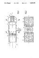
- FIG. 1 is a view in perspective of the device according to the invention.
- FIG. 2 is a view of the device according to the invention, taken along a longitudinal section.
- FIG. 3 is a view in section of the device according to the invention, taken along line III--III of FIG. 2.
- FIG. 4 is a view taken along a transverse section made along line IV--IV of FIG. 2.
- FIG. 1 shows a general view of a respiratory aid device adapted to be implanted in the trachea of a patient and comprising a tip 1 on which is mounted a unit 2 for filtration of the air flow.
- FIGS. 1 to 4 show tips 1 of tracheotomy cannulae, as well as filtration units 2, which present cylindrical cross sections. It is obvious that the cross sections of these two elements may present other geometrical shapes and the cross sections may in particular present square, diamond, hexagonal or rectangular shapes without departing from the scope of the invention.
- the tip 1, represented in FIG. 2, is generally implanted on the patient via a tracheotomy cannula 3 shown schematically in FIG. 2.
- a grip 5 for connection to an annexed oxygenation device is provided in the tip 1 and comprises a tubular connection proper and a bore through the wall of the tip 1.
- the tubular connection is preferably radial and perpendicular to the principal axis of the channel 4.
- the channel 4 preferably comprises at least one annular shoulder 6 formed downstream of the connection grip 5 with respect to the inhaled flow of air, of which the direction is represented by arrow A. These inner shoulders 6 are used as members for positioning elements intended to be positioned in the channel 4.
- the respiratory aid device comprises a phonation valve constituted by a support means 7 disposed in channel 4.
- the support means 7 is preferably a bush added and blocked in position in the channel 4 of the cannula against the annular shoulder 6.
- the bush comprises a transverse wall extending through the section of the channel 4.
- the wall thus defined is permeable to the inhaled and exhaled air flow and is preferably constituted by a series of cross pieces 8 constituting orifices for passage of the air flow.
- the cross pieces 8 join in a substantially central zone constituted by a ring 9.
- the thickness of the transverse wall of the support means 7, in the present case the bush, defines a downstream face 11 with respect to the inhaled air flow A, forming a support face for a non-return flap valve 12 mounted in sealed relationship against face 11.
- the shape of the non-return valve 12 is chosen such that it completely obstructs the channel 4 and is maintained in sealed abutment, preferably by a clip 13 engaged by force in the central part of the ring 9 and elastically blocked in the ring 9.
- the non-return flap valve 12 is chosen to be made of a flexible, elastic material, such as latex, siliconed or not, capable of presenting properties of distorsion from the fixing area defined by the fixed connection between the non-return valve 12 and the support means 7, namely the clip 13 and the ring 9.
- properties of distorsion include a radial distorsion from the fixing area and axial, i.e. in the direction of the inhaled air flow.
- the support face of the bush advantageously comprises at least two crosspieces 8, but that other equivalent means may also be employed such as, for example a grating assembly constituted by bars or an assembly provided with orifices of circular shape, for example. It can also be envisaged to produce the support and fixing area of the non-return valve on the bush in an eccentric area with respect to axis x--x' of the tip 1, even in an area located on the outer circumference of the bush. Of course, it can also be envisaged, more particularly in the last case mentioned, to provide a plurality of points of fixing of the non-return valve 12 on the bush 7.
- FIG. 2 also shows that the non-return valve 12 is preferably constituted by a series of undulations adapted to give it accentuated flexibility and elasticity.
- the end opposite that part of the tip 1 which is positioned on the tracheotomy cannula 3, is intended to receive a filtration unit 2 which, in the embodiments shown in FIGS. 1 and 3, is preferably constituted by two filtering elements 2a and 2b.
- the filtration unit 2 comprises an adapting tip 14, of section virtually identical to that of tip 1, in order to be able to be inserted by force and in sealed manner inside the channel 4 and to be blocked in position therein by means, for example, of systems of the jaw type.
- the adapting tip 14 extends by two diverging branches 2a and 2b which may be of cylindrical section, with longitudinal axes perpendicular to the axis x'x' of the tip 1, so as to give the filtration unit 2 the general form of a "T".
- the join between the two diverging branches 2a, 2b and the tip 14, is constituted by a transition zone 15 of which the cross section is of dimensions smaller than the cross section of each of the diverging branches 2a, 2b, to constitute a Venturi tube.
- the filtration elements are advantageously composed of filtering cartridges 16 introduced in each of the branches 2a, 2b and coming into abutment against the shoulders of each of the branches 2a, 2b resulting from the reduction in section of the zone of join 15. It can also be envisaged to provide a system for regulation of the Venturi effect with manual control.
- a filtration unit 2 provided with two diverging branches forming a "T"
- a filtration unit comprising one single branch located in line with tip 1
- the inhaled air is firstly filtered inside the cartridges 16, then is accelerated by the Venturi system formed by the reduction in section of the zone of join 15, to exert a pressure on the non-return valve 12 which then distorts radially and axially in the direction of the inhaled air flow A in order to allow the air flow to penetrate in the patient's larynx.
- the non-return valve 12 Upon exhalation of the air flow, the non-return valve 12 is applied in sealed manner against the support face of the bush and thus forms an obstacle to the passage of the air through the cannula 4, then enabling the patient to use the air imprisoned in the trachea to vibrate his/her vocal chords. If the state of the patient requires a forced oxygenation, the oxygen penetrates through the connection grip 5 and radially deforms the non-return valve 12, in the same manner as defined previously, and is then blocked inside the patient's larynx, enabling him to conserve the use of speech, even in a situation of forced oxygenation, the connection grip 5 lying upstream of the non-return valve 12 with respect to the inhaled air.
- a second annular shoulder 6a located downstream of the annular shoulder 6 adapted to receive the support means 7, in order to serve as seat for receiving a safety device constituted by a separation wall 17 of the channel 4 capable of preventing passage of the non-return valve 12 in the patient's trachea.
- the separation wall 17 advantageously consists in a disc rendered permeable to the air flow, by means of orifices provided in its thickness. Permeability of the wall 17 may be obtained by a crosspiece structure, similar to that described for the support face of the support means 7, or may consist in a grating or perforated structure.
- the device thus described enables a tracheotomized patient to conserve the use of his/her vocal chords, even in the case of forced oxygenation, thanks to the valve and to the oxygeno-phonation device proposed.
- Assembly of the non-return valve 12 on a support means 7 added inside the channel 4 allows, if necessary, an easy and rapid change of the phonation valve.
- the invention finds a preferred application in the production of tips of tracheotomy cannulae connected to forced oxygenation appliances in order to constitute oxygeno-phonation devices.
Landscapes
- Health & Medical Sciences (AREA)
- Pulmonology (AREA)
- Life Sciences & Earth Sciences (AREA)
- Animal Behavior & Ethology (AREA)
- Anesthesiology (AREA)
- Biomedical Technology (AREA)
- Heart & Thoracic Surgery (AREA)
- Hematology (AREA)
- Emergency Medicine (AREA)
- Engineering & Computer Science (AREA)
- General Health & Medical Sciences (AREA)
- Public Health (AREA)
- Veterinary Medicine (AREA)
- Respiratory Apparatuses And Protective Means (AREA)
- Prostheses (AREA)
- Infusion, Injection, And Reservoir Apparatuses (AREA)
Abstract
Description
Claims (11)
Applications Claiming Priority (2)
| Application Number | Priority Date | Filing Date | Title |
|---|---|---|---|
| FR8907625 | 1989-06-05 | ||
| FR8907625A FR2647680B1 (en) | 1989-06-05 | 1989-06-05 | OXYGENO-PHONATION VALVE AND TRACHEOTOMY CANNULA CAP COMPRISING SAID OXYGENO-PHONATION VALVE |
Publications (1)
| Publication Number | Publication Date |
|---|---|
| US5259378A true US5259378A (en) | 1993-11-09 |
Family
ID=9382539
Family Applications (1)
| Application Number | Title | Priority Date | Filing Date |
|---|---|---|---|
| US07/671,711 Expired - Lifetime US5259378A (en) | 1989-06-05 | 1990-06-01 | Phonation device for tracheotomy patients including a check valve and filtering means |
Country Status (8)
| Country | Link |
|---|---|
| US (1) | US5259378A (en) |
| EP (1) | EP0431108B1 (en) |
| AT (1) | ATE98134T1 (en) |
| DE (1) | DE69005086T2 (en) |
| DK (1) | DK0431108T3 (en) |
| ES (1) | ES2049034T3 (en) |
| FR (1) | FR2647680B1 (en) |
| WO (1) | WO1990014854A1 (en) |
Cited By (37)
| Publication number | Priority date | Publication date | Assignee | Title |
|---|---|---|---|---|
| WO1995017138A1 (en) * | 1993-12-23 | 1995-06-29 | Atos Medical Ab | Tracheostoma device |
| US5606966A (en) * | 1992-07-10 | 1997-03-04 | Kapitex Healthcare Ltd. | Tracheostomy tube assembly |
| US5840091A (en) * | 1995-07-13 | 1998-11-24 | Steve Culpepper | Smog and dust filter for a tracheostomy tube |
| US5950620A (en) * | 1998-06-29 | 1999-09-14 | Stricklin; Walter D. | Resuscitation device for use with stomas |
| WO2000021599A1 (en) | 1998-10-13 | 2000-04-20 | Mallinckrodt Inc. | Bi-functional in-line phonation valve |
| WO2000030708A1 (en) | 1998-11-23 | 2000-06-02 | Mallinckrodt Inc. | Phonation valve for breathing tube |
| US6422235B1 (en) * | 1998-05-14 | 2002-07-23 | Atos Medical Ab | Vocal valve with filter |
| US6439233B1 (en) * | 1999-02-01 | 2002-08-27 | ADEVA Medical Gesellschaft für Entwicklung und Vertrieb von Medizinischen Implantat-Artikeln mbH | Tracheal stoma valve |
| US20020156527A1 (en) * | 1999-06-04 | 2002-10-24 | Jan-Ove Persson | Tracheostoma valve |
| US6668831B1 (en) | 2001-02-20 | 2003-12-30 | Michael E. Hegwood | Appliance for a stoma |
| US6745766B2 (en) * | 2000-03-29 | 2004-06-08 | Mallinckrodt Holdings B.V. | Heat and moisture exchanger |
| US20050005941A1 (en) * | 2002-02-22 | 2005-01-13 | Bischoff Medical Devices, Llc | Decorative valved tracheostomy device |
| US7021314B1 (en) | 2004-07-19 | 2006-04-04 | Lane Charles J | Stoma stent with integrated speech flap valve |
| US20070251523A1 (en) * | 2003-12-16 | 2007-11-01 | Landuyt Christophe V | Gas-Treatment Devices |
| US20080072912A1 (en) * | 2005-03-09 | 2008-03-27 | Scott S D | Tracheostomy Appliances and Methods for the Treatment of Sleep Apnea Syndromes |
| DE202008007056U1 (en) | 2008-05-24 | 2008-07-31 | Neubauer, Norbert | Moist heat exchange device for the breathing air |
| DE202008011544U1 (en) | 2008-08-29 | 2008-10-30 | Neubauer, Norbert | Moist heat exchange device for the breathing air |
| US20090126724A1 (en) * | 2005-01-12 | 2009-05-21 | Infamed Limited | One-way valve |
| US20090194100A1 (en) * | 2005-08-26 | 2009-08-06 | National University Corporation Okayama University | Nostril plug for improving articulatory disorder |
| DE202012001825U1 (en) | 2012-02-22 | 2012-04-03 | Norbert Neubauer | Moist heat exchanger for the breathing air |
| DE202012003723U1 (en) | 2012-04-12 | 2012-05-23 | Norbert Neubauer | Moist heat exchanger for the breathing air |
| DE202012004539U1 (en) | 2012-05-08 | 2012-06-15 | Norbert Neubauer | Moist heat exchanger for the breathing air |
| DE202012005851U1 (en) | 2012-06-14 | 2012-07-10 | Norbert Neubauer | Moist heat exchanger for the breathing air |
| DE202012008906U1 (en) | 2012-09-14 | 2012-10-25 | Norbert Neubauer | Moisture heat exchanger for breathing air |
| DE202012011449U1 (en) | 2012-11-28 | 2013-01-09 | Norbert Neubauer | Moist heat exchange device for the breathing air |
| DE202012011324U1 (en) | 2012-11-24 | 2013-01-18 | Norbert Neubauer | Moist heat exchange device for the breathing air |
| DE202013001950U1 (en) | 2013-02-28 | 2013-03-27 | Norbert Neubauer | Moist heat exchange device for the breathing air |
| US20150013684A1 (en) * | 2013-07-11 | 2015-01-15 | Covidien Lp | Speaking valve system with cuff deflation |
| USD747463S1 (en) * | 2007-07-30 | 2016-01-12 | Passy-Muir, Inc. | Tracheostomy valve |
| US9981100B2 (en) | 2007-07-30 | 2018-05-29 | Passy-Muir, Inc. | Tracheostomy valves and related methods |
| KR101955699B1 (en) * | 2018-09-20 | 2019-03-08 | 김옥련 | Device for assisting vocalization of Tracheostomy tube |
| US10532171B2 (en) | 2014-09-30 | 2020-01-14 | Frank H. Arlinghaus, Jr. | Tracheostomy or endotracheal tube adapter for speech |
| WO2021245368A1 (en) * | 2020-06-03 | 2021-12-09 | Smiths Medical International Limited | Medico-surgical apparatus |
| KR102351251B1 (en) * | 2020-07-28 | 2022-01-14 | 김효종 | Device for assisting vocalization of tracheostomy tube |
| KR20220032251A (en) * | 2020-09-07 | 2022-03-15 | 가톨릭대학교 산학협력단 | Mask for tracheostomy tube |
| US11285287B2 (en) | 2014-09-30 | 2022-03-29 | Frank H. Arlinghaus, Jr. | Tracheostomy or endotracheal tube adapter for speech |
| CN115105703A (en) * | 2022-07-20 | 2022-09-27 | 广东益德医疗科技有限公司 | Sound conversion head for medical tracheostomy tube |
Families Citing this family (3)
| Publication number | Priority date | Publication date | Assignee | Title |
|---|---|---|---|---|
| SE9502354L (en) * | 1995-06-28 | 1996-12-29 | Respaid Ab | Respiratory Aids |
| US5806515A (en) * | 1997-03-28 | 1998-09-15 | Passy-Muir, Inc. | Supplemental oxygen adapter for tracheostomy speaking valves |
| DE19900712C1 (en) * | 1998-09-23 | 2000-08-03 | Adeva Medical Ges Fuer Entwick | Tracheostoma valve |
Citations (10)
| Publication number | Priority date | Publication date | Assignee | Title |
|---|---|---|---|---|
| US3683931A (en) * | 1970-04-16 | 1972-08-15 | Paramedical Specialties | Tracheal instrument |
| US4040428A (en) * | 1976-08-30 | 1977-08-09 | The Aro Corporation | Control valves for tracheotomy patient or laryngeal prosthesis |
| US4202330A (en) * | 1978-06-26 | 1980-05-13 | Jariabka Daniel S | Life support system and valve for use therewith |
| US4325366A (en) * | 1980-07-07 | 1982-04-20 | Tabor Carl J | Valve and method for use with a tracheotomy tube |
| FR2559067A1 (en) * | 1984-02-06 | 1985-08-09 | Fixfabriken Ab | TRACHEOTOMY VALVE |
| US4582058A (en) * | 1984-11-26 | 1986-04-15 | Bivona, Inc. | Tracheostoma valves |
| DE8701414U1 (en) * | 1987-01-29 | 1987-04-16 | Passy & Passy, Inc., Irvine, Ca. | Tracheostomy tube |
| US4759356A (en) * | 1985-03-08 | 1988-07-26 | David Muir | Tracheostomy device and related methods |
| US4971054A (en) * | 1988-01-22 | 1990-11-20 | Respaid Ab | Breathing valve |
| US5042468A (en) * | 1989-02-13 | 1991-08-27 | Gibeck Respiration Ab | Breathing device |
-
1989
- 1989-06-05 FR FR8907625A patent/FR2647680B1/en not_active Expired - Lifetime
-
1990
- 1990-06-01 US US07/671,711 patent/US5259378A/en not_active Expired - Lifetime
- 1990-06-01 EP EP90908562A patent/EP0431108B1/en not_active Revoked
- 1990-06-01 AT AT90908562T patent/ATE98134T1/en not_active IP Right Cessation
- 1990-06-01 DK DK90908562.3T patent/DK0431108T3/en active
- 1990-06-01 DE DE69005086T patent/DE69005086T2/en not_active Revoked
- 1990-06-01 ES ES90908562T patent/ES2049034T3/en not_active Expired - Lifetime
- 1990-06-01 WO PCT/FR1990/000382 patent/WO1990014854A1/en not_active Ceased
Patent Citations (11)
| Publication number | Priority date | Publication date | Assignee | Title |
|---|---|---|---|---|
| US3683931A (en) * | 1970-04-16 | 1972-08-15 | Paramedical Specialties | Tracheal instrument |
| US4040428A (en) * | 1976-08-30 | 1977-08-09 | The Aro Corporation | Control valves for tracheotomy patient or laryngeal prosthesis |
| US4202330A (en) * | 1978-06-26 | 1980-05-13 | Jariabka Daniel S | Life support system and valve for use therewith |
| US4325366A (en) * | 1980-07-07 | 1982-04-20 | Tabor Carl J | Valve and method for use with a tracheotomy tube |
| FR2559067A1 (en) * | 1984-02-06 | 1985-08-09 | Fixfabriken Ab | TRACHEOTOMY VALVE |
| US4538607A (en) * | 1984-02-06 | 1985-09-03 | Ab Fixfabriken | Tracheostomy valve |
| US4582058A (en) * | 1984-11-26 | 1986-04-15 | Bivona, Inc. | Tracheostoma valves |
| US4759356A (en) * | 1985-03-08 | 1988-07-26 | David Muir | Tracheostomy device and related methods |
| DE8701414U1 (en) * | 1987-01-29 | 1987-04-16 | Passy & Passy, Inc., Irvine, Ca. | Tracheostomy tube |
| US4971054A (en) * | 1988-01-22 | 1990-11-20 | Respaid Ab | Breathing valve |
| US5042468A (en) * | 1989-02-13 | 1991-08-27 | Gibeck Respiration Ab | Breathing device |
Cited By (47)
| Publication number | Priority date | Publication date | Assignee | Title |
|---|---|---|---|---|
| US5606966A (en) * | 1992-07-10 | 1997-03-04 | Kapitex Healthcare Ltd. | Tracheostomy tube assembly |
| WO1995017138A1 (en) * | 1993-12-23 | 1995-06-29 | Atos Medical Ab | Tracheostoma device |
| US5738095A (en) * | 1993-12-23 | 1998-04-14 | Atos Medical Ab | Tracheostoma device |
| US5840091A (en) * | 1995-07-13 | 1998-11-24 | Steve Culpepper | Smog and dust filter for a tracheostomy tube |
| US6422235B1 (en) * | 1998-05-14 | 2002-07-23 | Atos Medical Ab | Vocal valve with filter |
| US5950620A (en) * | 1998-06-29 | 1999-09-14 | Stricklin; Walter D. | Resuscitation device for use with stomas |
| WO2000021599A1 (en) | 1998-10-13 | 2000-04-20 | Mallinckrodt Inc. | Bi-functional in-line phonation valve |
| US6189534B1 (en) | 1998-10-13 | 2001-02-20 | Mallinckrodt Inc. | Bi-functional in-line phonation valve |
| US6386200B1 (en) * | 1998-10-13 | 2002-05-14 | Mallinckrodt Inc. | Bi-functional in-line phonation valve |
| WO2000030708A1 (en) | 1998-11-23 | 2000-06-02 | Mallinckrodt Inc. | Phonation valve for breathing tube |
| US6334441B1 (en) | 1998-11-23 | 2002-01-01 | Mallinckrodt Medical, Inc. | Phonation valve for breathing tube |
| US6439233B1 (en) * | 1999-02-01 | 2002-08-27 | ADEVA Medical Gesellschaft für Entwicklung und Vertrieb von Medizinischen Implantat-Artikeln mbH | Tracheal stoma valve |
| US20020156527A1 (en) * | 1999-06-04 | 2002-10-24 | Jan-Ove Persson | Tracheostoma valve |
| US6921417B2 (en) * | 1999-06-04 | 2005-07-26 | Atos Medical Ab | Tracheostoma valve |
| US6745766B2 (en) * | 2000-03-29 | 2004-06-08 | Mallinckrodt Holdings B.V. | Heat and moisture exchanger |
| US20040216739A1 (en) * | 2000-03-29 | 2004-11-04 | Massimo Fini | Heat and moisture exchanger |
| US6968841B2 (en) * | 2000-03-29 | 2005-11-29 | Mallinckrodt Holdings B.V. | Heat and moisture exchanger |
| US6668831B1 (en) | 2001-02-20 | 2003-12-30 | Michael E. Hegwood | Appliance for a stoma |
| US20050005941A1 (en) * | 2002-02-22 | 2005-01-13 | Bischoff Medical Devices, Llc | Decorative valved tracheostomy device |
| US20070251523A1 (en) * | 2003-12-16 | 2007-11-01 | Landuyt Christophe V | Gas-Treatment Devices |
| US7021314B1 (en) | 2004-07-19 | 2006-04-04 | Lane Charles J | Stoma stent with integrated speech flap valve |
| US20090126724A1 (en) * | 2005-01-12 | 2009-05-21 | Infamed Limited | One-way valve |
| US20080072912A1 (en) * | 2005-03-09 | 2008-03-27 | Scott S D | Tracheostomy Appliances and Methods for the Treatment of Sleep Apnea Syndromes |
| US8800564B2 (en) | 2005-03-09 | 2014-08-12 | Elaine D. Scott | Tracheostomy appliances and methods for the treatment of sleep apnea syndromes |
| US20090194100A1 (en) * | 2005-08-26 | 2009-08-06 | National University Corporation Okayama University | Nostril plug for improving articulatory disorder |
| US9981100B2 (en) | 2007-07-30 | 2018-05-29 | Passy-Muir, Inc. | Tracheostomy valves and related methods |
| USD747463S1 (en) * | 2007-07-30 | 2016-01-12 | Passy-Muir, Inc. | Tracheostomy valve |
| DE202008007056U1 (en) | 2008-05-24 | 2008-07-31 | Neubauer, Norbert | Moist heat exchange device for the breathing air |
| DE202008011544U1 (en) | 2008-08-29 | 2008-10-30 | Neubauer, Norbert | Moist heat exchange device for the breathing air |
| DE202012001825U1 (en) | 2012-02-22 | 2012-04-03 | Norbert Neubauer | Moist heat exchanger for the breathing air |
| DE202012003723U1 (en) | 2012-04-12 | 2012-05-23 | Norbert Neubauer | Moist heat exchanger for the breathing air |
| DE202012004539U1 (en) | 2012-05-08 | 2012-06-15 | Norbert Neubauer | Moist heat exchanger for the breathing air |
| DE202012005851U1 (en) | 2012-06-14 | 2012-07-10 | Norbert Neubauer | Moist heat exchanger for the breathing air |
| DE202012008906U1 (en) | 2012-09-14 | 2012-10-25 | Norbert Neubauer | Moisture heat exchanger for breathing air |
| DE202012011324U1 (en) | 2012-11-24 | 2013-01-18 | Norbert Neubauer | Moist heat exchange device for the breathing air |
| DE202012011449U1 (en) | 2012-11-28 | 2013-01-09 | Norbert Neubauer | Moist heat exchange device for the breathing air |
| DE202013001950U1 (en) | 2013-02-28 | 2013-03-27 | Norbert Neubauer | Moist heat exchange device for the breathing air |
| US20150013684A1 (en) * | 2013-07-11 | 2015-01-15 | Covidien Lp | Speaking valve system with cuff deflation |
| US10532171B2 (en) | 2014-09-30 | 2020-01-14 | Frank H. Arlinghaus, Jr. | Tracheostomy or endotracheal tube adapter for speech |
| US11285287B2 (en) | 2014-09-30 | 2022-03-29 | Frank H. Arlinghaus, Jr. | Tracheostomy or endotracheal tube adapter for speech |
| KR101955699B1 (en) * | 2018-09-20 | 2019-03-08 | 김옥련 | Device for assisting vocalization of Tracheostomy tube |
| WO2021245368A1 (en) * | 2020-06-03 | 2021-12-09 | Smiths Medical International Limited | Medico-surgical apparatus |
| US20230191060A1 (en) * | 2020-06-03 | 2023-06-22 | Smiths Medical International Limited | Medico-surgical apparatus |
| KR102351251B1 (en) * | 2020-07-28 | 2022-01-14 | 김효종 | Device for assisting vocalization of tracheostomy tube |
| KR20220032251A (en) * | 2020-09-07 | 2022-03-15 | 가톨릭대학교 산학협력단 | Mask for tracheostomy tube |
| KR20220086539A (en) * | 2020-09-07 | 2022-06-23 | 가톨릭대학교 산학협력단 | Mask frame unit for tracheostomy tube |
| CN115105703A (en) * | 2022-07-20 | 2022-09-27 | 广东益德医疗科技有限公司 | Sound conversion head for medical tracheostomy tube |
Also Published As
| Publication number | Publication date |
|---|---|
| DE69005086D1 (en) | 1994-01-20 |
| ES2049034T3 (en) | 1994-04-01 |
| FR2647680B1 (en) | 1996-03-08 |
| EP0431108B1 (en) | 1993-12-08 |
| WO1990014854A1 (en) | 1990-12-13 |
| ATE98134T1 (en) | 1993-12-15 |
| DE69005086T2 (en) | 1994-06-01 |
| DK0431108T3 (en) | 1994-04-18 |
| EP0431108A1 (en) | 1991-06-12 |
| FR2647680A1 (en) | 1990-12-07 |
Similar Documents
| Publication | Publication Date | Title |
|---|---|---|
| US5259378A (en) | Phonation device for tracheotomy patients including a check valve and filtering means | |
| US6997177B2 (en) | Ventilation interface for sleep apnea therapy | |
| DE60113702T2 (en) | Respiratory mask with porous venting membrane | |
| JP3687981B2 (en) | Mask and vent assembly therefor | |
| US8127767B2 (en) | Device for delivering respiratory gas directly into the nose of a user | |
| US8826910B2 (en) | Mask and vent assembly therefor | |
| DE19817332C2 (en) | oxygen mask | |
| US5117820A (en) | Intra-nasal filter | |
| AU2014336976B2 (en) | Improved oxygenating apparatus | |
| US9327092B2 (en) | Ventilation mask with integrated piloted exhalation valve | |
| US4261355A (en) | Constant positive pressure breathing apparatus | |
| US20160008565A1 (en) | Ventilation interface for sleep apnea therapy | |
| WO1995017220A1 (en) | A device for the supply of oxygen and/or other gases to a patient | |
| JP2008526275A (en) | Respirator with a gas washout vent and a gas washout vent assembly for a respirator | |
| US20240139459A1 (en) | Connectors for respiratory system components, a filter, and a respiratory conduit end cap | |
| EP3551267B1 (en) | Heat and moisture exchanger | |
| EP2295102B1 (en) | Breathing mask assembly with a breathing gas discharge device | |
| WO2014138125A1 (en) | Ventilation mask with integrated piloted exhalation valve | |
| US20060096597A1 (en) | Swivel filter for use with sleep apnea and other respiratory equipment including associated interface systems | |
| US6484723B2 (en) | Tracheostomy air filtration system | |
| EP1317941B1 (en) | Nasal ventilation cannula | |
| WO2014025591A1 (en) | Ventilation mask with integrated piloted exhalation valve | |
| EP1747792B1 (en) | Heat and moisture exchanger with speaking function | |
| WO2005058401A1 (en) | Device for insertion into the trachea or between the trachea and the esophagus | |
| AU781624B2 (en) | Ventilation interface for sleep apnea therapy |
Legal Events
| Date | Code | Title | Description |
|---|---|---|---|
| AS | Assignment |
Owner name: HUCHON, JEAN-MICHEL, FRANCE Free format text: ASSIGNMENT OF ASSIGNORS INTEREST;ASSIGNOR:VANNSON, PHILIPPE;REEL/FRAME:006986/0439 Effective date: 19940331 |
|
| AS | Assignment |
Owner name: HUCHON, JEAN-MICHAEL, FRANCE Free format text: CORRECTION OF ADDRESSEE'S ADDRESS ON DOCUMENT RECORDED ON REEL 6986 FRAME 439;ASSIGNOR:VANNSON, PHILIPPE;REEL/FRAME:007662/0967 Effective date: 19940331 |
|
| AS | Assignment |
Owner name: HUCHON, JEAN-MICHEL, FRANCE Free format text: RECORD TO CORRECT ASSIGNEE'S ADDRESS PREVIOUSLY RECORDED ON REEL 6986 FRAME 439;ASSIGNOR:VANNSON, PHILIPPE;REEL/FRAME:007562/0229 Effective date: 19940331 |
|
| FEPP | Fee payment procedure |
Free format text: PAYOR NUMBER ASSIGNED (ORIGINAL EVENT CODE: ASPN); ENTITY STATUS OF PATENT OWNER: SMALL ENTITY |
|
| FPAY | Fee payment |
Year of fee payment: 4 |
|
| REMI | Maintenance fee reminder mailed | ||
| FEPP | Fee payment procedure |
Free format text: PETITION RELATED TO MAINTENANCE FEES FILED (ORIGINAL EVENT CODE: PMFP); ENTITY STATUS OF PATENT OWNER: SMALL ENTITY |
|
| FEPP | Fee payment procedure |
Free format text: PETITION RELATED TO MAINTENANCE FEES GRANTED (ORIGINAL EVENT CODE: PMFG); ENTITY STATUS OF PATENT OWNER: SMALL ENTITY |
|
| FP | Lapsed due to failure to pay maintenance fee |
Effective date: 20011109 |
|
| FPAY | Fee payment |
Year of fee payment: 8 |
|
| STCF | Information on status: patent grant |
Free format text: PATENTED CASE |
|
| SULP | Surcharge for late payment | ||
| PRDP | Patent reinstated due to the acceptance of a late maintenance fee |
Effective date: 20020401 |
|
| AS | Assignment |
Owner name: FINECOR, SWITZERLAND Free format text: ASSIGNMENT OF ASSIGNORS INTEREST;ASSIGNOR:HUCHON, JEAN-MICHEL;REEL/FRAME:013056/0195 Effective date: 20020707 |
|
| REMI | Maintenance fee reminder mailed | ||
| FPAY | Fee payment |
Year of fee payment: 12 |
|
| SULP | Surcharge for late payment |
Year of fee payment: 11 |