US5259037A - Automated video imagery database generation using photogrammetry - Google Patents
Automated video imagery database generation using photogrammetry Download PDFInfo
- Publication number
- US5259037A US5259037A US07/651,819 US65181991A US5259037A US 5259037 A US5259037 A US 5259037A US 65181991 A US65181991 A US 65181991A US 5259037 A US5259037 A US 5259037A
- Authority
- US
- United States
- Prior art keywords
- frame
- data
- frames
- imagery
- forward looking
- Prior art date
- Legal status (The legal status is an assumption and is not a legal conclusion. Google has not performed a legal analysis and makes no representation as to the accuracy of the status listed.)
- Expired - Lifetime
Links
Images
Classifications
-
- G—PHYSICS
- G09—EDUCATION; CRYPTOGRAPHY; DISPLAY; ADVERTISING; SEALS
- G09B—EDUCATIONAL OR DEMONSTRATION APPLIANCES; APPLIANCES FOR TEACHING, OR COMMUNICATING WITH, THE BLIND, DEAF OR MUTE; MODELS; PLANETARIA; GLOBES; MAPS; DIAGRAMS
- G09B29/00—Maps; Plans; Charts; Diagrams, e.g. route diagram
- G09B29/003—Maps
-
- G—PHYSICS
- G01—MEASURING; TESTING
- G01C—MEASURING DISTANCES, LEVELS OR BEARINGS; SURVEYING; NAVIGATION; GYROSCOPIC INSTRUMENTS; PHOTOGRAMMETRY OR VIDEOGRAMMETRY
- G01C11/00—Photogrammetry or videogrammetry, e.g. stereogrammetry; Photographic surveying
- G01C11/02—Picture taking arrangements specially adapted for photogrammetry or photographic surveying, e.g. controlling overlapping of pictures
-
- G—PHYSICS
- G06—COMPUTING OR CALCULATING; COUNTING
- G06T—IMAGE DATA PROCESSING OR GENERATION, IN GENERAL
- G06T15/00—Three-dimensional [3D] image rendering
- G06T15/10—Geometric effects
-
- G—PHYSICS
- G09—EDUCATION; CRYPTOGRAPHY; DISPLAY; ADVERTISING; SEALS
- G09B—EDUCATIONAL OR DEMONSTRATION APPLIANCES; APPLIANCES FOR TEACHING, OR COMMUNICATING WITH, THE BLIND, DEAF OR MUTE; MODELS; PLANETARIA; GLOBES; MAPS; DIAGRAMS
- G09B9/00—Simulators for teaching or training purposes
- G09B9/02—Simulators for teaching or training purposes for teaching control of vehicles or other craft
- G09B9/08—Simulators for teaching or training purposes for teaching control of vehicles or other craft for teaching control of aircraft, e.g. Link trainer
- G09B9/30—Simulation of view from aircraft
- G09B9/301—Simulation of view from aircraft by computer-processed or -generated image
-
- H—ELECTRICITY
- H04—ELECTRIC COMMUNICATION TECHNIQUE
- H04N—PICTORIAL COMMUNICATION, e.g. TELEVISION
- H04N13/00—Stereoscopic video systems; Multi-view video systems; Details thereof
- H04N13/20—Image signal generators
- H04N13/261—Image signal generators with monoscopic-to-stereoscopic image conversion
-
- H—ELECTRICITY
- H04—ELECTRIC COMMUNICATION TECHNIQUE
- H04N—PICTORIAL COMMUNICATION, e.g. TELEVISION
- H04N13/00—Stereoscopic video systems; Multi-view video systems; Details thereof
- H04N2013/0074—Stereoscopic image analysis
- H04N2013/0081—Depth or disparity estimation from stereoscopic image signals
Definitions
- the present invention relates to the field of photogrammetry, and, more particularly, to a method for automatically generating a three-dimensional video imagery photographic database.
- An image generation system such as the Computer Generated Synthesized Imagery (CGSI) system requires a video imagery database in order to generate realtime perspective images for use in simulators such as simulated flight trainers.
- video imagery databases have been generated by taking downlooking aerial photographs, developing the film, assembling and registering the photographs into a mosaic pattern encompassing the terrain of interest, digitizing the photographs, performing radiometric balancing, and performing orthorectification by registering the photographs to elevation data such as that provided by the Defense Mapping Agency.
- photographic visual databases require a large expenditure of time and money.
- photographic data is typically not up-to-date. Frequently, no elevation data exists for the terrain of interest, no photography of the area exists, and no stereo pair imagery exists.
- an aircraft flies over known ground features used as ground control points.
- Pictures are taken of the ground from an oblique point of view using a camera such as a motion picture camera or a videocamera.
- the film is processed to obtain digitized photographs which are fed directly into an automatic database generating computer. No attempt is made at registration, radiometric balancing, orthorectification, or making a mosaic of multiple images.
- the method of the present invention is less time-consuming and labor intensive than conventional techniques employing downlooking photographs.
- the method of the present invention uses less manual intervention and generates databases in a shorter period of time, from data acquisition through database completion.
- the automatic database generating computer calculates the position of the aircraft for each frame based on known ground control points on maps of the terrain. On overlapping areas of common coverage in adjacent frames, the position of the aircraft is calculated to the same ground feature from the displaced camera positions. This process is continued with other additional points or ground features until about 20 common points have been calculated for adjacent frames. In addition to making calculations from frame-to-frame, the computer also skips over some frames and makes calculations of position from about every sixth frame. In this manner, the calculations are continually refined.
- the automatic database generating computer makes use of modern extended Kalman filtering techniques to provide optimal estimates of the position and attitude of the aircraft with respect to each frame of imagery. This provides a continuous smooth determination of the orientation of the camera at the moment of exposure of each frame.
- the Kalman filter estimation of the vehicle position and attitude is made with respect to six degrees of freedom: x, y, z and roll, pitch and yaw.
- the automatic database generating computer uses a correlation filter to determine corresponding pixels in adjacent frames. The computer calculates range to these corresponding pixel surfaces from the displaced camera positions, and determines the x, y and z position.
- the elevation data and radiometric data for each pixel is determined. The radiometric data is extracted only from the lower portion of each frame because it is closer to the camera.
- the radiometric data for each pixel is given in terms of eight digital bits which represent 256 elements of information.
- the imagery is warped onto the elevation data to generate a top down view.
- the resulting database is used in image generation systems such as the CGSI system to generate perspective images for use in simulators.
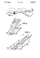
- FIG. 1 shows an aircraft taking oblique aerial photographs as it flys over terrain of interest
- FIG. 2 is a diagram illustrating the geometric principle of stereophotogrammetry
- FIG. 3 is a diagram illustrating the geometric principle employed in the method of the present invention for generating a downlooking three-dimensional database from oblique sequential imagery.
- FIG. 1 shows an aircraft 10 flying along a flight path 11 over undulating terrain 12 including a building 13.
- a camera 14 taking sequential aerial photographs of the terrain 12.
- the camera 14 has an oblique field of view as indicated by two lines 15, 16 in FIG. 1.
- the camera 14 may be a video camera or a motion picture camera, or the like, which produces a sequence of frames of imagery along the flight path 11. There are substantial areas of overlap between adjacent frames of imagery in the sequence. It will be understood that a single camera 14 is used to make the sequence of frames of imagery.
- Stereo pairs of cameras are not used, although as will be pointed out hereinafter, modified principles of stereo pair photogrammetry are used to process data derived from the sequence of frames of imagery.
- FIG. 2 there is shown a diagram illustrating the geometric principle of stereophotogrammetry. It should be clearly understood that each image point on a photograph corresponds to a unique point in the object scene. A geometric relationship exists between image points in a two-dimensional photograph and corresponding locations in three-dimensional object space. There exists a method in the field of mathematics that solves the problem of stereoscopic pairs of downlooking photographs that are taken at the same time from slightly different vantage points.
- a surface area 20 is photographed from two different camera positions 21, 22.
- An area of common coverage 23 by the two photographs is called stereoscopic overlap.
- Photographic films at the two different camera positions 21, 22 record the imagery of the surface area 20 being photographed.
- a plurality of lines 26 represent light rays that extend from discrete points 27 on the surface area 20 to the camera positions 21, 22. Photographs 24, 25 made from the film are shown in FIG. 2 having the plurality of lines 26 passing therethrough.
- Each of the photographs 24, 25 may be considered as a record of the bundle of light rays which travel from object space, pass through a lens system and register on photographic film.
- an optical model of the stereoscopic overlap area of common coverage 23 is constructed in an instrument known as a stereoplotter which comprises two projectors. Each bundle of rays is reconstructed by inserting either a glass plate diapositive or film negative into one of the projectors. The two projectors are translated and tilted until they assume the same relative position and attitude as when the photographs were taken in the two camera positions 21, 22. When the projectors have been properly positioned, corresponding light rays in the two bundles intersect in space and a three-dimensional optical model is formed.
- control points points of known ground positions are used to scale the model and to level it with respect to the reference plane in the stereoplotter. Once orientation is completed, the position of any point in the stereo model may be measured at the intersection of the two corresponding rays from the two projectors.
- a mathematical expression which is a function of the position of a point in the object space, position of the corresponding image point in the photograph, position of the exposure center in the ground reference system, direction of the optical axis of the camera and the perspective geometry of the camera. If the perspective geometry of the camera has been determined by camera calibration, and if three or more control points are imaged on a photograph, the position of the camera and its attitude with respect to the ground control reference system can be determined. Once the orientation of both of the photographs 24, 25 of a stereoscopic pair is known, the position of any object point which is located in the overlap area of common coverage 23 may be computed as the point of intersection of two rays.
- FIG. 3 there is shown a diagram illustrating the method of the present invention for generating a downlooking three-dimensional database from oblique sequential imagery.
- FIG. 3 generally corresponds to FIG. 2 in that the surface area 20 being photographed is the same.
- FIG. 3 also corresponds to FIG. 1 in that a vehicle traveling along a flight path 40 is taking sequential aerial photographs at two camera positions 41, 42 and with an oblique field of view.
- a plurality of lines 43 represent light rays that extend from the discrete points 27 on the surface area 20 to the camera positions 41, 42.
- the area of common coverage 23 that was seen in FIG. 2 also exists in FIG. 3 because the oblique field photographs are taken from slightly different vantage points at slightly different instants of time.
- a modified mathematical technique or method of stereo pairs is employed to automatically generate terrain elevation data, and to generate a downlooking database from the oblique sequential imagery.
- the aircraft 10 flies over a known path 11 having known ground features that are used as ground control points. Corresponding maps are available giving the location and altitude of these ground control points. If available for the terrain of interest, data from the Defense Mapping Agency may be used to establish the initial coarse resolution x, y, z location data. None needs to be done aboard the aircraft 10 except fly the preselected flight path 11 and aim the camera 14 along the oblique field of view indicated by the two lines 15, 16. Typically, the camera 14 takes pictures at the rate of thirty frames per second so that for a half hour flight 54,000 frames of photographs will have been made.
- the film is removed from the camera 14 and processed. If the camera 14 is a motion picture camera, the film is processed using chemical processes and the frames are digitized. If the camera 14 is a video camera, the video signal is processed to obtain digitized photographs. It is possible to use a camera 14 that produces a digitized signal directly and that does not require any intermediate processing. Database generation from digital video or video tape does not require film processing nor film digitization. Once the sequential oblique digitized imagery is available, it is fed directly into an automatic database generating computer. No attempt is made at registration, radiometric balancing, orthorectification, or making a mosaic of multiple images. Thus, the technique of the present invention is less time-consuming and labor intensive than conventional techniques employing downlooking photographs. The method of the present invention uses less manual intervention and generates databases in a shorter period of time, from data acquisition through database completion.
- the automatic database generating computer calculates the position of the aircraft 10 for each frame based on known ground control points on maps of the terrain. On the overlapping area of common coverage 23 in adjacent frames, the position of the aircraft 10 is calculated to the same ground feature from the displaced camera positions 41, 42. This process is continued with other additional points or ground features until about 20 common points have been calculated for adjacent frames. In addition to making calculations from frame-to-frame, the computer also skips over some frames and makes calculations of position from about every sixth frame. In this manner, the calculations are continually refined.
- the automatic database generating computer makes use of modern extended Kalman filtering techniques to provide optimal estimates of the position and attitude of the aircraft 10 with respect to each frame of imagery. This provides a continuous smooth determination of the orientation of the camera at the moment of exposure of each frame.
- the Kalman filter estimation of the vehicle position and attitude is made with respect to six degrees of freedom: x, y, z and roll, pitch and yaw.
- the automatic database generating computer makes use of a correlation filter to determine corresponding pixels in adjacent frames.
- the computer calculates range to these corresponding pixel surfaces from the displaced camera positions 41, 42, and determines the x, y and z position.
- the mathematics involved is a modified version of the existing mathematics used in the field of photogrammetry to solve the similar problem of stereo pairs. This was discussed above in connection with FIG. 2.
- the elevation data and radiometric data for each pixel is determined.
- the radiometric data is extracted only from the lower portion of each frame because it is closer to the camera. Referring to FIG. 1, note that the foreground line 16 is shorter than the background line 15.
- the radiometric data for each pixel is given in terms of eight digital bits which represent 256 elements of information. This may be in terms of red, blue, green colors or in levels of black and white gray scale.
- the imagery is warped onto the elevation data to generate a top down view.
- This database is then used in an image generation system such as the CGSI system to generate realtime perspective images for simulation.
- the database made in accordance with the present invention provides a view of the sides of buildings, which is unique. When the conventional downlooking database is warped to get an oblique view, only an image of a warped roof is obtained, rather than an image of the side of the building.
Landscapes
- Engineering & Computer Science (AREA)
- Physics & Mathematics (AREA)
- Theoretical Computer Science (AREA)
- General Physics & Mathematics (AREA)
- Educational Administration (AREA)
- Educational Technology (AREA)
- Multimedia (AREA)
- Business, Economics & Management (AREA)
- Aviation & Aerospace Engineering (AREA)
- Geometry (AREA)
- Computer Hardware Design (AREA)
- Computer Graphics (AREA)
- Mathematical Physics (AREA)
- Radar, Positioning & Navigation (AREA)
- Remote Sensing (AREA)
- Signal Processing (AREA)
- Image Processing (AREA)
- Testing, Inspecting, Measuring Of Stereoscopic Televisions And Televisions (AREA)
- Image Analysis (AREA)
Abstract
Description
Claims (10)
Priority Applications (5)
| Application Number | Priority Date | Filing Date | Title |
|---|---|---|---|
| US07/651,819 US5259037A (en) | 1991-02-07 | 1991-02-07 | Automated video imagery database generation using photogrammetry |
| IL10052691A IL100526A (en) | 1991-02-07 | 1991-12-26 | Automated video imagery database generation using photogrammetry |
| CA002058877A CA2058877A1 (en) | 1991-02-07 | 1992-01-07 | Automated video imagery database generation using photogrammetry |
| EP19920300529 EP0498542A3 (en) | 1991-02-07 | 1992-01-22 | Automated video imagery database generation using photogrammetry |
| JP4022864A JPH0554128A (en) | 1991-02-07 | 1992-02-07 | Formation of automatic video image database using photograph ic measurement |
Applications Claiming Priority (1)
| Application Number | Priority Date | Filing Date | Title |
|---|---|---|---|
| US07/651,819 US5259037A (en) | 1991-02-07 | 1991-02-07 | Automated video imagery database generation using photogrammetry |
Publications (1)
| Publication Number | Publication Date |
|---|---|
| US5259037A true US5259037A (en) | 1993-11-02 |
Family
ID=24614355
Family Applications (1)
| Application Number | Title | Priority Date | Filing Date |
|---|---|---|---|
| US07/651,819 Expired - Lifetime US5259037A (en) | 1991-02-07 | 1991-02-07 | Automated video imagery database generation using photogrammetry |
Country Status (5)
| Country | Link |
|---|---|
| US (1) | US5259037A (en) |
| EP (1) | EP0498542A3 (en) |
| JP (1) | JPH0554128A (en) |
| CA (1) | CA2058877A1 (en) |
| IL (1) | IL100526A (en) |
Cited By (66)
| Publication number | Priority date | Publication date | Assignee | Title |
|---|---|---|---|---|
| US5530774A (en) * | 1994-03-25 | 1996-06-25 | Eastman Kodak Company | Generation of depth image through interpolation and extrapolation of intermediate images derived from stereo image pair using disparity vector fields |
| US5598359A (en) * | 1993-10-29 | 1997-01-28 | Southwest Research Institute | Weather effects generator for simulation systems |
| US5638116A (en) * | 1993-09-08 | 1997-06-10 | Sumitomo Electric Industries, Ltd. | Object recognition apparatus and method |
| WO1997036147A1 (en) * | 1996-03-28 | 1997-10-02 | Synthonics Incorporated | Methods and apparatus for using image data to determine camera location and orientation |
| US5692062A (en) * | 1994-10-03 | 1997-11-25 | Recon/Optical, Inc. | Electro-optical imaging array with profiled foward motion compensation |
| US5699444A (en) * | 1995-03-31 | 1997-12-16 | Synthonics Incorporated | Methods and apparatus for using image data to determine camera location and orientation |
| US5850469A (en) * | 1996-07-09 | 1998-12-15 | General Electric Company | Real time tracking of camera pose |
| US5850289A (en) * | 1994-08-24 | 1998-12-15 | Tricorder Technology Plc | Scanning arrangement and method |
| EP0930583A1 (en) * | 1998-01-16 | 1999-07-21 | Xerox Corporation | Image recording apparatus and method using light fields to track position and orientation |
| US5991437A (en) * | 1996-07-12 | 1999-11-23 | Real-Time Geometry Corporation | Modular digital audio system having individualized functional modules |
| US6069654A (en) * | 1996-02-15 | 2000-05-30 | Lockheed Martin Corporation | System and method for far-field determination of store position and attitude for separation and ballistics |
| US6125329A (en) * | 1998-06-17 | 2000-09-26 | Earth Satellite Corporation | Method, system and programmed medium for massive geodetic block triangulation in satellite imaging |
| US6144375A (en) * | 1998-08-14 | 2000-11-07 | Praja Inc. | Multi-perspective viewer for content-based interactivity |
| US6278479B1 (en) | 1998-02-24 | 2001-08-21 | Wilson, Hewitt & Associates, Inc. | Dual reality system |
| US20020050988A1 (en) * | 2000-03-28 | 2002-05-02 | Michael Petrov | System and method of three-dimensional image capture and modeling |
| US20030014224A1 (en) * | 2001-07-06 | 2003-01-16 | Yanlin Guo | Method and apparatus for automatically generating a site model |
| DE10139846C1 (en) * | 2001-08-14 | 2003-02-06 | Daimler Chrysler Ag | Method for estimating positions and locations uses alignment of image data for a camera of model structures in order to increase long-duration stability and autonomics of aerodynamic vehicles/missiles. |
| US20030025788A1 (en) * | 2001-08-06 | 2003-02-06 | Mitsubishi Electric Research Laboratories, Inc. | Hand-held 3D vision system |
| US20030086604A1 (en) * | 2001-11-02 | 2003-05-08 | Nec Toshiba Space Systems, Ltd. | Three-dimensional database generating system and method for generating three-dimensional database |
| US6668082B1 (en) * | 1997-08-05 | 2003-12-23 | Canon Kabushiki Kaisha | Image processing apparatus |
| US6771840B1 (en) * | 2000-05-18 | 2004-08-03 | Leica Geosystems Hds, Inc. | Apparatus and method for identifying the points that lie on a surface of interest |
| US20040165061A1 (en) * | 1999-02-01 | 2004-08-26 | Jasinschi Radu S. | Method and apparatus for generating metadata for classifying and searching video databases based on 3-D camera motion |
| US20040179107A1 (en) * | 2003-03-10 | 2004-09-16 | Charles Benton | Video augmented orientation sensor |
| US20040183917A1 (en) * | 2003-01-17 | 2004-09-23 | Von Flotow Andreas H. | Cooperative nesting of mechanical and electronic stabilization for an airborne camera system |
| US20040207727A1 (en) * | 2003-01-17 | 2004-10-21 | Von Flotow Andreas H | Compensation for overflight velocity when stabilizing an airborne camera |
| US20050128212A1 (en) * | 2003-03-06 | 2005-06-16 | Edecker Ada M. | System and method for minimizing the amount of data necessary to create a virtual three-dimensional environment |
| US20050140784A1 (en) * | 2003-12-26 | 2005-06-30 | Cho Seong I. | Method for providing services on online geometric correction using GCP chips |
| US6954217B1 (en) * | 1999-07-02 | 2005-10-11 | Pentax Corporation | Image processing computer system for photogrammetric analytical measurement |
| WO2006002298A3 (en) * | 2004-06-22 | 2006-04-13 | Sarnoff Corp | Method and apparatus determining camera pose |
| US7164785B2 (en) | 2001-08-07 | 2007-01-16 | Southwest Research Institute | Apparatus and methods of generation of textures with depth buffers |
| US20070076016A1 (en) * | 2005-10-04 | 2007-04-05 | Microsoft Corporation | Photographing big things |
| US20070076920A1 (en) * | 2005-10-04 | 2007-04-05 | Microsoft Corporation | Street side maps and paths |
| US20070196016A1 (en) * | 2006-02-21 | 2007-08-23 | I-Hsien Chen | Calibration system for image capture apparatus and method thereof |
| US7570261B1 (en) | 2003-03-06 | 2009-08-04 | Xdyne, Inc. | Apparatus and method for creating a virtual three-dimensional environment, and method of generating revenue therefrom |
| US20090256909A1 (en) * | 2008-04-11 | 2009-10-15 | Nixon Stuart | Systems and methods of capturing large area images in detail including cascaded cameras and/or calibration features |
| US20100013927A1 (en) * | 2008-04-11 | 2010-01-21 | Nearmap Pty Ltd. | Systems and Methods of Capturing Large Area Images in Detail Including Cascaded Cameras and/or Calibration Features |
| US7823066B1 (en) | 2000-03-03 | 2010-10-26 | Tibco Software Inc. | Intelligent console for content-based interactivity |
| US20100302378A1 (en) * | 2009-05-30 | 2010-12-02 | Richard Lee Marks | Tracking system calibration using object position and orientation |
| US20100313146A1 (en) * | 2009-06-08 | 2010-12-09 | Battelle Energy Alliance, Llc | Methods and systems relating to an augmented virtuality environment |
| US20110063432A1 (en) * | 2000-10-06 | 2011-03-17 | Enrico Di Bernardo | System and method for creating, storing and utilizing images of a geographic location |
| US20110110557A1 (en) * | 2009-11-06 | 2011-05-12 | Nicholas Clark | Geo-locating an Object from Images or Videos |
| US20110205340A1 (en) * | 2008-08-12 | 2011-08-25 | Iee International Electronics & Engineering S.A. | 3d time-of-flight camera system and position/orientation calibration method therefor |
| US20130108148A1 (en) * | 2011-05-04 | 2013-05-02 | Raytheon Company | Automated building detecting |
| US20130170702A1 (en) * | 2000-11-06 | 2013-07-04 | Nant Holdings Ip, Llc | Image Capture and Identification System and Process |
| US20130194428A1 (en) * | 2012-01-27 | 2013-08-01 | Qualcomm Incorporated | System and method for determining location of a device using opposing cameras |
| CN103364000A (en) * | 2012-03-26 | 2013-10-23 | 联想(北京)有限公司 | Positioning method and electronic equipment |
| USRE44925E1 (en) | 1995-01-31 | 2014-06-03 | Transcenic, Inc. | Spatial referenced photographic system with navigation arrangement |
| US8792750B2 (en) | 2000-11-06 | 2014-07-29 | Nant Holdings Ip, Llc | Object information derived from object images |
| US20140236477A1 (en) * | 2013-02-15 | 2014-08-21 | Caterpillar Inc. | Positioning system utilizing enhanced perception-based localization |
| US8824738B2 (en) | 2000-11-06 | 2014-09-02 | Nant Holdings Ip, Llc | Data capture and identification system and process |
| US8896695B2 (en) | 2002-08-28 | 2014-11-25 | Visual Intelligence Lp | Retinal concave array compound camera system |
| US8994822B2 (en) | 2002-08-28 | 2015-03-31 | Visual Intelligence Lp | Infrastructure mapping system and method |
| US9160979B1 (en) * | 2011-05-27 | 2015-10-13 | Trimble Navigation Limited | Determining camera position for a photograph having a displaced center of projection |
| US9310892B2 (en) | 2000-11-06 | 2016-04-12 | Nant Holdings Ip, Llc | Object information derived from object images |
| US9389298B2 (en) | 2002-09-20 | 2016-07-12 | Visual Intelligence Lp | Self-calibrated, remote imaging and data processing system |
| US9501700B2 (en) | 2012-02-15 | 2016-11-22 | Xactware Solutions, Inc. | System and method for construction estimation using aerial images |
| CN106162072A (en) * | 2015-05-11 | 2016-11-23 | 三星电子株式会社 | Viewing method and surrounding copic viewing system around |
| US9679227B2 (en) | 2013-08-02 | 2017-06-13 | Xactware Solutions, Inc. | System and method for detecting features in aerial images using disparity mapping and segmentation techniques |
| US20180061037A1 (en) * | 2016-08-24 | 2018-03-01 | The Boeing Company | Dynamic, persistent tracking of multiple field elements |
| CN110458945A (en) * | 2019-08-09 | 2019-11-15 | 中科宇图科技股份有限公司 | Automatic modeling method and system combined with video data by aerial oblique photography |
| US10617568B2 (en) | 2000-11-06 | 2020-04-14 | Nant Holdings Ip, Llc | Image capture and identification system and process |
| US10922881B2 (en) * | 2018-11-02 | 2021-02-16 | Star Global Expert Solutions Joint Stock Company | Three dimensional/360 degree (3D/360°) real-time full information smart management integrated mapping system (SMIMS) and process of generating the same |
| CN112579582A (en) * | 2020-11-30 | 2021-03-30 | 贵州力创科技发展有限公司 | Data exploration method and system of data analysis engine |
| US11094113B2 (en) | 2019-12-04 | 2021-08-17 | Geomni, Inc. | Systems and methods for modeling structures using point clouds derived from stereoscopic image pairs |
| CN114184172A (en) * | 2021-10-22 | 2022-03-15 | 中石化石油工程技术服务有限公司 | Low-altitude aerial survey image control point layout method |
| USRE49105E1 (en) | 2002-09-20 | 2022-06-14 | Vi Technologies, Llc | Self-calibrated, remote imaging and data processing system |
Families Citing this family (6)
| Publication number | Priority date | Publication date | Assignee | Title |
|---|---|---|---|---|
| EP0701369A1 (en) * | 1994-09-09 | 1996-03-13 | Canon Kabushiki Kaisha | Image processing method and apparatus |
| EP0726543B1 (en) * | 1995-02-07 | 2003-09-10 | Canon Kabushiki Kaisha | Image processing method and apparatus therefor |
| WO1999033026A1 (en) * | 1997-12-22 | 1999-07-01 | Boesjes Eimar M | Acquisition and animation of surface detail images |
| JP5127128B2 (en) * | 2004-12-21 | 2013-01-23 | 韓國電子通信研究院 | Camera position and orientation information correction method and apparatus |
| IL200637A0 (en) * | 2009-08-30 | 2011-08-01 | Rafael Advanced Defense Sys | System and method for virtual range estimation |
| GB201506329D0 (en) | 2015-04-14 | 2015-05-27 | Vito Nv | System and method for processing images of a ground surface |
Citations (5)
| Publication number | Priority date | Publication date | Assignee | Title |
|---|---|---|---|---|
| US4635203A (en) * | 1984-04-06 | 1987-01-06 | Honeywell Inc. | Passive range measurement apparatus and method |
| US4695959A (en) * | 1984-04-06 | 1987-09-22 | Honeywell Inc. | Passive range measurement apparatus and method |
| US4954837A (en) * | 1989-07-20 | 1990-09-04 | Harris Corporation | Terrain aided passive range estimation |
| US4984279A (en) * | 1989-01-04 | 1991-01-08 | Emyville Enterprises Limited | Image processing and map production systems |
| US4988189A (en) * | 1981-10-08 | 1991-01-29 | Westinghouse Electric Corp. | Passive ranging system especially for use with an electro-optical imaging system |
Family Cites Families (3)
| Publication number | Priority date | Publication date | Assignee | Title |
|---|---|---|---|---|
| US4835532A (en) * | 1982-07-30 | 1989-05-30 | Honeywell Inc. | Nonaliasing real-time spatial transform image processing system |
| US4802757A (en) * | 1986-03-17 | 1989-02-07 | Geospectra Corporation | System for determining the attitude of a moving imaging sensor platform or the like |
| DE3802219A1 (en) * | 1988-01-26 | 1989-08-03 | Deutsche Forsch Luft Raumfahrt | METHOD AND DEVICE FOR REMOTE DETECTION OF THE EARTH |
-
1991
- 1991-02-07 US US07/651,819 patent/US5259037A/en not_active Expired - Lifetime
- 1991-12-26 IL IL10052691A patent/IL100526A/en active IP Right Review Request
-
1992
- 1992-01-07 CA CA002058877A patent/CA2058877A1/en not_active Abandoned
- 1992-01-22 EP EP19920300529 patent/EP0498542A3/en not_active Withdrawn
- 1992-02-07 JP JP4022864A patent/JPH0554128A/en active Pending
Patent Citations (5)
| Publication number | Priority date | Publication date | Assignee | Title |
|---|---|---|---|---|
| US4988189A (en) * | 1981-10-08 | 1991-01-29 | Westinghouse Electric Corp. | Passive ranging system especially for use with an electro-optical imaging system |
| US4635203A (en) * | 1984-04-06 | 1987-01-06 | Honeywell Inc. | Passive range measurement apparatus and method |
| US4695959A (en) * | 1984-04-06 | 1987-09-22 | Honeywell Inc. | Passive range measurement apparatus and method |
| US4984279A (en) * | 1989-01-04 | 1991-01-08 | Emyville Enterprises Limited | Image processing and map production systems |
| US4954837A (en) * | 1989-07-20 | 1990-09-04 | Harris Corporation | Terrain aided passive range estimation |
Non-Patent Citations (2)
| Title |
|---|
| Merchant, "Exact Area Registration of Different Views of a Common Object Scene," Optical Engineering, vol. 20, No. 3, May/Jun. 1981, pp. 424-436. |
| Merchant, Exact Area Registration of Different Views of a Common Object Scene, Optical Engineering, vol. 20, No. 3, May/Jun. 1981, pp. 424 436. * |
Cited By (203)
| Publication number | Priority date | Publication date | Assignee | Title |
|---|---|---|---|---|
| US5739848A (en) * | 1993-09-08 | 1998-04-14 | Sumitomo Electric Industries, Ltd. | Object recognition apparatus and method |
| US5638116A (en) * | 1993-09-08 | 1997-06-10 | Sumitomo Electric Industries, Ltd. | Object recognition apparatus and method |
| US6285393B1 (en) | 1993-09-08 | 2001-09-04 | Sumitomo Electric Industries, Ltd. | Object recognition apparatus and method |
| US5598359A (en) * | 1993-10-29 | 1997-01-28 | Southwest Research Institute | Weather effects generator for simulation systems |
| US5926401A (en) * | 1993-10-29 | 1999-07-20 | Southwest Research Institute | Weather effects generator for simulation systems |
| US5530774A (en) * | 1994-03-25 | 1996-06-25 | Eastman Kodak Company | Generation of depth image through interpolation and extrapolation of intermediate images derived from stereo image pair using disparity vector fields |
| US5912739A (en) * | 1994-08-24 | 1999-06-15 | Tricorder Technology Plc | Scanning arrangement and method |
| US5850289A (en) * | 1994-08-24 | 1998-12-15 | Tricorder Technology Plc | Scanning arrangement and method |
| US6128086A (en) * | 1994-08-24 | 2000-10-03 | Tricorder Technology Plc | Scanning arrangement and method |
| US5692062A (en) * | 1994-10-03 | 1997-11-25 | Recon/Optical, Inc. | Electro-optical imaging array with profiled foward motion compensation |
| USRE44925E1 (en) | 1995-01-31 | 2014-06-03 | Transcenic, Inc. | Spatial referenced photographic system with navigation arrangement |
| US5699444A (en) * | 1995-03-31 | 1997-12-16 | Synthonics Incorporated | Methods and apparatus for using image data to determine camera location and orientation |
| US6069654A (en) * | 1996-02-15 | 2000-05-30 | Lockheed Martin Corporation | System and method for far-field determination of store position and attitude for separation and ballistics |
| WO1997036147A1 (en) * | 1996-03-28 | 1997-10-02 | Synthonics Incorporated | Methods and apparatus for using image data to determine camera location and orientation |
| US5850469A (en) * | 1996-07-09 | 1998-12-15 | General Electric Company | Real time tracking of camera pose |
| US5991437A (en) * | 1996-07-12 | 1999-11-23 | Real-Time Geometry Corporation | Modular digital audio system having individualized functional modules |
| US6668082B1 (en) * | 1997-08-05 | 2003-12-23 | Canon Kabushiki Kaisha | Image processing apparatus |
| EP0930583A1 (en) * | 1998-01-16 | 1999-07-21 | Xerox Corporation | Image recording apparatus and method using light fields to track position and orientation |
| US6278479B1 (en) | 1998-02-24 | 2001-08-21 | Wilson, Hewitt & Associates, Inc. | Dual reality system |
| US6125329A (en) * | 1998-06-17 | 2000-09-26 | Earth Satellite Corporation | Method, system and programmed medium for massive geodetic block triangulation in satellite imaging |
| US6144375A (en) * | 1998-08-14 | 2000-11-07 | Praja Inc. | Multi-perspective viewer for content-based interactivity |
| US20040165061A1 (en) * | 1999-02-01 | 2004-08-26 | Jasinschi Radu S. | Method and apparatus for generating metadata for classifying and searching video databases based on 3-D camera motion |
| US6954217B1 (en) * | 1999-07-02 | 2005-10-11 | Pentax Corporation | Image processing computer system for photogrammetric analytical measurement |
| US7823066B1 (en) | 2000-03-03 | 2010-10-26 | Tibco Software Inc. | Intelligent console for content-based interactivity |
| US8966368B2 (en) | 2000-03-03 | 2015-02-24 | Tibco Software Inc. | Intelligent console for content-based interactivity |
| US20110231428A1 (en) * | 2000-03-03 | 2011-09-22 | Tibco Software Inc. | Intelligent console for content-based interactivity |
| US20020050988A1 (en) * | 2000-03-28 | 2002-05-02 | Michael Petrov | System and method of three-dimensional image capture and modeling |
| US20060232583A1 (en) * | 2000-03-28 | 2006-10-19 | Michael Petrov | System and method of three-dimensional image capture and modeling |
| US7474803B2 (en) | 2000-03-28 | 2009-01-06 | Enliven Marketing Technologies Corporation | System and method of three-dimensional image capture and modeling |
| US7453456B2 (en) | 2000-03-28 | 2008-11-18 | Enliven Marketing Technologies Corporation | System and method of three-dimensional image capture and modeling |
| US7065242B2 (en) | 2000-03-28 | 2006-06-20 | Viewpoint Corporation | System and method of three-dimensional image capture and modeling |
| US6771840B1 (en) * | 2000-05-18 | 2004-08-03 | Leica Geosystems Hds, Inc. | Apparatus and method for identifying the points that lie on a surface of interest |
| US8818138B2 (en) | 2000-10-06 | 2014-08-26 | Enrico Di Bernardo | System and method for creating, storing and utilizing images of a geographical location |
| US8213749B2 (en) | 2000-10-06 | 2012-07-03 | Verderi, LLC | System and method for creating, storing and utilizing images of a geographic location |
| US20110063432A1 (en) * | 2000-10-06 | 2011-03-17 | Enrico Di Bernardo | System and method for creating, storing and utilizing images of a geographic location |
| US10473465B2 (en) | 2000-10-06 | 2019-11-12 | Vederi, Llc | System and method for creating, storing and utilizing images of a geographical location |
| US9644968B2 (en) | 2000-10-06 | 2017-05-09 | Vederi, Llc | System and method for creating, storing and utilizing images of a geographical location |
| US9360945B2 (en) | 2000-11-06 | 2016-06-07 | Nant Holdings Ip Llc | Object information derived from object images |
| US9805063B2 (en) | 2000-11-06 | 2017-10-31 | Nant Holdings Ip Llc | Object information derived from object images |
| US10772765B2 (en) | 2000-11-06 | 2020-09-15 | Nant Holdings Ip, Llc | Image capture and identification system and process |
| US10639199B2 (en) | 2000-11-06 | 2020-05-05 | Nant Holdings Ip, Llc | Image capture and identification system and process |
| US10635714B2 (en) | 2000-11-06 | 2020-04-28 | Nant Holdings Ip, Llc | Object information derived from object images |
| US10617568B2 (en) | 2000-11-06 | 2020-04-14 | Nant Holdings Ip, Llc | Image capture and identification system and process |
| US10509821B2 (en) | 2000-11-06 | 2019-12-17 | Nant Holdings Ip, Llc | Data capture and identification system and process |
| US10509820B2 (en) | 2000-11-06 | 2019-12-17 | Nant Holdings Ip, Llc | Object information derived from object images |
| US10500097B2 (en) | 2000-11-06 | 2019-12-10 | Nant Holdings Ip, Llc | Image capture and identification system and process |
| US10095712B2 (en) | 2000-11-06 | 2018-10-09 | Nant Holdings Ip, Llc | Data capture and identification system and process |
| US10089329B2 (en) | 2000-11-06 | 2018-10-02 | Nant Holdings Ip, Llc | Object information derived from object images |
| US10080686B2 (en) | 2000-11-06 | 2018-09-25 | Nant Holdings Ip, Llc | Image capture and identification system and process |
| US9844469B2 (en) | 2000-11-06 | 2017-12-19 | Nant Holdings Ip Llc | Image capture and identification system and process |
| US9844467B2 (en) | 2000-11-06 | 2017-12-19 | Nant Holdings Ip Llc | Image capture and identification system and process |
| US9844466B2 (en) | 2000-11-06 | 2017-12-19 | Nant Holdings Ip Llc | Image capture and identification system and process |
| US9844468B2 (en) | 2000-11-06 | 2017-12-19 | Nant Holdings Ip Llc | Image capture and identification system and process |
| US9824099B2 (en) | 2000-11-06 | 2017-11-21 | Nant Holdings Ip, Llc | Data capture and identification system and process |
| US9808376B2 (en) | 2000-11-06 | 2017-11-07 | Nant Holdings Ip, Llc | Image capture and identification system and process |
| US9785651B2 (en) | 2000-11-06 | 2017-10-10 | Nant Holdings Ip, Llc | Object information derived from object images |
| US9785859B2 (en) | 2000-11-06 | 2017-10-10 | Nant Holdings Ip Llc | Image capture and identification system and process |
| US9613284B2 (en) | 2000-11-06 | 2017-04-04 | Nant Holdings Ip, Llc | Image capture and identification system and process |
| US9578107B2 (en) | 2000-11-06 | 2017-02-21 | Nant Holdings Ip, Llc | Data capture and identification system and process |
| US9536168B2 (en) | 2000-11-06 | 2017-01-03 | Nant Holdings Ip, Llc | Image capture and identification system and process |
| US9342748B2 (en) | 2000-11-06 | 2016-05-17 | Nant Holdings Ip. Llc | Image capture and identification system and process |
| US9336453B2 (en) | 2000-11-06 | 2016-05-10 | Nant Holdings Ip, Llc | Image capture and identification system and process |
| US9330327B2 (en) | 2000-11-06 | 2016-05-03 | Nant Holdings Ip, Llc | Image capture and identification system and process |
| US9330326B2 (en) | 2000-11-06 | 2016-05-03 | Nant Holdings Ip, Llc | Image capture and identification system and process |
| US9330328B2 (en) | 2000-11-06 | 2016-05-03 | Nant Holdings Ip, Llc | Image capture and identification system and process |
| US9324004B2 (en) | 2000-11-06 | 2016-04-26 | Nant Holdings Ip, Llc | Image capture and identification system and process |
| US9317769B2 (en) | 2000-11-06 | 2016-04-19 | Nant Holdings Ip, Llc | Image capture and identification system and process |
| US9310892B2 (en) | 2000-11-06 | 2016-04-12 | Nant Holdings Ip, Llc | Object information derived from object images |
| US9311552B2 (en) | 2000-11-06 | 2016-04-12 | Nant Holdings IP, LLC. | Image capture and identification system and process |
| US9311554B2 (en) | 2000-11-06 | 2016-04-12 | Nant Holdings Ip, Llc | Image capture and identification system and process |
| US20130170702A1 (en) * | 2000-11-06 | 2013-07-04 | Nant Holdings Ip, Llc | Image Capture and Identification System and Process |
| US9311553B2 (en) | 2000-11-06 | 2016-04-12 | Nant Holdings IP, LLC. | Image capture and identification system and process |
| US9288271B2 (en) | 2000-11-06 | 2016-03-15 | Nant Holdings Ip, Llc | Data capture and identification system and process |
| US9262440B2 (en) | 2000-11-06 | 2016-02-16 | Nant Holdings Ip, Llc | Image capture and identification system and process |
| US9244943B2 (en) | 2000-11-06 | 2016-01-26 | Nant Holdings Ip, Llc | Image capture and identification system and process |
| US8712193B2 (en) | 2000-11-06 | 2014-04-29 | Nant Holdings Ip, Llc | Image capture and identification system and process |
| US8718410B2 (en) * | 2000-11-06 | 2014-05-06 | Nant Holdings Ip, Llc | Image capture and identification system and process |
| US9235600B2 (en) | 2000-11-06 | 2016-01-12 | Nant Holdings Ip, Llc | Image capture and identification system and process |
| US9182828B2 (en) | 2000-11-06 | 2015-11-10 | Nant Holdings Ip, Llc | Object information derived from object images |
| US9170654B2 (en) | 2000-11-06 | 2015-10-27 | Nant Holdings Ip, Llc | Object information derived from object images |
| US8774463B2 (en) | 2000-11-06 | 2014-07-08 | Nant Holdings Ip, Llc | Image capture and identification system and process |
| US8792750B2 (en) | 2000-11-06 | 2014-07-29 | Nant Holdings Ip, Llc | Object information derived from object images |
| US8798322B2 (en) | 2000-11-06 | 2014-08-05 | Nant Holdings Ip, Llc | Object information derived from object images |
| US8798368B2 (en) | 2000-11-06 | 2014-08-05 | Nant Holdings Ip, Llc | Image capture and identification system and process |
| US9154695B2 (en) | 2000-11-06 | 2015-10-06 | Nant Holdings Ip, Llc | Image capture and identification system and process |
| US9154694B2 (en) | 2000-11-06 | 2015-10-06 | Nant Holdings Ip, Llc | Image capture and identification system and process |
| US8824738B2 (en) | 2000-11-06 | 2014-09-02 | Nant Holdings Ip, Llc | Data capture and identification system and process |
| US8837868B2 (en) | 2000-11-06 | 2014-09-16 | Nant Holdings Ip, Llc | Image capture and identification system and process |
| US8842941B2 (en) | 2000-11-06 | 2014-09-23 | Nant Holdings Ip, Llc | Image capture and identification system and process |
| US8849069B2 (en) | 2000-11-06 | 2014-09-30 | Nant Holdings Ip, Llc | Object information derived from object images |
| US8855423B2 (en) | 2000-11-06 | 2014-10-07 | Nant Holdings Ip, Llc | Image capture and identification system and process |
| US8861859B2 (en) | 2000-11-06 | 2014-10-14 | Nant Holdings Ip, Llc | Image capture and identification system and process |
| US8867839B2 (en) | 2000-11-06 | 2014-10-21 | Nant Holdings Ip, Llc | Image capture and identification system and process |
| US8873891B2 (en) | 2000-11-06 | 2014-10-28 | Nant Holdings Ip, Llc | Image capture and identification system and process |
| US8885982B2 (en) | 2000-11-06 | 2014-11-11 | Nant Holdings Ip, Llc | Object information derived from object images |
| US8885983B2 (en) | 2000-11-06 | 2014-11-11 | Nant Holdings Ip, Llc | Image capture and identification system and process |
| US9152864B2 (en) | 2000-11-06 | 2015-10-06 | Nant Holdings Ip, Llc | Object information derived from object images |
| US8923563B2 (en) | 2000-11-06 | 2014-12-30 | Nant Holdings Ip, Llc | Image capture and identification system and process |
| US8938096B2 (en) | 2000-11-06 | 2015-01-20 | Nant Holdings Ip, Llc | Image capture and identification system and process |
| US8948544B2 (en) | 2000-11-06 | 2015-02-03 | Nant Holdings Ip, Llc | Object information derived from object images |
| US8948460B2 (en) | 2000-11-06 | 2015-02-03 | Nant Holdings Ip, Llc | Image capture and identification system and process |
| US8948459B2 (en) | 2000-11-06 | 2015-02-03 | Nant Holdings Ip, Llc | Image capture and identification system and process |
| US9148562B2 (en) | 2000-11-06 | 2015-09-29 | Nant Holdings Ip, Llc | Image capture and identification system and process |
| US9141714B2 (en) | 2000-11-06 | 2015-09-22 | Nant Holdings Ip, Llc | Image capture and identification system and process |
| US9014513B2 (en) | 2000-11-06 | 2015-04-21 | Nant Holdings Ip, Llc | Image capture and identification system and process |
| US9014515B2 (en) | 2000-11-06 | 2015-04-21 | Nant Holdings Ip, Llc | Image capture and identification system and process |
| US9014514B2 (en) | 2000-11-06 | 2015-04-21 | Nant Holdings Ip, Llc | Image capture and identification system and process |
| US9014516B2 (en) | 2000-11-06 | 2015-04-21 | Nant Holdings Ip, Llc | Object information derived from object images |
| US9014512B2 (en) | 2000-11-06 | 2015-04-21 | Nant Holdings Ip, Llc | Object information derived from object images |
| US9020305B2 (en) | 2000-11-06 | 2015-04-28 | Nant Holdings Ip, Llc | Image capture and identification system and process |
| US9025814B2 (en) | 2000-11-06 | 2015-05-05 | Nant Holdings Ip, Llc | Image capture and identification system and process |
| US9025813B2 (en) | 2000-11-06 | 2015-05-05 | Nant Holdings Ip, Llc | Image capture and identification system and process |
| US9031290B2 (en) | 2000-11-06 | 2015-05-12 | Nant Holdings Ip, Llc | Object information derived from object images |
| US9031278B2 (en) | 2000-11-06 | 2015-05-12 | Nant Holdings Ip, Llc | Image capture and identification system and process |
| US9036948B2 (en) | 2000-11-06 | 2015-05-19 | Nant Holdings Ip, Llc | Image capture and identification system and process |
| US9036947B2 (en) | 2000-11-06 | 2015-05-19 | Nant Holdings Ip, Llc | Image capture and identification system and process |
| US9036949B2 (en) | 2000-11-06 | 2015-05-19 | Nant Holdings Ip, Llc | Object information derived from object images |
| US9036862B2 (en) | 2000-11-06 | 2015-05-19 | Nant Holdings Ip, Llc | Object information derived from object images |
| US9046930B2 (en) | 2000-11-06 | 2015-06-02 | Nant Holdings Ip, Llc | Object information derived from object images |
| US9135355B2 (en) | 2000-11-06 | 2015-09-15 | Nant Holdings Ip, Llc | Image capture and identification system and process |
| US9087240B2 (en) | 2000-11-06 | 2015-07-21 | Nant Holdings Ip, Llc | Object information derived from object images |
| US9104916B2 (en) | 2000-11-06 | 2015-08-11 | Nant Holdings Ip, Llc | Object information derived from object images |
| US9110925B2 (en) | 2000-11-06 | 2015-08-18 | Nant Holdings Ip, Llc | Image capture and identification system and process |
| US9116920B2 (en) | 2000-11-06 | 2015-08-25 | Nant Holdings Ip, Llc | Image capture and identification system and process |
| US7509241B2 (en) * | 2001-07-06 | 2009-03-24 | Sarnoff Corporation | Method and apparatus for automatically generating a site model |
| US20030014224A1 (en) * | 2001-07-06 | 2003-01-16 | Yanlin Guo | Method and apparatus for automatically generating a site model |
| US6781618B2 (en) * | 2001-08-06 | 2004-08-24 | Mitsubishi Electric Research Laboratories, Inc. | Hand-held 3D vision system |
| US20030025788A1 (en) * | 2001-08-06 | 2003-02-06 | Mitsubishi Electric Research Laboratories, Inc. | Hand-held 3D vision system |
| US7164785B2 (en) | 2001-08-07 | 2007-01-16 | Southwest Research Institute | Apparatus and methods of generation of textures with depth buffers |
| DE10139846C1 (en) * | 2001-08-14 | 2003-02-06 | Daimler Chrysler Ag | Method for estimating positions and locations uses alignment of image data for a camera of model structures in order to increase long-duration stability and autonomics of aerodynamic vehicles/missiles. |
| US20030086604A1 (en) * | 2001-11-02 | 2003-05-08 | Nec Toshiba Space Systems, Ltd. | Three-dimensional database generating system and method for generating three-dimensional database |
| US7149346B2 (en) * | 2001-11-02 | 2006-12-12 | Nec Toshiba Space Systems, Ltd. | Three-dimensional database generating system and method for generating three-dimensional database |
| US8896695B2 (en) | 2002-08-28 | 2014-11-25 | Visual Intelligence Lp | Retinal concave array compound camera system |
| US8994822B2 (en) | 2002-08-28 | 2015-03-31 | Visual Intelligence Lp | Infrastructure mapping system and method |
| US9797980B2 (en) | 2002-09-20 | 2017-10-24 | Visual Intelligence Lp | Self-calibrated, remote imaging and data processing system |
| USRE49105E1 (en) | 2002-09-20 | 2022-06-14 | Vi Technologies, Llc | Self-calibrated, remote imaging and data processing system |
| US9389298B2 (en) | 2002-09-20 | 2016-07-12 | Visual Intelligence Lp | Self-calibrated, remote imaging and data processing system |
| US7602415B2 (en) | 2003-01-17 | 2009-10-13 | Insitu, Inc. | Compensation for overflight velocity when stabilizing an airborne camera |
| US20040207727A1 (en) * | 2003-01-17 | 2004-10-21 | Von Flotow Andreas H | Compensation for overflight velocity when stabilizing an airborne camera |
| US7876359B2 (en) * | 2003-01-17 | 2011-01-25 | Insitu, Inc. | Cooperative nesting of mechanical and electronic stabilization for an airborne camera system |
| US20100110187A1 (en) * | 2003-01-17 | 2010-05-06 | Von Flotow Andreas H | Compensation for overflight velocity when stabilizing an airborne camera |
| US8405723B2 (en) | 2003-01-17 | 2013-03-26 | Insitu, Inc. | Compensation for overflight velocity when stabilizing an airborne camera |
| WO2004068403A3 (en) * | 2003-01-17 | 2009-06-18 | Insitu Group | Cooperative nesting of mechanical and electronic stabilization for an airborne camera system |
| US20040183917A1 (en) * | 2003-01-17 | 2004-09-23 | Von Flotow Andreas H. | Cooperative nesting of mechanical and electronic stabilization for an airborne camera system |
| US20100020075A1 (en) * | 2003-03-06 | 2010-01-28 | Xydne, Inc. | Apparatus and method for creating a virtual three-dimensional environment, and method of generating revenue therefrom |
| US20050128212A1 (en) * | 2003-03-06 | 2005-06-16 | Edecker Ada M. | System and method for minimizing the amount of data necessary to create a virtual three-dimensional environment |
| US7570261B1 (en) | 2003-03-06 | 2009-08-04 | Xdyne, Inc. | Apparatus and method for creating a virtual three-dimensional environment, and method of generating revenue therefrom |
| US7071970B2 (en) * | 2003-03-10 | 2006-07-04 | Charles Benton | Video augmented orientation sensor |
| US20040179104A1 (en) * | 2003-03-10 | 2004-09-16 | Charles Benton | Augmented reality navigation system |
| US20040179107A1 (en) * | 2003-03-10 | 2004-09-16 | Charles Benton | Video augmented orientation sensor |
| US7511736B2 (en) * | 2003-03-10 | 2009-03-31 | Charles Benton | Augmented reality navigation system |
| US20050140784A1 (en) * | 2003-12-26 | 2005-06-30 | Cho Seong I. | Method for providing services on online geometric correction using GCP chips |
| US7379614B2 (en) * | 2003-12-26 | 2008-05-27 | Electronics And Telecommunications Research Institute | Method for providing services on online geometric correction using GCP chips |
| US7613323B2 (en) | 2004-06-22 | 2009-11-03 | Sarnoff Corporation | Method and apparatus for determining camera pose |
| WO2006002298A3 (en) * | 2004-06-22 | 2006-04-13 | Sarnoff Corp | Method and apparatus determining camera pose |
| US20070076016A1 (en) * | 2005-10-04 | 2007-04-05 | Microsoft Corporation | Photographing big things |
| US20070076920A1 (en) * | 2005-10-04 | 2007-04-05 | Microsoft Corporation | Street side maps and paths |
| US7840032B2 (en) | 2005-10-04 | 2010-11-23 | Microsoft Corporation | Street-side maps and paths |
| US7499586B2 (en) * | 2005-10-04 | 2009-03-03 | Microsoft Corporation | Photographing big things |
| US20070196016A1 (en) * | 2006-02-21 | 2007-08-23 | I-Hsien Chen | Calibration system for image capture apparatus and method thereof |
| US8497905B2 (en) | 2008-04-11 | 2013-07-30 | nearmap australia pty ltd. | Systems and methods of capturing large area images in detail including cascaded cameras and/or calibration features |
| US10358235B2 (en) | 2008-04-11 | 2019-07-23 | Nearmap Australia Pty Ltd | Method and system for creating a photomap using a dual-resolution camera system |
| US20100013927A1 (en) * | 2008-04-11 | 2010-01-21 | Nearmap Pty Ltd. | Systems and Methods of Capturing Large Area Images in Detail Including Cascaded Cameras and/or Calibration Features |
| US20090256909A1 (en) * | 2008-04-11 | 2009-10-15 | Nixon Stuart | Systems and methods of capturing large area images in detail including cascaded cameras and/or calibration features |
| US10358234B2 (en) | 2008-04-11 | 2019-07-23 | Nearmap Australia Pty Ltd | Systems and methods of capturing large area images in detail including cascaded cameras and/or calibration features |
| US8675068B2 (en) | 2008-04-11 | 2014-03-18 | Nearmap Australia Pty Ltd | Systems and methods of capturing large area images in detail including cascaded cameras and/or calibration features |
| US20110205340A1 (en) * | 2008-08-12 | 2011-08-25 | Iee International Electronics & Engineering S.A. | 3d time-of-flight camera system and position/orientation calibration method therefor |
| US10795006B2 (en) * | 2008-08-12 | 2020-10-06 | Iee International Electronics & Engineering S.A. | 3D time-of-flight camera system and position/orientation calibration method therefor |
| US9058063B2 (en) * | 2009-05-30 | 2015-06-16 | Sony Computer Entertainment Inc. | Tracking system calibration using object position and orientation |
| US20100302378A1 (en) * | 2009-05-30 | 2010-12-02 | Richard Lee Marks | Tracking system calibration using object position and orientation |
| US8732592B2 (en) * | 2009-06-08 | 2014-05-20 | Battelle Energy Alliance, Llc | Methods and systems relating to an augmented virtuality environment |
| US20100313146A1 (en) * | 2009-06-08 | 2010-12-09 | Battelle Energy Alliance, Llc | Methods and systems relating to an augmented virtuality environment |
| US20110110557A1 (en) * | 2009-11-06 | 2011-05-12 | Nicholas Clark | Geo-locating an Object from Images or Videos |
| US20130108148A1 (en) * | 2011-05-04 | 2013-05-02 | Raytheon Company | Automated building detecting |
| US8768068B2 (en) * | 2011-05-04 | 2014-07-01 | Raytheon Company | Automated building detecting |
| US9160979B1 (en) * | 2011-05-27 | 2015-10-13 | Trimble Navigation Limited | Determining camera position for a photograph having a displaced center of projection |
| US9986208B2 (en) * | 2012-01-27 | 2018-05-29 | Qualcomm Incorporated | System and method for determining location of a device using opposing cameras |
| US20130194428A1 (en) * | 2012-01-27 | 2013-08-01 | Qualcomm Incorporated | System and method for determining location of a device using opposing cameras |
| US9501700B2 (en) | 2012-02-15 | 2016-11-22 | Xactware Solutions, Inc. | System and method for construction estimation using aerial images |
| US11727163B2 (en) | 2012-02-15 | 2023-08-15 | Xactware Solutions, Inc. | System and method for construction estimation using aerial images |
| US10503842B2 (en) | 2012-02-15 | 2019-12-10 | Xactware Solutions, Inc. | System and method for construction estimation using aerial images |
| US11210433B2 (en) | 2012-02-15 | 2021-12-28 | Xactware Solutions, Inc. | System and method for construction estimation using aerial images |
| US12265758B2 (en) | 2012-02-15 | 2025-04-01 | Xactware Solutions, Inc. | System and method for construction estimation using aerial images |
| CN103364000B (en) * | 2012-03-26 | 2016-01-27 | 联想(北京)有限公司 | A kind of localization method and electronic equipment |
| CN103364000A (en) * | 2012-03-26 | 2013-10-23 | 联想(北京)有限公司 | Positioning method and electronic equipment |
| US9142063B2 (en) * | 2013-02-15 | 2015-09-22 | Caterpillar Inc. | Positioning system utilizing enhanced perception-based localization |
| US20140236477A1 (en) * | 2013-02-15 | 2014-08-21 | Caterpillar Inc. | Positioning system utilizing enhanced perception-based localization |
| US10540577B2 (en) | 2013-08-02 | 2020-01-21 | Xactware Solutions, Inc. | System and method for detecting features in aerial images using disparity mapping and segmentation techniques |
| US12270648B2 (en) | 2013-08-02 | 2025-04-08 | Xactware Solutions, Inc. | System and method for detecting features in aerial images using disparity mapping and segmentation techniques |
| US11144795B2 (en) | 2013-08-02 | 2021-10-12 | Xactware Solutions, Inc. | System and method for detecting features in aerial images using disparity mapping and segmentation techniques |
| US9679227B2 (en) | 2013-08-02 | 2017-06-13 | Xactware Solutions, Inc. | System and method for detecting features in aerial images using disparity mapping and segmentation techniques |
| US10896353B2 (en) | 2013-08-02 | 2021-01-19 | Xactware Solutions, Inc. | System and method for detecting features in aerial images using disparity mapping and segmentation techniques |
| US9884590B2 (en) * | 2015-05-11 | 2018-02-06 | Samsung Electronics Co., Ltd. | Extended view method, apparatus, and system |
| CN106162072B (en) * | 2015-05-11 | 2020-05-26 | 三星电子株式会社 | Surrounding viewing method and surrounding viewing system |
| US10501015B2 (en) * | 2015-05-11 | 2019-12-10 | Samsung Electronics Co., Ltd. | Extended view method, apparatus, and system |
| CN106162072A (en) * | 2015-05-11 | 2016-11-23 | 三星电子株式会社 | Viewing method and surrounding copic viewing system around |
| US20180061037A1 (en) * | 2016-08-24 | 2018-03-01 | The Boeing Company | Dynamic, persistent tracking of multiple field elements |
| US10922881B2 (en) * | 2018-11-02 | 2021-02-16 | Star Global Expert Solutions Joint Stock Company | Three dimensional/360 degree (3D/360°) real-time full information smart management integrated mapping system (SMIMS) and process of generating the same |
| CN110458945A (en) * | 2019-08-09 | 2019-11-15 | 中科宇图科技股份有限公司 | Automatic modeling method and system combined with video data by aerial oblique photography |
| US11094113B2 (en) | 2019-12-04 | 2021-08-17 | Geomni, Inc. | Systems and methods for modeling structures using point clouds derived from stereoscopic image pairs |
| US11915368B2 (en) | 2019-12-04 | 2024-02-27 | Insurance Services Office, Inc. | Systems and methods for modeling structures using point clouds derived from stereoscopic image pairs |
| CN112579582A (en) * | 2020-11-30 | 2021-03-30 | 贵州力创科技发展有限公司 | Data exploration method and system of data analysis engine |
| CN114184172A (en) * | 2021-10-22 | 2022-03-15 | 中石化石油工程技术服务有限公司 | Low-altitude aerial survey image control point layout method |
Also Published As
| Publication number | Publication date |
|---|---|
| EP0498542A3 (en) | 1993-01-07 |
| JPH0554128A (en) | 1993-03-05 |
| CA2058877A1 (en) | 1992-08-08 |
| EP0498542A2 (en) | 1992-08-12 |
| IL100526A (en) | 1995-08-31 |
Similar Documents
| Publication | Publication Date | Title |
|---|---|---|
| US5259037A (en) | Automated video imagery database generation using photogrammetry | |
| CN107316325B (en) | Airborne laser point cloud and image registration fusion method based on image registration | |
| CA2395257C (en) | Any aspect passive volumetric image processing method | |
| US8723953B2 (en) | Generation of aerial images | |
| CN107492069B (en) | Image fusion method based on multi-lens sensor | |
| JP3541855B2 (en) | Method and apparatus for extracting three-dimensional data | |
| CN112465969A (en) | Real-time three-dimensional modeling method and system based on unmanned aerial vehicle aerial image data | |
| US5898438A (en) | Texture mapping of photographic images to CAD surfaces | |
| CN109900274B (en) | Image matching method and system | |
| CN115597592A (en) | Comprehensive positioning method applied to unmanned aerial vehicle inspection | |
| KR100671529B1 (en) | 3D stereo map creation method using multiple aerial images | |
| CN116563370B (en) | Ranging and velocity measurement methods based on monocular computer vision | |
| KR102225321B1 (en) | System and method for building road space information through linkage between image information and position information acquired from a plurality of image sensors | |
| CN116594419A (en) | Inspection route planning method, device, electronic equipment and storage medium | |
| EP0473310A2 (en) | Oblique photographic data base generation | |
| JPH09210649A (en) | Three dimensional measurement device | |
| CN119850675A (en) | Depth target tracking-based line-of-sight angular rate extraction method | |
| JP4480212B2 (en) | Calculation method of aerial photo position and orientation | |
| CN117168460A (en) | Route optimization method, device, equipment and storage medium | |
| Hsu | Geocoded terrestrial mosaics using pose sensors and video registration | |
| Bignone | Processing of stereo scanner: from stereo plotter to pixel factory | |
| JP3781034B2 (en) | Stereo image forming method and apparatus | |
| RU2258204C1 (en) | Method of remote inspection of electric circuits by means of thermal-videocamera | |
| CN115578657A (en) | Multi-eyepiece camera oblique photogrammetry based aerial photo screening method, computer readable storage medium and computer device | |
| CN114067071B (en) | High-precision map making system based on big data |
Legal Events
| Date | Code | Title | Description |
|---|---|---|---|
| AS | Assignment |
Owner name: HUGHES SIMULATION SYSTEMS, INC., ARLINGTON, TX A C Free format text: ASSIGNMENT OF ASSIGNORS INTEREST.;ASSIGNOR:PLUNK, GERALD W.;REEL/FRAME:005616/0610 Effective date: 19910202 |
|
| STCF | Information on status: patent grant |
Free format text: PATENTED CASE |
|
| FEPP | Fee payment procedure |
Free format text: PAYOR NUMBER ASSIGNED (ORIGINAL EVENT CODE: ASPN); ENTITY STATUS OF PATENT OWNER: LARGE ENTITY |
|
| FPAY | Fee payment |
Year of fee payment: 4 |
|
| AS | Assignment |
Owner name: L-3 COMMUNICATIONS CORPORATION, NEW YORK Free format text: ASSIGNMENT OF ASSIGNORS INTEREST;ASSIGNOR:RAYTHEON CORPORATION;REEL/FRAME:011035/0782 Effective date: 20000210 |
|
| FPAY | Fee payment |
Year of fee payment: 8 |
|
| FPAY | Fee payment |
Year of fee payment: 12 |