US525598A - Overhead switch for trolley-wires - Google Patents
Overhead switch for trolley-wires Download PDFInfo
- Publication number
- US525598A US525598A US525598DA US525598A US 525598 A US525598 A US 525598A US 525598D A US525598D A US 525598DA US 525598 A US525598 A US 525598A
- Authority
- US
- United States
- Prior art keywords
- trolley
- arm
- tongue
- arms
- line
- Prior art date
- Legal status (The legal status is an assumption and is not a legal conclusion. Google has not performed a legal analysis and makes no representation as to the accuracy of the status listed.)
- Expired - Lifetime
Links
- 210000002105 tongue Anatomy 0.000 description 40
- 241000269350 Anura Species 0.000 description 5
- 239000004020 conductor Substances 0.000 description 3
- 238000010276 construction Methods 0.000 description 3
- 230000009191 jumping Effects 0.000 description 3
- 240000001973 Ficus microcarpa Species 0.000 description 1
- 230000006978 adaptation Effects 0.000 description 1
- 238000013459 approach Methods 0.000 description 1
- 238000005266 casting Methods 0.000 description 1
- 229940000425 combination drug Drugs 0.000 description 1
- 210000005069 ears Anatomy 0.000 description 1
- 230000004048 modification Effects 0.000 description 1
- 238000012986 modification Methods 0.000 description 1
- 239000002674 ointment Substances 0.000 description 1
- 229920000136 polysorbate Polymers 0.000 description 1
- 230000002459 sustained effect Effects 0.000 description 1
Images
Classifications
-
- B—PERFORMING OPERATIONS; TRANSPORTING
- B60—VEHICLES IN GENERAL
- B60M—POWER SUPPLY LINES, AND DEVICES ALONG RAILS, FOR ELECTRICALLY- PROPELLED VEHICLES
- B60M1/00—Power supply lines for contact with collector on vehicle
- B60M1/12—Trolley lines; Accessories therefor
- B60M1/14—Crossings; Points
Definitions
- This invention relates to switches, frogs and crossings of the character used for trolley lines where the lines branch or cross.
- Such frogs as have heretofore been constructed have consisted usually of one rigid casting, having a right hand arm for a right hand branch, a left hand arm for a left angle branch and uniformly diverging arms for a symmetrical branch.
- My invention aims to provide an improved frog, switch or crossing which can be used either for a right or left angle branch, and in which sparking and the jumping of the trolley from one arm to another will be avoided, and the dangerof escape of the trolley greatly reduced by an improved tongue.
- the frog, switch or crossing with one or more adjustable arms which can be tilted or adjusted to correspond with the direction of the line wire with which they coincide, whereby the device can be used either as a right or left hand frog, and I also provideia movable tongue of improved construction between the arms of the frog, switch or crossing, which tongue substantially completes the cut away portion between these arms, and is movable under the impulse of the trolley wheel in to line with either of the branch arms, or from either of the latter into line with the uniting arm.
- This tongue shifts with the shifting of the trolley wheel incident to the position of the trolley car, and thus is automatically thrown into position to complete the break between the two arms over which the trolley is to pass.
- the tongue is of like shape to the arms, and of conducting material whereby throughout its passage over the tongue the trolley is in constant contact with the conducting material of the circuit.
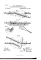
- Figure 1 is an under side plan view of a dividing trolley line frog or switch adapted for a left hand branch.
- Fig. 2 is a vertical longitudinal section cut on theline 2 2 in Fig. l.
- Fig. 3 is a transverse section thereof cut on the line 3 3 in Fig. l, and
- Fig. 4 is an under side plan view illustrating a modification as applied to a uniting switch joining a left hand branch.
- A indicate themain line wire of a trolley line,B a branch wire thereof, C a frog or switch at the j unction of the branch and main line,D the body thereof, E the entrance arm thereof, F the main line leaving arm thereof, G the branch line leaving arm thereof,H the binding ears thereof and I the trolley wheel.
- the entrance arm E is pivotallyconnected by a stud or pinJ to the flat under faceKof the body D, in such manner that it can be swung laterally to vary its position, and a nut or fastener L is provided near the outer portion of the arm for locking the latter in two or more positions relatively to the body D.
- a screw threaded pin M carried by the arm projects upwardly through one of two holes N N in the body D, and is engaged at the upper side of the body by one or more nuts L.
- the arm E can be removed from the one hole N and connected withV its ICO bolt M in the other hole N.
- These holes are disposed relatively to the arms F and G in such manner that when the arm E is connected through the one hole N it will be in line with the arm F, whereupon the frog or switch will be adapted for a left hand branch, and when the arm E is connected with the other hole N it will be in line with the arm G, whereupon the frog is adapted for a right hand branch.
- I provide a movable piece or tongue in the space between the opposite arms of a frog, switch or crossing, which tongueis preferably automatically shifted by the trolley wheel as it traverses the device.
- the body D is constructed with an elongated cut out portion O on its under face between its several arms, and a movable tongue P is pivotally connected at one end, and near to one of the arms, to the body, and free to swing at its other end into or out of line with one or both of the other arms.
- the tongue P being applied to a dividing frog or switch is pivotally connected at its front end on a pin Q traversing a hole R in the body D and engaged by nuts S for locking it in place, near to the entrance arm E of the frog, and the tongue extends thence outwardly toward the opposite arms F and G, between which it is free to swing.
- the body is constructed at the outer end of the tongue with an overhanging projection T above which enters a lip U on the tongue, whereby the outer end of the latter is sustained.
- the ends of the groove and the sides of the tongue constitute stops for limiting the movement of the latter.
- the tongue is constructed with a narrow onto the branch its trolley will be tilted in the same direction and will tilt the tongue into line with the branch tongue G.
- a uniting frog or switch is used.
- two tongues are employed, one pivoted adjecent to the branch entrance arm G', and the other adjacent to the line entrance arm F.
- the tongues in this instance are lettered P', and each swings toward and from the leaving arm lettered E of the frog here lettered C'.
- the leaving arm E is in this instance the adj ustable arm, and the body B' is constructed with overhanging projections T engaging 8o corresponding lips U on the dog.
- the adjacent pivotal ends of the tongue and the adjustable arm are rounded or beveled to permit movement or adjustment of these parts.
- the tongue? is of the same depth as the arms, whereby no change in level occurs as the trolley rides from one arm over the tongue to the next arm.
- the tongue is of conducting material and in conductive contact with the body D, so that there is a constant flow of current to the trolley while the tongue is traversed.
- the tongue In operation the tongue is moved by the movement of the trolley Wheel incident to the position of the trolley car as it passes the frog or switch. If the car proceeds along the main line, it will tilt the tongue into line with the main line arm F because of the tendency of the trolley to proceed forward in the direction taken by the car. If the'car is switched adapt it to the wires of the trolley line,in 001B.' f
Landscapes
- Engineering & Computer Science (AREA)
- Mechanical Engineering (AREA)
- Current-Collector Devices For Electrically Propelled Vehicles (AREA)
Description
(No Model.)l
H. M. GREENWOOD. OVERHEAD SWITCH PoR TROLLEY WIRES.
No. 525,598.V Patented Sept. 4, 1894.
I I j( '-\\\\\\\\\nne} u T .l/llllr FIG. "4'.
UNITED STATES PATENT OFFICE.
HUGH M. GREENWOOD, OF BROOKLYN, NEW YORK.
OVERHEAD SWITCH FOR TROLLEY-WIRES.
SPECIFICATION forming part of Letters Patent No. 525,598, dated September 4, 1894.
Application filed December 1, 1893. Serial No. 492,452. (No model.)
To all whom it may concern: j
Be it known that l, HUGH M. GREENWOOD, a cltizen of the United States, residing in Brooklyn, in'the county of Kings and State of New York, have invented certain new and useful Improvements in Overhead Switches, Frogs, and Crossings for Trolley-Lines, of which the following is a specification.
This invention relates to switches, frogs and crossings of the character used for trolley lines where the lines branch or cross.
Heretofore in such devices it has been customary to provide a body having arms corresponding to the several line wires, which arms have been cut away at their converging point 1n order to leave a space across which the trolley wheel should jump from the arms on which it approaches the frog to the arm on whlch it leaves the latter. The trolley in jumping this space is liable to miss the proper arm, and the jumping operation involves considerable sparking toward which a movable tongue bridging this space and moved by the trolley has been used.
Such frogs as have heretofore been constructed have consisted usually of one rigid casting, having a right hand arm for a right hand branch, a left hand arm for a left angle branch and uniformly diverging arms for a symmetrical branch.
My invention aims to provide an improved frog, switch or crossing which can be used either for a right or left angle branch, and in which sparking and the jumping of the trolley from one arm to another will be avoided, and the dangerof escape of the trolley greatly reduced by an improved tongue.
To this end in carrying out my invention l construct the frog, switch or crossing with one or more adjustable arms which can be tilted or adjusted to correspond with the direction of the line wire with which they coincide, whereby the device can be used either as a right or left hand frog, and I also provideia movable tongue of improved construction between the arms of the frog, switch or crossing, which tongue substantially completes the cut away portion between these arms, and is movable under the impulse of the trolley wheel in to line with either of the branch arms, or from either of the latter into line with the uniting arm. This tongue shifts with the shifting of the trolley wheel incident to the position of the trolley car, and thus is automatically thrown into position to complete the break between the two arms over which the trolley is to pass.. The tongue is of like shape to the arms, and of conducting material whereby throughout its passage over the tongue the trolley is in constant contact with the conducting material of the circuit.
In the accompanying drawings which illustrate certain adaptations of` my invention, Figure 1 is an under side plan view of a dividing trolley line frog or switch adapted for a left hand branch. Fig. 2 is a vertical longitudinal section cut on theline 2 2 in Fig. l. Fig. 3 is a transverse section thereof cut on the line 3 3 in Fig. l, and Fig. 4 is an under side plan view illustrating a modification as applied to a uniting switch joining a left hand branch.
Referring to the drawings let A indicate themain line wire of a trolley line,B a branch wire thereof, C a frog or switch at the j unction of the branch and main line,D the body thereof, E the entrance arm thereof, F the main line leaving arm thereof, G the branch line leaving arm thereof,H the binding ears thereof and I the trolley wheel.
According to one feature of my invention I construct the frog, switch or crossing in such manner that one or more of its arms can be adjusted or tilted to adapt the frog for use with either a right or left hand branch line.
VThis may be accomplished in various ways,
but I prefer the constrlction shown, wherein the entrance arm E is pivotallyconnected by a stud or pinJ to the flat under faceKof the body D, in such manner that it can be swung laterally to vary its position, and a nut or fastener L is provided near the outer portion of the arm for locking the latter in two or more positions relatively to the body D.
As shown a screw threaded pin M carried by the arm projects upwardly through one of two holes N N in the body D, and is engaged at the upper side of the body by one or more nuts L. By removing these nuts and unscrew# ing 4the stud J, the arm E can be removed from the one hole N and connected withV its ICO bolt M in the other hole N. These holes are disposed relatively to the arms F and G in such manner that when the arm E is connected through the one hole N it will be in line with the arm F, whereupon the frog or switch will be adapted for a left hand branch, and when the arm E is connected with the other hole N it will be in line with the arm G, whereupon the frog is adapted for a right hand branch.
According to another feature of my invention, I provide a movable piece or tongue in the space between the opposite arms of a frog, switch or crossing, which tongueis preferably automatically shifted by the trolley wheel as it traverses the device. I prefer to accomplish this in the manner shown in Figs. 1 to 3, wherein the body D is constructed with an elongated cut out portion O on its under face between its several arms, and a movable tongue P is pivotally connected at one end, and near to one of the arms, to the body, and free to swing at its other end into or out of line with one or both of the other arms. In Figs.1 to 3 the tongue P being applied to a dividing frog or switch is pivotally connected at its front end on a pin Q traversing a hole R in the body D and engaged by nuts S for locking it in place, near to the entrance arm E of the frog, and the tongue extends thence outwardly toward the opposite arms F and G, between which it is free to swing. The body is constructed at the outer end of the tongue with an overhanging projection T above which enters a lip U on the tongue, whereby the outer end of the latter is sustained. The ends of the groove and the sides of the tongue constitute stops for limiting the movement of the latter. These stops are arranged so that when a tongue is in one extreme position it will be in line between the entrance arm E and the corresponding line arm F, and when it is in the other eX- treme of position it will be in line with the entrance arm and the branch arm G.
The tongue is constructed with a narrow onto the branch its trolley will be tilted in the same direction and will tilt the tongue into line with the branch tongue G.
In the construction shown in Fig. 4 a uniting frog or switch is used. In this instance two tongues are employed, one pivoted adjecent to the branch entrance arm G', and the other adjacent to the line entrance arm F. The tongues in this instance are lettered P', and each swings toward and from the leaving arm lettered E of the frog here lettered C'. The leaving arm E is in this instance the adj ustable arm, and the body B' is constructed with overhanging projections T engaging 8o corresponding lips U on the dog.
As one tongue is engaged by its trolley it is swung into line with the arm E', and as it moves into position it will strike and displace the other tongue, since both are in the can horizontal plane. l
It will be seen that my invention provides. improvements in frogs, switches andcross ings for trolley wires which can be variously availed of, and that the invention is not lim- 9e ited to the exact features of construction, combination or arrangement set forth and shown, as these features may be modified, 0I' certain features of the invention employed separately from other features thereof, with'l g5 out departing from the essential features 0i the invention.
What I claim is, in overhead frogs,.8witehel, or crossings for trolley lines, the following-da f fined novel features or combinations, sub-weee stantially as hereinbefore set forth, namelr.. ,l l. In an overhead frog, switch or eroesillmw for trolley lines, a body, and wire arms, onesta@ said arms adjustably connected to said body..I
of said arms adjnstably connected to snidei wheel face a corresponding to the wheel faces y body, whereby its position can be shifted truc of the arms, and the length of this face is substantially equal to the distance between the opposite arms, whereby the tongue substantially fills the gap between these. The adjacent pivotal ends of the tongue and the adjustable arm are rounded or beveled to permit movement or adjustment of these parts. The tongue? is of the same depth as the arms, whereby no change in level occurs as the trolley rides from one arm over the tongue to the next arm. The tongue is of conducting material and in conductive contact with the body D, so that there is a constant flow of current to the trolley while the tongue is traversed.
In operation the tongue is moved by the movement of the trolley Wheel incident to the position of the trolley car as it passes the frog or switch. If the car proceeds along the main line, it will tilt the tongue into line with the main line arm F because of the tendency of the trolley to proceed forward in the direction taken by the car. If the'car is switched adapt it to the wires of the trolley line,in 001B.' f
bination with a movable tongue between scid arms for engaging the trolley and transfer ring it from one arm to another, said tongue and adjustable arm disposed to cooperate in; |15l f all positions of the latter. 3. In an overhead frog, switch or crossing.
for trolley lines, the body and arms, in com bination with a tongue between said arme pivoted at one end adjacent toone of said armeno and swinging at its other end into and out el. 1 line with another of said arms for tranlfoe-L ring the trolley between said arms, and intel*- engaging grooves and projections on seid: .i
body and tongue at the free end of the 1MM M5 for maintaining said tongue in position.
. 4. In an overhead frog, switch orcrossing j, f ,l
for trolley lines, the combination with die body D and the wire arms thereof, of ample` rate wire arm E removably connected toeduge i body, and interengaging locking devieel M' tween said arm and body, whereby the former r A l can be connected tothe latter in a plurality of different positions, substantially as and for the purpose set forth.
5. In an overhead frog, switch or crossing for trolley lines, the combination with the body D and the wire arms, of an arm E pivotally connected to said body at its inner end, whereby it can be s'wung to different positions to adapt it to the requirements of use.
6. In an overhead frog, switch or crossing for trolley 1ines,'the body D and wire arms, in combination with a movable tongue between said arms, carried on the under face of said body, and movable into and out of line with said arms for transferring the trolley from one to the other thereof, said tongue having a lip U at its free end, and said body having an overhanging projection T beneath said lip for supporting said tongue.
7. In a uniting overhead frog, switch or crossing for trolley lines, the body, two entering into line with said leaving arm for transferring the trolley from the former to the latter, and the other pivoted to said body adJacentl to the other of said entering arms and swinging into line with said leaving arm for transferring the trolley from the former to the latter, said tongues each moved by the action of the trolley in traversing it, each disposed in thesame plane, whereby when one tongue moves into position it displaces the other.
VIn witness whereof I have hereunto signed my name in the presence of two subscribin g witnesses.
HUGH M. GREENWOOD. Witnesses:
GEORGE H. FRASER, THOMAS F. WALLACE.
Publications (1)
| Publication Number | Publication Date |
|---|---|
| US525598A true US525598A (en) | 1894-09-04 |
Family
ID=2594390
Family Applications (1)
| Application Number | Title | Priority Date | Filing Date |
|---|---|---|---|
| US525598D Expired - Lifetime US525598A (en) | Overhead switch for trolley-wires |
Country Status (1)
| Country | Link |
|---|---|
| US (1) | US525598A (en) |
Cited By (1)
| Publication number | Priority date | Publication date | Assignee | Title |
|---|---|---|---|---|
| US2494409A (en) * | 1946-04-22 | 1950-01-10 | Cheatham Electric Switching Device Co | Trolley frog switch |
-
0
- US US525598D patent/US525598A/en not_active Expired - Lifetime
Cited By (1)
| Publication number | Priority date | Publication date | Assignee | Title |
|---|---|---|---|---|
| US2494409A (en) * | 1946-04-22 | 1950-01-10 | Cheatham Electric Switching Device Co | Trolley frog switch |
Similar Documents
| Publication | Publication Date | Title |
|---|---|---|
| US525598A (en) | Overhead switch for trolley-wires | |
| US764781A (en) | Switch for overhead-trolley tracks. | |
| US508672A (en) | Edward m | |
| US554517A (en) | Iialf to frederic cunningham | |
| US396313A (en) | Adjustable crossing and switch for overhead conductors | |
| US581023A (en) | foster | |
| US849994A (en) | Acute-angle crossing for electric railways. | |
| US563546A (en) | Trolley-wire frog | |
| US423495A (en) | Crossing for electric conductors | |
| US821424A (en) | Railway-switch. | |
| US848610A (en) | Overhead trolley-frog. | |
| US432581A (en) | Frog for overhead wires | |
| US541098A (en) | Crossing for trolley-wires | |
| US405627A (en) | Switch for suspended electric conductors | |
| US677463A (en) | Frog for use in connection with overhead conductors of electrical tramways or railways. | |
| US473362A (en) | short | |
| US431095A (en) | System of electrical locomotion | |
| US451696A (en) | John kuehnle | |
| US405965A (en) | Michael leary | |
| US632052A (en) | Switch for trolley-wires. | |
| US1140094A (en) | Plow for electric conduit-railways. | |
| US460571A (en) | Daniel w | |
| US590082A (en) | Trolley and conductor for electric railways | |
| US741785A (en) | Non-arcing clamp. | |
| US832312A (en) | Section-insulator for electric railways. |