US5249980A - Solderless connector - Google Patents
Solderless connector Download PDFInfo
- Publication number
- US5249980A US5249980A US07/746,178 US74617891A US5249980A US 5249980 A US5249980 A US 5249980A US 74617891 A US74617891 A US 74617891A US 5249980 A US5249980 A US 5249980A
- Authority
- US
- United States
- Prior art keywords
- insulation displacement
- engaging means
- engaging
- connector
- wire
- Prior art date
- Legal status (The legal status is an assumption and is not a legal conclusion. Google has not performed a legal analysis and makes no representation as to the accuracy of the status listed.)
- Expired - Lifetime
Links
- 238000006073 displacement reaction Methods 0.000 claims abstract description 85
- 238000009413 insulation Methods 0.000 claims abstract description 85
- 238000005452 bending Methods 0.000 claims 3
- 230000013011 mating Effects 0.000 description 3
- 239000002184 metal Substances 0.000 description 3
- 238000003780 insertion Methods 0.000 description 2
- 230000037431 insertion Effects 0.000 description 2
- 230000004048 modification Effects 0.000 description 2
- 238000012986 modification Methods 0.000 description 2
- 239000004020 conductor Substances 0.000 description 1
- 230000000694 effects Effects 0.000 description 1
Images


Classifications
-
- H—ELECTRICITY
- H01—ELECTRIC ELEMENTS
- H01R—ELECTRICALLY-CONDUCTIVE CONNECTIONS; STRUCTURAL ASSOCIATIONS OF A PLURALITY OF MUTUALLY-INSULATED ELECTRICAL CONNECTING ELEMENTS; COUPLING DEVICES; CURRENT COLLECTORS
- H01R4/00—Electrically-conductive connections between two or more conductive members in direct contact, i.e. touching one another; Means for effecting or maintaining such contact; Electrically-conductive connections having two or more spaced connecting locations for conductors and using contact members penetrating insulation
- H01R4/24—Connections using contact members penetrating or cutting insulation or cable strands
- H01R4/2416—Connections using contact members penetrating or cutting insulation or cable strands the contact members having insulation-cutting edges, e.g. of tuning fork type
- H01R4/2445—Connections using contact members penetrating or cutting insulation or cable strands the contact members having insulation-cutting edges, e.g. of tuning fork type the contact members having additional means acting on the insulation or the wire, e.g. additional insulation penetrating means, strain relief means or wire cutting knives
- H01R4/2462—Connections using contact members penetrating or cutting insulation or cable strands the contact members having insulation-cutting edges, e.g. of tuning fork type the contact members having additional means acting on the insulation or the wire, e.g. additional insulation penetrating means, strain relief means or wire cutting knives the contact members being in a slotted bent configuration, e.g. slotted bight
-
- H—ELECTRICITY
- H01—ELECTRIC ELEMENTS
- H01R—ELECTRICALLY-CONDUCTIVE CONNECTIONS; STRUCTURAL ASSOCIATIONS OF A PLURALITY OF MUTUALLY-INSULATED ELECTRICAL CONNECTING ELEMENTS; COUPLING DEVICES; CURRENT COLLECTORS
- H01R9/00—Structural associations of a plurality of mutually-insulated electrical connecting elements, e.g. terminal strips or terminal blocks; Terminals or binding posts mounted upon a base or in a case; Bases therefor
- H01R9/16—Fastening of connecting parts to base or case; Insulating connecting parts from base or case
-
- H—ELECTRICITY
- H01—ELECTRIC ELEMENTS
- H01R—ELECTRICALLY-CONDUCTIVE CONNECTIONS; STRUCTURAL ASSOCIATIONS OF A PLURALITY OF MUTUALLY-INSULATED ELECTRICAL CONNECTING ELEMENTS; COUPLING DEVICES; CURRENT COLLECTORS
- H01R13/00—Details of coupling devices of the kinds covered by groups H01R12/70 or H01R24/00 - H01R33/00
- H01R13/02—Contact members
- H01R13/10—Sockets for co-operation with pins or blades
- H01R13/11—Resilient sockets
- H01R13/113—Resilient sockets co-operating with pins or blades having a rectangular transverse section
-
- H—ELECTRICITY
- H01—ELECTRIC ELEMENTS
- H01R—ELECTRICALLY-CONDUCTIVE CONNECTIONS; STRUCTURAL ASSOCIATIONS OF A PLURALITY OF MUTUALLY-INSULATED ELECTRICAL CONNECTING ELEMENTS; COUPLING DEVICES; CURRENT COLLECTORS
- H01R4/00—Electrically-conductive connections between two or more conductive members in direct contact, i.e. touching one another; Means for effecting or maintaining such contact; Electrically-conductive connections having two or more spaced connecting locations for conductors and using contact members penetrating insulation
- H01R4/24—Connections using contact members penetrating or cutting insulation or cable strands
- H01R4/2495—Insulation penetration combined with permanent deformation of the contact member, e.g. crimping
Definitions
- This invention relates to a solderless connector.
- FIG. 5 is an exploded perspective view showing a conventional solderless connector 28 which has been disclosed, for instance, in Japanese Utility Model Unexamined Publication No. Sho. 60-138266, and which includes a connector housing 11, and insulation displacement terminals 12, to which electrical wires are connected.
- the connector housing 11 has terminal accommodating chambers 13, and a top wall 29 whose rear half has an opening 30 so that the terminal accommodating chambers 13 can be accessed.
- the insulation displacement terminals 12 are placed in respective ones of the terminal accommodating chambers 13, to which respective ones of the electrical wires 16 are connected by pressure, respectively.
- the insulation displacement terminal 12 is a female insulation displacement terminal which is formed as follows. First, a base plate 14 is formed by blanking a piece of electrically conductive metal plate, and then it is bent as follows: The front end portion of the base plate 14 is inserted into an elastic electrical contact part 15 which merges with a wire insulation displacement part 17.
- the wire insulation displacement part 17 is substantially inverted-U-shaped, and has a slot 17a into which the conductors 16b of the electrical wire are press-fitted with its cover 16a cut.
- the wire insulation displacement part 17 merges with the rear end portion of the insulation displacement terminal which is formed into a wire clamping part 18.
- a jig (not shown) is used to push the wire 16 into the wire insulation displacement part 17 from above.
- the conventional solderless terminal is disadvantageous for the following reasons Where the wire is large in diameter, as shown in FIG. 7, the inverted-U-shaped wire insulation displacement part 17 is spread when pushed, as a result of which the wire is not pushed sufficiently into the slot 17a. At the same time, the insulation displacement terminal 12 is increased in length, to extend from the terminal accommodating chamber 13, thus causing a short-circuit. The deformation of the wire insulation displacement part 17 may be prevented by increasing the thickness of the insulation displacement terminal 12. However, then it would be necessary to increase the force of insertion of the mating terminal (or male tab terminal (not shown)) correspondingly, impairing the operability of the connector.
- an object of this invention is to eliminate the above-described difficulties accompanying a conventional solderless connector.
- an object of the invention is to provide a solderless connector in which the insulation displacement terminal is prevented from being deformed when pushed, with the force of insertion of the mating terminal, i.e., the thickness of the insulation displacement terminal, maintained unchanged.
- a solderless connector having an insulation displacement terminal which is a plate member accommodated in a connector housing, the plate member including a wire insulation displacement part with a slot, in which, according to the invention, the plate member has first engaging portions formed therein so as to be located before and after the wire insulation displacement part.
- the connector housing has second engaging portions formed in the bottom thereof so as to be engageable with the first engaging portions, to prevent the longitudinal deformation of the wire insulation displacement part.
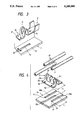
- FIG. 1 exploded perspective view showing one example of a solderless connector according to this invention
- FIG. 2 is a sectional view taken along line A--A in FIG. 1;
- FIGS. 3a, 3b and 3c are an exploded perspective view showing essential components of one modification of the solderless connector illustrated in FIG. 1;
- FIG. 4 is an exploded perspective view showing another example of the solderless connector according to the invention.
- FIG. 5 is an exploded perspective view showing a conventional solderless connector
- FIG. 6 is a perspective view showing essential components of the conventional solderless connector.
- FIG. 7 is a perspective view showing the insulation displacement terminal connected to a wire in the conventional solderless connector.
- a solderless connector according to this invention will be described with reference to FIG. 1, in which a female insulation displacement terminal 2 is accommodated in a connector housing 1.
- the female insulation displacement terminal 2 is formed as follows.
- a base plate 3 is formed by blanking a piece of electrically conductive metal plate, and is bent as follows: The front end portion is formed into an electrical contact part 4 which merges with a substantially inverted-U-shaped wire insulation displacement part 5 having a slot 5a.
- the rear end portion of the base plate 3 is formed into a wire clamping part 6.
- engaging protrusions 7a, 7b, and 7c are formed on the base plate 3, two before and one after the wire insulation displacement part 5, so as to protrude downwardly from the lower surface of the base plate 3.
- the engaging protrusions 7a and 7b are positioned before the wire insulation displacement part 5 so that a phantom line connecting the two protrusions 7a and 7b is perpendicular to the central axis of the base plate.
- the remaining protrusion 7c is positioned after the wire insulation displacement part 5, on the central axis.
- the front engaging protrusions 7a and 7b have their vertical end faces a and b facing forward, while the remaining rear engaging protrusion 7c has its vertical end face c facing backward.
- Three engaging grooves 9a, 9b, and 9c are formed in the bottom wall 8 of each of the terminal accommodating chambers of the connector housing 1 so that they are engageable with the above-described engaging protrusions 7a, 7b, and 7c, respectively.
- the engaging grooves 9a, 9b, and 9c have end walls a', b' and c' which abut the vertical end faces a, b, and c of the engaging protrusions 7a, 7b, and 7c, respectively.
- the distance L' between the end walls a, and b' and the end wall c' is equal to or slightly longer than the distance L between the end faces a and b of the front engaging protrusions 7a and 7b and the end face c of the rear engaging protrusion 7c.
- the insulation displacement terminal 2 is set in the terminal accommodating chamber with its engaging protrusions 7a, 7b, and 7c engaged with the engaging grooves 9a, 9b, and 9c of the connector housing 1, and the wire 10 is pushed into the slot 5a of the wire insulation displacement part 5 of the insulation displacement terminal 2 from above (in the direction of the arrow).
- the engaging protrusions 7a, 7b, and 7c formed before and after the wire insulation displacement part 5 are engaged with the engaging grooves 9a, 9b and 9c, and abut the end walls a', b', and c' of the respective engaging grooves 9a, 9b, and 9c.
- the part 5 will not spread longitudinally of the insulation displacement terminal 2.
- the insulation displacement terminal 2 is made of a thin metal plate in order to reduce the terminal inserting force, a large-diameter wire can be connected with ease.
- the rear engaging protrusion 7c can prevent the insulation displacement terminal from being moved backwardly; that is, it prevents the insulation displacement terminal from coming off the wire accommodating chamber when pulled backwardly.
- the engaging protrusions 7a through 7c are formed on the insulation displacement terminal 2, while the engaging grooves 9a through 9c for engaging with the engaging protrusions 7a through 7c are formed in the connector housing 1; however, the invention is not so limited. That is, the engaging protrusions may be formed on the connector housing, with the engaging grooves for engaging with the engaging protrusions formed in the insulation displacement terminal 2.
- the insulation displacement terminal 2 is a female insulation displacement terminal; however, it goes without saying that the technical concept of the invention may be applied to a solderless connector with male tab terminals with the same effects.
- solderless connector may be modified as shown in FIGS. 3a, 3b, and 3c. That is, engaging holes 19 and 19 are formed in the base plate 3, before the wire insulation displacement part 5', and an engaging protrusion 7c' is formed on the base plate 3, after the wire insulation displacement part 5, Engaging protrusions 20 and 20 for engaging with the engaging holes 19 and 19 and an engaging groove 9c' for engaging with the engaging protrusion 7c are formed. In contrast, the engaging protrusion and the engaging holes may be positioned respectively before and after the wire insulation displacement part 5'.
- the solderless connector comprises a branch connection type insulation displacement terminal 21.
- the insulation displacement terminal 21 is formed as follows: A rectangular base plate 22 is bent to have a substantially inverted-U-shaped wire pressure connecting part 23 having a plurality of cover cutting slots 23a.
- the base plate 22 has two engaging protrusions 7a and 7b, before the wire pressure connecting part 23 in such a manner that the phantom line connecting the two engaging protrusions 7a, and 7b, is perpendicular to the central axis of the base plate, and one engaging protrusion 7c" after the wire insulation displacement part 23 on the central axis of the base plate.
- These engaging protrusions 7a', 7b' and 7c" protrude from the lower surface of the base plate 22 so as to engage three engaging grooves 26a, 26b and 26c formed in the bottom of each of the terminal accommodating chambers in the connector housing 24, respectively.
- the distance between the end walls a" and b" of the engaging grooves 26a and 26b and the end wall c" of the engaging groove 26c is equal to the distance between the front protrusions 7a and 7b, and the rear protrusion 7c".
- the engaging protrusions 7a', 7b', and 7c" engage with the end walls a", b", and c" of the engaging grooves 26a, 26b, and 26c, respectively, to prevent the longitudinal spreading of the wire insulation displacement part 23.
- the inventive solderless connector when a wire is pushed into the slot of the insulation displacement terminal, the insulation displacement terminal is not deformed, although the insulation displacement terminal does not have increased wall thickness, even when a relatively great wire inserting force is applied.
- the wire can be connected to the solderless connector with high reliability, and can be connected with the mating connector with high efficiency.
- the insulation displacement terminal is prevented from coming off the connector housing even when pulled backwardly.
Landscapes
- Connections By Means Of Piercing Elements, Nuts, Or Screws (AREA)
Abstract
In a solderless connector having an insulation displacement terminal which is a plate member accommodated in a connector housing, the plate member includes a wire insulation displacement part with a slot, and has engaging protrusions before and after the wire insulation displacement part. The connector housing has engaging grooves formed in its bottom. The engaging protrusions are engaged with the engaging grooves, to prevent the longitudinal deformation of the wire insulation displacement part.
Description
This is a continuation of application Ser. No. 07/584,837 filed Sep. 19, 1990.
This invention relates to a solderless connector.
FIG. 5 is an exploded perspective view showing a conventional solderless connector 28 which has been disclosed, for instance, in Japanese Utility Model Unexamined Publication No. Sho. 60-138266, and which includes a connector housing 11, and insulation displacement terminals 12, to which electrical wires are connected. The connector housing 11 has terminal accommodating chambers 13, and a top wall 29 whose rear half has an opening 30 so that the terminal accommodating chambers 13 can be accessed. The insulation displacement terminals 12 are placed in respective ones of the terminal accommodating chambers 13, to which respective ones of the electrical wires 16 are connected by pressure, respectively.
The assembling of the solderless connector will become more apparent from FIG. 6, a perspective view showing essential components of the solderless connector. The insulation displacement terminal 12 is a female insulation displacement terminal which is formed as follows. First, a base plate 14 is formed by blanking a piece of electrically conductive metal plate, and then it is bent as follows: The front end portion of the base plate 14 is inserted into an elastic electrical contact part 15 which merges with a wire insulation displacement part 17. The wire insulation displacement part 17 is substantially inverted-U-shaped, and has a slot 17a into which the conductors 16b of the electrical wire are press-fitted with its cover 16a cut. The wire insulation displacement part 17 merges with the rear end portion of the insulation displacement terminal which is formed into a wire clamping part 18. A jig (not shown) is used to push the wire 16 into the wire insulation displacement part 17 from above.
The conventional solderless terminal is disadvantageous for the following reasons Where the wire is large in diameter, as shown in FIG. 7, the inverted-U-shaped wire insulation displacement part 17 is spread when pushed, as a result of which the wire is not pushed sufficiently into the slot 17a. At the same time, the insulation displacement terminal 12 is increased in length, to extend from the terminal accommodating chamber 13, thus causing a short-circuit. The deformation of the wire insulation displacement part 17 may be prevented by increasing the thickness of the insulation displacement terminal 12. However, then it would be necessary to increase the force of insertion of the mating terminal (or male tab terminal (not shown)) correspondingly, impairing the operability of the connector.
Accordingly, an object of this invention is to eliminate the above-described difficulties accompanying a conventional solderless connector.
More specifically, an object of the invention is to provide a solderless connector in which the insulation displacement terminal is prevented from being deformed when pushed, with the force of insertion of the mating terminal, i.e., the thickness of the insulation displacement terminal, maintained unchanged.
The foregoing and other objects of the invention have been achieved by the provision of a solderless connector having an insulation displacement terminal which is a plate member accommodated in a connector housing, the plate member including a wire insulation displacement part with a slot, in which, according to the invention, the plate member has first engaging portions formed therein so as to be located before and after the wire insulation displacement part. The connector housing has second engaging portions formed in the bottom thereof so as to be engageable with the first engaging portions, to prevent the longitudinal deformation of the wire insulation displacement part.
In the solderless connector, since engaging protrusions or holes provided before and after the wire insulation displacement part of the pressure connector are engaged with the second engaging portion formed in the bottom of the connector housing, the longitudinal movement of the insulation displacement terminal is limited, so that the insulation displacement terminal will never be deformed, even when a heavy wire is pushed into the slot of the wire insulation displacement part.
The nature, principle and utility of the invention will become more apparent from the following detailed description when read in conduction with the accompanying drawings.
In the accompanying drawings:
FIG. 1 exploded perspective view showing one example of a solderless connector according to this invention;
FIG. 2 is a sectional view taken along line A--A in FIG. 1;
FIGS. 3a, 3b and 3c are an exploded perspective view showing essential components of one modification of the solderless connector illustrated in FIG. 1;
FIG. 4 is an exploded perspective view showing another example of the solderless connector according to the invention;
FIG. 5 is an exploded perspective view showing a conventional solderless connector;
FIG. 6 is a perspective view showing essential components of the conventional solderless connector; and
FIG. 7 is a perspective view showing the insulation displacement terminal connected to a wire in the conventional solderless connector.
One example of a solderless connector according to this invention will be described with reference to FIG. 1, in which a female insulation displacement terminal 2 is accommodated in a connector housing 1. The female insulation displacement terminal 2 is formed as follows. As in the above-described conventional solderless connector, a base plate 3 is formed by blanking a piece of electrically conductive metal plate, and is bent as follows: The front end portion is formed into an electrical contact part 4 which merges with a substantially inverted-U-shaped wire insulation displacement part 5 having a slot 5a. The rear end portion of the base plate 3 is formed into a wire clamping part 6. In addition, engaging protrusions 7a, 7b, and 7c, substantially in the form of a triangular pyramid, are formed on the base plate 3, two before and one after the wire insulation displacement part 5, so as to protrude downwardly from the lower surface of the base plate 3.
More specifically, the engaging protrusions 7a and 7b are positioned before the wire insulation displacement part 5 so that a phantom line connecting the two protrusions 7a and 7b is perpendicular to the central axis of the base plate. The remaining protrusion 7c is positioned after the wire insulation displacement part 5, on the central axis. The front engaging protrusions 7a and 7b have their vertical end faces a and b facing forward, while the remaining rear engaging protrusion 7c has its vertical end face c facing backward.
Three engaging grooves 9a, 9b, and 9c are formed in the bottom wall 8 of each of the terminal accommodating chambers of the connector housing 1 so that they are engageable with the above-described engaging protrusions 7a, 7b, and 7c, respectively.
The engaging grooves 9a, 9b, and 9c have end walls a', b' and c' which abut the vertical end faces a, b, and c of the engaging protrusions 7a, 7b, and 7c, respectively. The distance L' between the end walls a, and b' and the end wall c' is equal to or slightly longer than the distance L between the end faces a and b of the front engaging protrusions 7a and 7b and the end face c of the rear engaging protrusion 7c.
As shown in FIG. 2, the insulation displacement terminal 2 is set in the terminal accommodating chamber with its engaging protrusions 7a, 7b, and 7c engaged with the engaging grooves 9a, 9b, and 9c of the connector housing 1, and the wire 10 is pushed into the slot 5a of the wire insulation displacement part 5 of the insulation displacement terminal 2 from above (in the direction of the arrow).
As was described above, the engaging protrusions 7a, 7b, and 7c formed before and after the wire insulation displacement part 5 are engaged with the engaging grooves 9a, 9b and 9c, and abut the end walls a', b', and c' of the respective engaging grooves 9a, 9b, and 9c. Hence, when the wire is pushed into the slot 5a of the wire insulation displacement part 5, the part 5 will not spread longitudinally of the insulation displacement terminal 2.
Hence, where the insulation displacement terminal 2 is made of a thin metal plate in order to reduce the terminal inserting force, a large-diameter wire can be connected with ease. In addition, the rear engaging protrusion 7c can prevent the insulation displacement terminal from being moved backwardly; that is, it prevents the insulation displacement terminal from coming off the wire accommodating chamber when pulled backwardly.
In the above-described solderless connector, the engaging protrusions 7a through 7c are formed on the insulation displacement terminal 2, while the engaging grooves 9a through 9c for engaging with the engaging protrusions 7a through 7c are formed in the connector housing 1; however, the invention is not so limited. That is, the engaging protrusions may be formed on the connector housing, with the engaging grooves for engaging with the engaging protrusions formed in the insulation displacement terminal 2. Furthermore, in the above-described solderless connector, the insulation displacement terminal 2 is a female insulation displacement terminal; however, it goes without saying that the technical concept of the invention may be applied to a solderless connector with male tab terminals with the same effects.
The above-described solderless connector may be modified as shown in FIGS. 3a, 3b, and 3c. That is, engaging holes 19 and 19 are formed in the base plate 3, before the wire insulation displacement part 5', and an engaging protrusion 7c' is formed on the base plate 3, after the wire insulation displacement part 5, Engaging protrusions 20 and 20 for engaging with the engaging holes 19 and 19 and an engaging groove 9c' for engaging with the engaging protrusion 7c are formed. In contrast, the engaging protrusion and the engaging holes may be positioned respectively before and after the wire insulation displacement part 5'.
Another example of the solderless connector according to the invention will be described with reference to FIG. 4. The solderless connector comprises a branch connection type insulation displacement terminal 21. The insulation displacement terminal 21 is formed as follows: A rectangular base plate 22 is bent to have a substantially inverted-U-shaped wire pressure connecting part 23 having a plurality of cover cutting slots 23a. The base plate 22 has two engaging protrusions 7a and 7b, before the wire pressure connecting part 23 in such a manner that the phantom line connecting the two engaging protrusions 7a, and 7b, is perpendicular to the central axis of the base plate, and one engaging protrusion 7c" after the wire insulation displacement part 23 on the central axis of the base plate. These engaging protrusions 7a', 7b' and 7c" protrude from the lower surface of the base plate 22 so as to engage three engaging grooves 26a, 26b and 26c formed in the bottom of each of the terminal accommodating chambers in the connector housing 24, respectively.
The distance between the end walls a" and b" of the engaging grooves 26a and 26b and the end wall c" of the engaging groove 26c is equal to the distance between the front protrusions 7a and 7b, and the rear protrusion 7c". In pushing the wire 27 into the slot 23a of the wire insulation displacement part 23 of the insulation displacement terminal 21, the engaging protrusions 7a', 7b', and 7c" engage with the end walls a", b", and c" of the engaging grooves 26a, 26b, and 26c, respectively, to prevent the longitudinal spreading of the wire insulation displacement part 23.
As is apparent from the above description, with the inventive solderless connector, when a wire is pushed into the slot of the insulation displacement terminal, the insulation displacement terminal is not deformed, although the insulation displacement terminal does not have increased wall thickness, even when a relatively great wire inserting force is applied. Thus, the wire can be connected to the solderless connector with high reliability, and can be connected with the mating connector with high efficiency. In addition, the insulation displacement terminal is prevented from coming off the connector housing even when pulled backwardly.
While the invention has been described in detail above with reference to preferred embodiments, various modifications within the scope and spirit of the invention will be apparent to people of working skill in this technological field. Thus, the invention should be considered as limited only by the scope of the appended claims.
Claims (15)
1. A solderless connector comprising a connector housing an an insulation displacement terminal which is formed by bending a base plate so that said insulation displacement terminal comprises an inverted U-shaped wire insulation displacement part having a slot, an electrical contact at the forward end of said base plate, and a wire clamping part at the rearward end of said base plate, said insulation displacement terminal adaptable to reside in said connector housing, wherein
said insulation displacement terminal comprises first engaging means formed on said base plate and located before and after said wire insulation displacement part, and
said connector housing comprises second engaging means formed in the bottom thereof and being in interlocking engagement with said first engaging means for preventing longitudinal deformation of said wire insulation displacement part relative to said connector housing due to a biasing force of said inverted U-shaped insulation displacement part exerted when a wire is being inserted into said insulation displacement part.
2. A solderless connector as claimed in claim 1, wherein said first engaging means comprise engaging protrusions.
3. A solderless connector as claimed in claim 1, wherein said first engaging means comprise engaging holes.
4. A solderless connector as claimed in claim 1, wherein said second engaging means comprise engaging protrusions.
5. A solderless connector as claimed in claim 1, wherein said second engaging means comprise engaging grooves.
6. A solderless connector as claimed in claim 1, wherein said second engaging means comprise engaging recesses.
7. A solderless connector as claimed in claim 1, wherein said second engaging means rigidly engage said first engaging means.
8. A solderless connector comprising a connector housing and a branch connection type insulation displacement terminal which is formed by bending a base plate so that said branch connection type insulation displacement terminal comprises a plurality of inverted U-shaped wire insulation displacement parts each having a slot, said branch connection type insulation displacement terminal residing in said connector housing, wherein
said branch connection type insulation displacement terminal comprises first engaging means formed on said base plate and located before and after said plurality of wire insulation displacement parts, and
said connector housing comprises second engaging means formed in the bottom thereof and being in interlocking engagement with said first engaging means, for preventing the longitudinal deformation of said wire insulation displacement part when a wire is inserted into each of said wire insulation displacement parts.
9. A solderless connector as claimed in claim 8, wherein said first engaging means comprise engaging protrusions.
10. A solderless connector as claimed in claim 8, wherein said first engaging means comprise engaging holes.
11. A solderless connector as claimed in claim 8, wherein said second engaging means comprise engaging protrusions.
12. A solderless connector as claimed in claim 8, wherein said second engaging means comprise engaging grooves.
13. A solderless connector as claimed in claim 8, wherein said second engaging means comprise engaging recesses.
14. A solderless connector as claimed in claim 8, wherein said second engaging means rigidly engage said first engaging means.
15. A solderless connector comprising a connector housing and an insulation displacement terminal which is formed by bending a base plate so that said insulation displacement terminal comprises an inverted U-shaped wire insulation displacement part having a slot, an electrical contact at the forward end of said base plate, an electrical contact at the forward end of said base plate, and a wire clamping part at the rearward end of said base plate, said insulation displacement terminal adaptable to reside in said connector housing, wherein
said insulation displacement terminal comprises first engaging means formed on said base plate and located before and after said wire insulation displacement part, and
said connector housing comprises second engaging means formed in the bottom thereof and being in interlocking engagement with said first engaging means for preventing longitudinal deformation of said wire insulation displacement part relative to said connector housing, wherein a biasing force of said inverted U-shaped insulation displacement part is utilized to retain said second engaging means in interlocking engagement with said first engaging means.
Priority Applications (1)
| Application Number | Priority Date | Filing Date | Title |
|---|---|---|---|
| US07/746,178 US5249980A (en) | 1989-10-30 | 1991-08-15 | Solderless connector |
Applications Claiming Priority (4)
| Application Number | Priority Date | Filing Date | Title |
|---|---|---|---|
| JP1-125608 | 1989-10-30 | ||
| JP1989125608U JPH0719091Y2 (en) | 1989-10-30 | 1989-10-30 | Insulation displacement connector |
| US58483790A | 1990-09-19 | 1990-09-19 | |
| US07/746,178 US5249980A (en) | 1989-10-30 | 1991-08-15 | Solderless connector |
Related Parent Applications (1)
| Application Number | Title | Priority Date | Filing Date |
|---|---|---|---|
| US58483790A Continuation | 1989-10-30 | 1990-09-19 |
Publications (1)
| Publication Number | Publication Date |
|---|---|
| US5249980A true US5249980A (en) | 1993-10-05 |
Family
ID=27315166
Family Applications (1)
| Application Number | Title | Priority Date | Filing Date |
|---|---|---|---|
| US07/746,178 Expired - Lifetime US5249980A (en) | 1989-10-30 | 1991-08-15 | Solderless connector |
Country Status (1)
| Country | Link |
|---|---|
| US (1) | US5249980A (en) |
Cited By (6)
| Publication number | Priority date | Publication date | Assignee | Title |
|---|---|---|---|---|
| US5567183A (en) * | 1992-12-24 | 1996-10-22 | Yazaki Corporation | Terminal retaining connector |
| US5616048A (en) * | 1995-06-26 | 1997-04-01 | The Whitaker Corporation | Electrical connector with electrical contact and strain relief |
| US5667414A (en) * | 1994-10-06 | 1997-09-16 | Stocko Metallwarenfabriken Henkels & Sohn Gmbh & Co. | Lockable flat plug sleeve for an electrical connector |
| US6099361A (en) * | 1997-05-09 | 2000-08-08 | Sumitomo Wiring Systems, Ltd. | Connector for a printed circuit board or an electric or electronic device |
| US6739897B1 (en) * | 2002-11-12 | 2004-05-25 | Comax Technology Inc. | Electrical connector with distribution contacts |
| CN106207614A (en) * | 2016-07-26 | 2016-12-07 | 厦门宏远达电器有限公司 | A kind of electric connecting structure of relay socket |
Citations (7)
| Publication number | Priority date | Publication date | Assignee | Title |
|---|---|---|---|---|
| US3510823A (en) * | 1968-04-29 | 1970-05-05 | Joseph J Cervenka | Fastener or terminal lug device and method of making same |
| US4010996A (en) * | 1976-01-14 | 1977-03-08 | Amp Incorporated | Intrinsic certification assembly technique for wiring components into an electrical apparatus |
| US4074929A (en) * | 1973-08-29 | 1978-02-21 | Amp Incorporated | Cable card edge connector |
| US4277124A (en) * | 1979-10-01 | 1981-07-07 | Amp Incorporated | Connector having wire-in-slot connecting means and crimped strain relief |
| US4296988A (en) * | 1980-02-20 | 1981-10-27 | Amp Incorporated | Connector with improved terminal support |
| US4377321A (en) * | 1980-11-17 | 1983-03-22 | Amp Incorporated | Carrier mounted terminals |
| US4527852A (en) * | 1983-08-09 | 1985-07-09 | Molex Incorporated | Multigauge insulation displacement connector and contacts therefor |
-
1991
- 1991-08-15 US US07/746,178 patent/US5249980A/en not_active Expired - Lifetime
Patent Citations (7)
| Publication number | Priority date | Publication date | Assignee | Title |
|---|---|---|---|---|
| US3510823A (en) * | 1968-04-29 | 1970-05-05 | Joseph J Cervenka | Fastener or terminal lug device and method of making same |
| US4074929A (en) * | 1973-08-29 | 1978-02-21 | Amp Incorporated | Cable card edge connector |
| US4010996A (en) * | 1976-01-14 | 1977-03-08 | Amp Incorporated | Intrinsic certification assembly technique for wiring components into an electrical apparatus |
| US4277124A (en) * | 1979-10-01 | 1981-07-07 | Amp Incorporated | Connector having wire-in-slot connecting means and crimped strain relief |
| US4296988A (en) * | 1980-02-20 | 1981-10-27 | Amp Incorporated | Connector with improved terminal support |
| US4377321A (en) * | 1980-11-17 | 1983-03-22 | Amp Incorporated | Carrier mounted terminals |
| US4527852A (en) * | 1983-08-09 | 1985-07-09 | Molex Incorporated | Multigauge insulation displacement connector and contacts therefor |
Cited By (6)
| Publication number | Priority date | Publication date | Assignee | Title |
|---|---|---|---|---|
| US5567183A (en) * | 1992-12-24 | 1996-10-22 | Yazaki Corporation | Terminal retaining connector |
| US5667414A (en) * | 1994-10-06 | 1997-09-16 | Stocko Metallwarenfabriken Henkels & Sohn Gmbh & Co. | Lockable flat plug sleeve for an electrical connector |
| US5616048A (en) * | 1995-06-26 | 1997-04-01 | The Whitaker Corporation | Electrical connector with electrical contact and strain relief |
| US6099361A (en) * | 1997-05-09 | 2000-08-08 | Sumitomo Wiring Systems, Ltd. | Connector for a printed circuit board or an electric or electronic device |
| US6739897B1 (en) * | 2002-11-12 | 2004-05-25 | Comax Technology Inc. | Electrical connector with distribution contacts |
| CN106207614A (en) * | 2016-07-26 | 2016-12-07 | 厦门宏远达电器有限公司 | A kind of electric connecting structure of relay socket |
Similar Documents
| Publication | Publication Date | Title |
|---|---|---|
| US5733155A (en) | Female contact | |
| US4416504A (en) | Contact with dual cantilevered arms with narrowed, complimentary tip portions | |
| US4838816A (en) | Electrical terminal having a receptacle contact section of low insertion force | |
| US4428636A (en) | Multi-contact connectors for closely spaced conductors | |
| US4699444A (en) | Electrical receptacle which assures positive connection | |
| US5435744A (en) | Sliding boot assembly for electrical connector | |
| US4963102A (en) | Electrical connector of the hermaphroditic type | |
| US6830472B1 (en) | Cable end connector assembly having locking member | |
| US6231396B1 (en) | Jack connector | |
| US5267881A (en) | Electrical connector | |
| US20010034163A1 (en) | Battery connector | |
| KR880001075A (en) | Electrical plug headers | |
| US20020048999A1 (en) | Electrical connector | |
| US6165008A (en) | Electrical connector for flexible flat cable | |
| US4577920A (en) | Electrical assembly with cable guiding member | |
| US6186837B1 (en) | Connector terminal | |
| US3412369A (en) | Contact with multiple termination | |
| US6159038A (en) | Compression header connector having strain relief and mountable to frame of hard disk drive | |
| US20040224563A1 (en) | Electrical connector having contact with pre-pressing structure | |
| US5249980A (en) | Solderless connector | |
| JP3097891B2 (en) | Shielded electrical connector | |
| GB2294817A (en) | Electrical terminal and connector assembly | |
| US6334790B2 (en) | Electrical connection and housing having a lance in a terminal accommodation chamber | |
| US4371227A (en) | Electric connector | |
| JP2916567B2 (en) | Joint connector |
Legal Events
| Date | Code | Title | Description |
|---|---|---|---|
| STCF | Information on status: patent grant |
Free format text: PATENTED CASE |
|
| FEPP | Fee payment procedure |
Free format text: PAYOR NUMBER ASSIGNED (ORIGINAL EVENT CODE: ASPN); ENTITY STATUS OF PATENT OWNER: LARGE ENTITY |
|
| REMI | Maintenance fee reminder mailed | ||
| FPAY | Fee payment |
Year of fee payment: 4 |
|
| SULP | Surcharge for late payment | ||
| FPAY | Fee payment |
Year of fee payment: 8 |
|
| FPAY | Fee payment |
Year of fee payment: 12 |