US5248962A - Display driver providing positive off-states - Google Patents
Display driver providing positive off-states Download PDFInfo
- Publication number
- US5248962A US5248962A US07/732,098 US73209891A US5248962A US 5248962 A US5248962 A US 5248962A US 73209891 A US73209891 A US 73209891A US 5248962 A US5248962 A US 5248962A
- Authority
- US
- United States
- Prior art keywords
- state
- segment
- bar graph
- decoder
- output signals
- Prior art date
- Legal status (The legal status is an assumption and is not a legal conclusion. Google has not performed a legal analysis and makes no representation as to the accuracy of the status listed.)
- Expired - Lifetime
Links
- PXXLQQDIFVPNMP-UHFFFAOYSA-N 3-(diethylcarbamoyl)benzoic acid Chemical compound CCN(CC)C(=O)C1=CC=CC(C(O)=O)=C1 PXXLQQDIFVPNMP-UHFFFAOYSA-N 0.000 description 6
- 238000010586 diagram Methods 0.000 description 2
- 238000003491 array Methods 0.000 description 1
- 230000007812 deficiency Effects 0.000 description 1
- 238000012986 modification Methods 0.000 description 1
- 230000004048 modification Effects 0.000 description 1
Images


Classifications
-
- G—PHYSICS
- G01—MEASURING; TESTING
- G01R—MEASURING ELECTRIC VARIABLES; MEASURING MAGNETIC VARIABLES
- G01R13/00—Arrangements for displaying electric variables or waveforms
- G01R13/40—Arrangements for displaying electric variables or waveforms using modulation of a light beam otherwise than by mechanical displacement, e.g. by Kerr effect
- G01R13/404—Arrangements for displaying electric variables or waveforms using modulation of a light beam otherwise than by mechanical displacement, e.g. by Kerr effect for discontinuous display, i.e. display of discrete values
Definitions
- the invention relates to a counting/decoding scheme for a multiplexed LED-array display driver usable for example, in the field of scanning-type displays.
- Prior art type display drivers such as those used with the Hewlett Packard HDSP-88XX Series of 101-element LED linear arrays (bar graphs) rely on standard TTL parts.
- the HDSP-88XX is a 101 element bar graph array.
- the linear array is arranged as ten groups of ten LED elements plus one additional element.
- the ten elements of each group have common cathodes.
- Like elements in the ten groups have common anodes.
- the device is addressed via 22 single-in-line pins extending from the back side of the display.
- a major problem with this type of device is that in some cases, undesirable "ghosts" or "phantom bars" can occur on the display.
- microprocessor driven While microprocessor programmability may be desirable in some situations, their faster clocks (e.g., in the MHz range) introduce or increase the likelihood of radio frequency interference (RFI) which ca necessitate heavy shielding. This is also obviously undesirable.
- RFID radio frequency interference
- the present invention ensures that only one LED segment of a bargraph display is on at a given time. According to one embodiment, this is done by controlling the timing sequence which controls the height of the bar.
- a counter which generates two clock signals, e.g., a source clock and a sink clock.
- the source clock runs ten times faster than the sink clock.
- a delay clock which may be a count to three delay clock.
- the circuitry of the present invention ensures that there is an OFF state associated with each ON state. This is in contradistinction to the prior art such as the Hewlett Packard type system, where one turns ON as the previous one is turning OFF.
- PAL logic is used.
- the specific logic used, preferably in one or more PALs, is one of the novel aspects of the present invention.
- the present invention avoids the use of a microprocessor which overcome the drawbacks of RFI discussed above and the need for shielding against such interference.
- FIG. 1 is a block diagram illustrating one embodiment of the present invention.
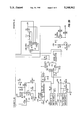
- FIG. 2 is a schematic circuit diagram corresponding to the element shown in FIG. 1.
- FIG. 3 is a chart representing a counting/decoding sequence according to one embodiment of the present invention.
- FIG. 1 there is shown a circuit which may be used to implement the preferred embodiment.
- a clock 10 which is connected to a counter 12.
- the counter 12 may be implemented by a PAL 20RA10, for example.
- the clock 10 may have multiple lines of outputs.
- the output of the counter 12 comprises a source clock, a delay clock and a sink clock. This combination and its function is believed to be a novel aspect of the present invention.
- an output of the counter 12 is provided to a decoder 14 which may also be implemented with PAL circuitry, for example, a PAL 20L10.
- the decoder 14 preferably comprises a BCD decoder and a one of three decoder and the counter 12 preferably comprises two BCD counters and a divide-by-three counter.
- the sink clock information is provided to a sink driver 16.
- the output of the decoder 14 is provided to source driver circuitry 18 which may include transistor source drivers.
- the output of the source driver circuitry and the sink driver 16 are provided to a multi-segment bargraph display 20, for example, the HDSP-88XX 101 element bargraph array.
- FIG. 2 A more detailed schematic of the circuit of FIG. 1 is shown in FIG. 2 with like components labeled with the reference numerals.
- the outputs 1QA-1QD of counter 12 comprise the source clock.
- Outputs QX and QY comprise the delay clock and outputs 2QA-2QD comprise the sink clock.
- the decoder 14 has a plurality of inputs including inputs A, B, C, D, X, Y and E. These inputs are further discussed in connection with the chart of FIG. 3 below.
- the output of the decoder comprises outputs 0-9 which are supplied to the transistor source drivers of the source driver circuitry 18.
- the output of the transistor source drivers are provided to the display 20 along with the outputs of the sink driver 16.
- FIG. 3 a chart representing a counting/decoding sequence for the multi-segment array multiplexed display driver according to the present invention.
- DCBA decoder input
- Delay represents the state of the X and Y inputs to decoder 14 which represent the state of the delay clock of counter 12.
- the delay clock is 01, 00 and 10 respectively.
- the decoder outputs ("/0"-"/9").
- a "1" may represent an OFF-state or no display and a "0" may represent an ON-state or a display, but this invention is not so limited.
- this represents the completely off state such that none of segments "/0" to "/9” are driven and no display is provided.
- the decoder outputs "0/"-"/9" are all 1's.
- the display is completely off.
- the second line (X, Y corresponding to 0,0) shows that the "/0" segment output is “0" which indicates that the segment is ON.
- the remaining segments (“/1"-"/9") however are “1” which indicates they are OFF.
- X,Y changes to 1,0 and once again, segment /0-/9 of the decoder outputs are all 1's which represent a completely OFF state.
- DCBA corresponding to 0001
- X,Y assumes the value 0,1 and the segments are completely OFF.
- the decoder outputs /0-/9 are all 1's.
- the letter E represents an enable bit and its operation will be readily apparent to one of ordinary skill in the art.
- the source clock corresponding to outputs 1QA-1QD of the counter 12 runs at a speed approximately ten times faster than the sink clock corresponding to outputs 2QA-2QD of the counter 12.
- the sink clock may be used to select one out of a group of ten displays and the source clock may be used to select the segment out of ten for the selected display.
- a count by three decoder is used.
- a count by four decoder may be used to achieve a 75 percent duty cycle.
Landscapes
- Physics & Mathematics (AREA)
- General Physics & Mathematics (AREA)
- Control Of Indicators Other Than Cathode Ray Tubes (AREA)
Abstract
Description
Claims (16)
Priority Applications (1)
| Application Number | Priority Date | Filing Date | Title |
|---|---|---|---|
| US07/732,098 US5248962A (en) | 1991-07-18 | 1991-07-18 | Display driver providing positive off-states |
Applications Claiming Priority (1)
| Application Number | Priority Date | Filing Date | Title |
|---|---|---|---|
| US07/732,098 US5248962A (en) | 1991-07-18 | 1991-07-18 | Display driver providing positive off-states |
Publications (1)
| Publication Number | Publication Date |
|---|---|
| US5248962A true US5248962A (en) | 1993-09-28 |
Family
ID=24942183
Family Applications (1)
| Application Number | Title | Priority Date | Filing Date |
|---|---|---|---|
| US07/732,098 Expired - Lifetime US5248962A (en) | 1991-07-18 | 1991-07-18 | Display driver providing positive off-states |
Country Status (1)
| Country | Link |
|---|---|
| US (1) | US5248962A (en) |
Citations (7)
| Publication number | Priority date | Publication date | Assignee | Title |
|---|---|---|---|---|
| US4150365A (en) * | 1975-07-02 | 1979-04-17 | Citizen Watch Co., Ltd. | Driver circuit for electrochromic display device |
| US4183021A (en) * | 1976-03-31 | 1980-01-08 | Licentia Patent-Verwaltungs-G.M.B.H. | Circuit arrangement |
| US4386347A (en) * | 1980-12-04 | 1983-05-31 | General Electric Company | Method of, and apparatus for, increased resolution slewing of a bar-graph-display data input/output system |
| US4398265A (en) * | 1980-09-15 | 1983-08-09 | Motorola, Inc. | Keyboard and display interface adapter architecture |
| US4511894A (en) * | 1981-12-17 | 1985-04-16 | Westinghouse Electric Corp. | Electronic display apparatus using time multiplexed data and control signals |
| US4743897A (en) * | 1985-10-09 | 1988-05-10 | Mitel Corp. | LED driver circuit |
| US5055840A (en) * | 1990-01-16 | 1991-10-08 | Carroll Touch Incorporated | Infrared touch input device and light emitted activation circuit |
-
1991
- 1991-07-18 US US07/732,098 patent/US5248962A/en not_active Expired - Lifetime
Patent Citations (7)
| Publication number | Priority date | Publication date | Assignee | Title |
|---|---|---|---|---|
| US4150365A (en) * | 1975-07-02 | 1979-04-17 | Citizen Watch Co., Ltd. | Driver circuit for electrochromic display device |
| US4183021A (en) * | 1976-03-31 | 1980-01-08 | Licentia Patent-Verwaltungs-G.M.B.H. | Circuit arrangement |
| US4398265A (en) * | 1980-09-15 | 1983-08-09 | Motorola, Inc. | Keyboard and display interface adapter architecture |
| US4386347A (en) * | 1980-12-04 | 1983-05-31 | General Electric Company | Method of, and apparatus for, increased resolution slewing of a bar-graph-display data input/output system |
| US4511894A (en) * | 1981-12-17 | 1985-04-16 | Westinghouse Electric Corp. | Electronic display apparatus using time multiplexed data and control signals |
| US4743897A (en) * | 1985-10-09 | 1988-05-10 | Mitel Corp. | LED driver circuit |
| US5055840A (en) * | 1990-01-16 | 1991-10-08 | Carroll Touch Incorporated | Infrared touch input device and light emitted activation circuit |
Non-Patent Citations (2)
| Title |
|---|
| Hewlett Packard Handbook, 101 Element Bar Graph Array , pp. 5 32 through 5 29, Jan. 1986. * |
| Hewlett-Packard Handbook, "101 Element Bar Graph Array", pp. 5-32 through 5-29, Jan. 1986. |
Similar Documents
| Publication | Publication Date | Title |
|---|---|---|
| US6239781B1 (en) | Gray-scale signal generating circuit and liquid crystal display | |
| US4499459A (en) | Drive circuit for display panel having display elements disposed in matrix form | |
| US7298357B2 (en) | Active matrix type flat-panel display device | |
| KR102006672B1 (en) | Display apparatus and method for generating enable signal for the same | |
| US5206635A (en) | Method and apparatus for multi-level tone display for liquid crystal apparatus | |
| GB1599733A (en) | Microcomputer for use with video display | |
| EP0387550A1 (en) | Display control device | |
| US5426446A (en) | Display device | |
| JPH1092323A5 (en) | ||
| US5248962A (en) | Display driver providing positive off-states | |
| GB1595861A (en) | Matrix drive system for liquid crystal display | |
| CN1728229B (en) | Display Driver Circuit with Grayscale Voltage Amplifier with Variable Driving Capability | |
| US4689618A (en) | Display apparatus time-division controlled in a dynamic driving system | |
| US3761766A (en) | Electronic indicia display system | |
| US5680148A (en) | Driving circuit for a display apparatus capable of display of an image with gray scales | |
| EP0476957B1 (en) | Method and apparatus for driving a display device | |
| JPS6256688B2 (en) | ||
| EP0267426B1 (en) | Dot matrix disply apparatus | |
| EP0484164B1 (en) | A row electrode driving circuit for a display apparatus | |
| EP0402848A2 (en) | Liquid crystal display apparatus and method of performing liquid crystal display | |
| US3603965A (en) | Information display circuit including means for blanking the display device | |
| EP0457440A2 (en) | Grey scale display | |
| US6222510B1 (en) | Display unit | |
| US5298920A (en) | Display device | |
| US20010048419A1 (en) | Method of gray scale generation for displays using a binary weighted clock |
Legal Events
| Date | Code | Title | Description |
|---|---|---|---|
| AS | Assignment |
Owner name: SONY CORPORATION OF AMERICA, NEW JERSEY Free format text: ASSIGNMENT OF ASSIGNORS INTEREST.;ASSIGNOR:RAPPOPORT, OREN P.;REEL/FRAME:005778/0531 Effective date: 19910715 |
|
| AS | Assignment |
Owner name: SONY ELECTRONICS INC., NEW JERSEY Free format text: CHANGE OF NAME;ASSIGNOR:SONY CORPORATION OF AMERICA;REEL/FRAME:006605/0977 Effective date: 19930601 |
|
| STCF | Information on status: patent grant |
Free format text: PATENTED CASE |
|
| FEPP | Fee payment procedure |
Free format text: PAYOR NUMBER ASSIGNED (ORIGINAL EVENT CODE: ASPN); ENTITY STATUS OF PATENT OWNER: LARGE ENTITY |
|
| FPAY | Fee payment |
Year of fee payment: 4 |
|
| FPAY | Fee payment |
Year of fee payment: 8 |
|
| FPAY | Fee payment |
Year of fee payment: 12 |