US5245179A - Cylindrical color filter driver for an optical reader - Google Patents
Cylindrical color filter driver for an optical reader Download PDFInfo
- Publication number
- US5245179A US5245179A US07/957,834 US95783492A US5245179A US 5245179 A US5245179 A US 5245179A US 95783492 A US95783492 A US 95783492A US 5245179 A US5245179 A US 5245179A
- Authority
- US
- United States
- Prior art keywords
- color filter
- faces
- cylinder
- filter driver
- motor
- Prior art date
- Legal status (The legal status is an assumption and is not a legal conclusion. Google has not performed a legal analysis and makes no representation as to the accuracy of the status listed.)
- Expired - Lifetime
Links
- 230000003287 optical effect Effects 0.000 title claims abstract description 7
- 238000000034 method Methods 0.000 abstract description 5
- 238000009434 installation Methods 0.000 description 4
- 238000004519 manufacturing process Methods 0.000 description 4
- 241000519995 Stachys sylvatica Species 0.000 description 3
- 230000005540 biological transmission Effects 0.000 description 3
- 239000003086 colorant Substances 0.000 description 2
- 238000010586 diagram Methods 0.000 description 2
- 238000012545 processing Methods 0.000 description 2
- 230000002441 reversible effect Effects 0.000 description 2
- 238000012546 transfer Methods 0.000 description 2
- 238000013461 design Methods 0.000 description 1
- 238000012986 modification Methods 0.000 description 1
- 230000004048 modification Effects 0.000 description 1
- 238000000926 separation method Methods 0.000 description 1
Images


Classifications
-
- G—PHYSICS
- G02—OPTICS
- G02B—OPTICAL ELEMENTS, SYSTEMS OR APPARATUS
- G02B26/00—Optical devices or arrangements for the control of light using movable or deformable optical elements
- G02B26/007—Optical devices or arrangements for the control of light using movable or deformable optical elements the movable or deformable optical element controlling the colour, i.e. a spectral characteristic, of the light
- G02B26/008—Optical devices or arrangements for the control of light using movable or deformable optical elements the movable or deformable optical element controlling the colour, i.e. a spectral characteristic, of the light in the form of devices for effecting sequential colour changes, e.g. colour wheels
-
- G—PHYSICS
- G01—MEASURING; TESTING
- G01J—MEASUREMENT OF INTENSITY, VELOCITY, SPECTRAL CONTENT, POLARISATION, PHASE OR PULSE CHARACTERISTICS OF INFRARED, VISIBLE OR ULTRAVIOLET LIGHT; COLORIMETRY; RADIATION PYROMETRY
- G01J3/00—Spectrometry; Spectrophotometry; Monochromators; Measuring colours
- G01J3/46—Measurement of colour; Colour measuring devices, e.g. colorimeters
- G01J3/50—Measurement of colour; Colour measuring devices, e.g. colorimeters using electric radiation detectors
-
- G—PHYSICS
- G02—OPTICS
- G02B—OPTICAL ELEMENTS, SYSTEMS OR APPARATUS
- G02B26/00—Optical devices or arrangements for the control of light using movable or deformable optical elements
- G02B26/08—Optical devices or arrangements for the control of light using movable or deformable optical elements for controlling the direction of light
- G02B26/10—Scanning systems
-
- H—ELECTRICITY
- H04—ELECTRIC COMMUNICATION TECHNIQUE
- H04N—PICTORIAL COMMUNICATION, e.g. TELEVISION
- H04N1/00—Scanning, transmission or reproduction of documents or the like, e.g. facsimile transmission; Details thereof
- H04N1/46—Colour picture communication systems
- H04N1/48—Picture signal generators
- H04N1/482—Picture signal generators using the same detector device sequentially for different colour components
-
- G—PHYSICS
- G01—MEASURING; TESTING
- G01J—MEASUREMENT OF INTENSITY, VELOCITY, SPECTRAL CONTENT, POLARISATION, PHASE OR PULSE CHARACTERISTICS OF INFRARED, VISIBLE OR ULTRAVIOLET LIGHT; COLORIMETRY; RADIATION PYROMETRY
- G01J3/00—Spectrometry; Spectrophotometry; Monochromators; Measuring colours
- G01J3/46—Measurement of colour; Colour measuring devices, e.g. colorimeters
- G01J3/50—Measurement of colour; Colour measuring devices, e.g. colorimeters using electric radiation detectors
- G01J3/51—Measurement of colour; Colour measuring devices, e.g. colorimeters using electric radiation detectors using colour filters
-
- G—PHYSICS
- G02—OPTICS
- G02B—OPTICAL ELEMENTS, SYSTEMS OR APPARATUS
- G02B7/00—Mountings, adjusting means, or light-tight connections, for optical elements
- G02B7/006—Filter holders
Definitions
- the present invention relates to a cylindrical color filter driver for an optical reader which utilizes a motor to rotate a cylindrical color filter assembly for permitting the color image of a document to be reproduced through a single color charge coupled device.
- FIG. 1 illustrates a rotary wheel type of color filter driver in which the color wheel which is referenced as 10 has red, blue and green color filters 1a,1b,1c and a transparent window 1d arranged around a circle, the top cover which is referenced as 2 has two LEDs (light emitting diodes) 3a, 3b respectively aligned with two photo detectors 4a,4b. Rotating the color wheel 10 causes light holes 6a,6b,6c to be respectively aligned with one LED 3b and one photo detector 4b at different times.
- Output signals of the photo detectors 4a,4b are transmitted to a signal processor so as to provide a respective start signal for each scanning and a respective start signal for red, green and blue scanning mode.
- This structure of color filter driver is expensive to manufacture, requires much installation space and provides low resolution performance. Because the red, blue and green color filters provide different light transmission rates, the charged couple device will be exposed to the different intensity of light during a continuous scanning of the primary colors, and therefore the signal data processing technique becomes complicated. Furthermore, executing a synchronizing control takes much time, and therefore the scanning speed can be not improved.
- FIG. 2 illustrates a sector disk type color filter driver. This structure of sector color filter driver still requires much installation space.
- FIG. 3 illustrates a linear color filter driver which utilizes a reversible motor to alternatively move a color filter assembly back and forth through a linear source. This structure of linear color filter driver is inexpensive to manufacture and requires much installation space. The reciprocating motion of the color filter assembly can not improve the scanning speed.
- the present invention eliminates the aforesaid disadvantages. It is therefore an object of the present invention to provide a cylindrical color filter driver which is compact and lightweight. It is another object of the present invention to provide a cylindrical color filter driver which provides a high resolution performance. It is still another object of the present invention to provide a cylindrical color filter driver which is inexpensive to manufacture.
- a cylindrical color filter driver includes a cylinder having red, blue and green color filters respectively covered on three spaced faces thereof alternatively separated by three spaced openings on the other three spaced faces thereof; a motor having an output shaft coupled to the cylinder at one end and controlled to rotate the cylinder on a mounting plate; and a position detector to detect reflective signals produced by reflective spots on the cylinder for controlling the revolving speed of the motor, the standard exposure point.
- FIG. 1 is an exploded view of a rotary wheel type color filter driver according to the prior art
- FIG. 2 is a front view of a sector disk type color filter driver according to the prior art
- FIG. 3 is a linear color filter driver according to the prior art
- FIG. 4a is an end view of a hexagonal cylinder according to the present invention, showing three color filters covered on three spaces sides thereof equiangularly separated by the other three open sides thereof;
- FIG. 4b is a perspective view of the hexagonal cylinder of FIG. 4a;
- FIG. 5 illustrates a cylindrical color filter driver embodying the present invention in which a step motor is used to drive a cylindrical color filter assembly
- FIG. 6 illustrates an alternate form of the present invention in which a DC motor is used to drive the cylindrical color filter assembly
- FIG. 7a illustrates the positioning and operation of the photoelectric position detector in the round disk rotated by the DC motor of FIG. 6;
- FIG. 7b illustrates the processing of the output signals of the photoelectric position detector
- FIG. 7c is a control circuit block diagram of the photoelectric position detector.
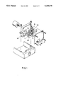
- FIG. 8 illustrates the cylindrical color filter driver of the present invention installed in an optical reader.
- the cylindrical color filter assembly 20 is made in the shape of a hexagonal prism having three spaced sides 7,8,9 respectively mounted with red, blue and green color filters and the other three spaced sides 7',8',9' opened. Therefore, the red, blue and green color filters are equiangularly spaced from one another by the open sides 7',8',9'.
- the cylindrical color filter driver 30 includes a step motor 11 to rotate the cylindrical color filter assembly 20.
- the cylindrical color filter assembly 20 has one end revolvably coupled to a mounting plate 13 and an opposite end coupled to the output shaft of the step motor 11. Therefore, the cylindrical color filter assembly 20 can be rotated by the step motor 11.
- the light of light source (not shown) passes through the color filter 7, 8 or 9 and comes into contact with a CCD (charge coupled device) 17.
- CCD charge coupled device
- a photoelectric position detector 14 detects a signal from a reflective spot 15 on the cylindrical color filter assembly 20 for controlling the revolving speed of the step motor 11.
- the cylindrical color filter assembly 20 is strong in structural, and therefore it can be rotated at a high revolving speed.
- a feedback type DC motor may be used to drive the cylindrical color filter assembly 20. As a feedback type DC motor is less expensive relative to a step motor, using a feedback type DC motor can reduce the cost of the cylindrical color filter driver.
- FIG. 6 illustrates an alternate form of the present invention in which a feedback DC motor 12 is used to replace the step motor 11 in FIG. 5.
- the DC motor 12 is controlled to rotate a round disk 21, which has a plurality of driving pins 18 spaced on the same side around the periphery thereof.
- the cylindrical color filter assembly 20 has one end coupled with a Geneva gear 19 disposed adjacent to the round disk 21. Rotating the round disk 21 causes the Geneva gear 19 to be rotated by the driving pins 18, and therefore the cylindrical color filter assembly 20 is rotated.
- the revolving speed of the DC motor 12 is automatically controlled by the photoelectric position detector 14, which detects the position change of the grating dot (colored, reflective spot) 15' and other white spots 22 on the round disk 21.
- the Geneva gear 19 is an index change gear, which ensures the color filters of the cylindrical color filter assembly to be maintained at accurate angular positions relative to the document being scanned, and lets the direct contact time between the color filters and the light be increased to the maximum, and therefore the revolving speed and the scanning speed can be greatly improved.
- FIGS. 7a, 7b and 7c illustrate the operation of the photoelectric position detector 14 in controlling the revolving speed of the cylindrical color filter assembly 20.
- the round disk 21 is marked with a grating dot 15' and a plurality of white spots 22 respectively arranged around a circle.
- the grating dot 15' is a reference spot.
- the white spots 22 are for improving the resolution of the feedback signal.
- output signals 23 from the photoelectric position detector 14 are treated through the process of signal separation 26 and turned into feedback signals 24 for controlling the revolving speed of the DC motor 12 and a signal 25 for detecting the absolute position (primary point, standard exposure time point, or start point for giving an instruction to operate the step motor).
- FIG. 7a illustrates the absolute position (primary point, standard exposure time point, or start point for giving an instruction to operate the step motor).
- FIG 7c illustrates the control block diagram of the cylindrical color filter driver in which Gmot(S) is the transfer function of the DC motor that is obtained according to the specifications of the DC motor; Gme(S) is obtained after the design of the color filter assembly; H(S) is the transfer function of the feedback circuit.
- the color filter red, blue or green
- red, blue or green may not be maintained perpendicular to the light passing through. This question is explained hereinafter:
- the thickness of the color filters commonly in use is about 0.10 m/m. This shift problem can be eliminated by making the hexagonal cylinder color filter assembly into a cylinder.
- the light transmission rate varies with the angular position of the color filter.
- the exposure of the CCD lasts a certain length of time.
- the color filter may be rotated from one angular position to another.
- the change in light transmission rate is about within 3.5% to 7.8%. This tolerance is acceptable and can be omitted.
- the numeral 27 designates a reflector
- the numeral 28 designates a fluorescent lamp tube
- the numeral 16 designates the route of the light rays
- the numeral 29 designates an optical focusing system (lens assembly)
- the numeral 30 designates a cylindrical color filter driver according to the present invention
- the numeral 17 designates a CCD (charge coupled device)
- the numeral 31 designates a CCD holder
- the numeral 32 designates a document to be read.
- the present invention is to provide a cylindrical color filter driver which utilizes a motor to rotate a cylindrical color filter assembly for the reproduction of colors, and which provides numerous advantages including accurate position and speed control, less installation space occupation, high scanning speed, high resolution, and low manufacturing cost.
Landscapes
- Physics & Mathematics (AREA)
- General Physics & Mathematics (AREA)
- Spectroscopy & Molecular Physics (AREA)
- Optics & Photonics (AREA)
- Engineering & Computer Science (AREA)
- Multimedia (AREA)
- Signal Processing (AREA)
- Astronomy & Astrophysics (AREA)
- Facsimile Scanning Arrangements (AREA)
- Mechanical Light Control Or Optical Switches (AREA)
Abstract
Description
Claims (3)
Priority Applications (2)
| Application Number | Priority Date | Filing Date | Title |
|---|---|---|---|
| US07/957,834 US5245179A (en) | 1992-10-08 | 1992-10-08 | Cylindrical color filter driver for an optical reader |
| DE4237236A DE4237236A1 (en) | 1992-10-08 | 1992-11-04 | Cylindrical color filter drive device for an optical reading device |
Applications Claiming Priority (1)
| Application Number | Priority Date | Filing Date | Title |
|---|---|---|---|
| US07/957,834 US5245179A (en) | 1992-10-08 | 1992-10-08 | Cylindrical color filter driver for an optical reader |
Publications (1)
| Publication Number | Publication Date |
|---|---|
| US5245179A true US5245179A (en) | 1993-09-14 |
Family
ID=25500211
Family Applications (1)
| Application Number | Title | Priority Date | Filing Date |
|---|---|---|---|
| US07/957,834 Expired - Lifetime US5245179A (en) | 1992-10-08 | 1992-10-08 | Cylindrical color filter driver for an optical reader |
Country Status (2)
| Country | Link |
|---|---|
| US (1) | US5245179A (en) |
| DE (1) | DE4237236A1 (en) |
Cited By (9)
| Publication number | Priority date | Publication date | Assignee | Title |
|---|---|---|---|---|
| US5986785A (en) * | 1996-03-14 | 1999-11-16 | Nec Corporation | Electronic apparatus with optical communication capability |
| EP1253456A1 (en) * | 2001-04-24 | 2002-10-30 | The Furukawa Electric Co., Ltd. | System and method for adjusting the angular orientation of an optical filter and optical module including this system |
| US20040007669A1 (en) * | 2002-07-09 | 2004-01-15 | Chun-Jen Chen | Image compensation structure and compensation method |
| US6710796B1 (en) * | 1999-10-07 | 2004-03-23 | Fuji Photo Film Co., Ltd. | Optical printer with color filter and optical printing method |
| US20090091759A1 (en) * | 2007-10-05 | 2009-04-09 | Lightwaves 2020, Inc. | Multiple Wavelength Optical Analyzer Device |
| WO2016123630A1 (en) | 2015-01-30 | 2016-08-04 | The United States Of America, As Represented By The Secretary, Department Of Health & Human Services | Devices and methods for detection of counterfeit or adulterated products and/or packaging |
| US10007920B2 (en) | 2012-12-07 | 2018-06-26 | The United States Of America, As Represented By The Secretary, Department Of Health And Human Services | Device and method for detection of counterfeit pharmaceuticals and/or drug packaging |
| US10101280B2 (en) | 2009-03-31 | 2018-10-16 | The United States Of America, As Represented By The Secretary, Department Of Health And Human Services | Device and method for detection of counterfeit pharmaceuticals and/or drug packaging |
| US11353475B2 (en) * | 2018-08-31 | 2022-06-07 | Appotronics Corporation Limited | Detecting device for detecting rotation speed of color wheel, light source system and projection device |
Families Citing this family (1)
| Publication number | Priority date | Publication date | Assignee | Title |
|---|---|---|---|---|
| DE29614692U1 (en) * | 1996-04-30 | 1996-10-24 | Balzers Prozess Systeme Vertriebs- und Service GmbH, 81245 München | Color wheel and imaging device with a color wheel |
Citations (4)
| Publication number | Priority date | Publication date | Assignee | Title |
|---|---|---|---|---|
| US2406318A (en) * | 1941-03-04 | 1946-08-27 | Westinghouse Electric Corp | Supervisory apparatus |
| US3492478A (en) * | 1966-05-18 | 1970-01-27 | American Cyanamid Co | Information retrieval from symbols based on presence and absence of coding components,the information being retrieved in discrete electrical pulses |
| US4804271A (en) * | 1985-07-04 | 1989-02-14 | Karl Cammann | Process for the improvement of selectivity of spectrometric measurements and an apparatus for the performance of the process |
| US5184253A (en) * | 1991-12-18 | 1993-02-02 | Steven Hwang | Fiber optic illuminator display |
Family Cites Families (5)
| Publication number | Priority date | Publication date | Assignee | Title |
|---|---|---|---|---|
| US2880267A (en) * | 1954-09-22 | 1959-03-31 | Columbia Broadcasting Syst Inc | Color television apparatus |
| JPS55111967A (en) * | 1979-02-21 | 1980-08-29 | Ricoh Co Ltd | Light radiation method to electrophotographic photoreceptor |
| JPH0675155B2 (en) * | 1986-09-05 | 1994-09-21 | シャープ株式会社 | Color image copying machine |
| JPH01147956A (en) * | 1987-12-03 | 1989-06-09 | Tokyo Electric Co Ltd | Color original reader |
| JPH02277374A (en) * | 1989-04-18 | 1990-11-13 | Seikosha Co Ltd | Image reader |
-
1992
- 1992-10-08 US US07/957,834 patent/US5245179A/en not_active Expired - Lifetime
- 1992-11-04 DE DE4237236A patent/DE4237236A1/en not_active Ceased
Patent Citations (4)
| Publication number | Priority date | Publication date | Assignee | Title |
|---|---|---|---|---|
| US2406318A (en) * | 1941-03-04 | 1946-08-27 | Westinghouse Electric Corp | Supervisory apparatus |
| US3492478A (en) * | 1966-05-18 | 1970-01-27 | American Cyanamid Co | Information retrieval from symbols based on presence and absence of coding components,the information being retrieved in discrete electrical pulses |
| US4804271A (en) * | 1985-07-04 | 1989-02-14 | Karl Cammann | Process for the improvement of selectivity of spectrometric measurements and an apparatus for the performance of the process |
| US5184253A (en) * | 1991-12-18 | 1993-02-02 | Steven Hwang | Fiber optic illuminator display |
Cited By (11)
| Publication number | Priority date | Publication date | Assignee | Title |
|---|---|---|---|---|
| US5986785A (en) * | 1996-03-14 | 1999-11-16 | Nec Corporation | Electronic apparatus with optical communication capability |
| US6710796B1 (en) * | 1999-10-07 | 2004-03-23 | Fuji Photo Film Co., Ltd. | Optical printer with color filter and optical printing method |
| EP1253456A1 (en) * | 2001-04-24 | 2002-10-30 | The Furukawa Electric Co., Ltd. | System and method for adjusting the angular orientation of an optical filter and optical module including this system |
| US20040007669A1 (en) * | 2002-07-09 | 2004-01-15 | Chun-Jen Chen | Image compensation structure and compensation method |
| US7446913B2 (en) * | 2002-07-09 | 2008-11-04 | Transpacific Ip, Ltd. | Image compensation structure and compensation method |
| US20090091759A1 (en) * | 2007-10-05 | 2009-04-09 | Lightwaves 2020, Inc. | Multiple Wavelength Optical Analyzer Device |
| US8049894B2 (en) * | 2007-10-05 | 2011-11-01 | Lightwaves 2020, Inc. | Multiple wavelength optical analyzer device |
| US10101280B2 (en) | 2009-03-31 | 2018-10-16 | The United States Of America, As Represented By The Secretary, Department Of Health And Human Services | Device and method for detection of counterfeit pharmaceuticals and/or drug packaging |
| US10007920B2 (en) | 2012-12-07 | 2018-06-26 | The United States Of America, As Represented By The Secretary, Department Of Health And Human Services | Device and method for detection of counterfeit pharmaceuticals and/or drug packaging |
| WO2016123630A1 (en) | 2015-01-30 | 2016-08-04 | The United States Of America, As Represented By The Secretary, Department Of Health & Human Services | Devices and methods for detection of counterfeit or adulterated products and/or packaging |
| US11353475B2 (en) * | 2018-08-31 | 2022-06-07 | Appotronics Corporation Limited | Detecting device for detecting rotation speed of color wheel, light source system and projection device |
Also Published As
| Publication number | Publication date |
|---|---|
| DE4237236A1 (en) | 1994-05-05 |
Similar Documents
| Publication | Publication Date | Title |
|---|---|---|
| US4797711A (en) | Image scanning apparatus | |
| JPH0224430B2 (en) | ||
| US5245179A (en) | Cylindrical color filter driver for an optical reader | |
| JPH0334712B2 (en) | ||
| US5953169A (en) | Rotary drum type optical filter apparatus | |
| US5033821A (en) | Element selecting device | |
| US5276556A (en) | Color separation system for a color scanner | |
| JPS648806B2 (en) | ||
| EP0317361A2 (en) | Filter change-over mechanism for use in color image reading apparatus | |
| JP3120433B2 (en) | Reader | |
| JPS61131960A (en) | Color picture reader | |
| JPH0468857A (en) | Switching device for optical member for color separation | |
| JP2754388B2 (en) | Color reader | |
| JPS6049314A (en) | Optical path division and color separation device for color image reading optical system | |
| JPS62291259A (en) | Reader | |
| JPH10319297A (en) | Image pickup lens with illumination optical system, and image pickup device | |
| SU1148017A1 (en) | Device for recording color pictures on black-and-white photographic material | |
| JPH0662179A (en) | Image input device | |
| JPH10112778A (en) | Color image reader | |
| JPH0240608A (en) | Filter converting device | |
| JPH05328035A (en) | Lamp unit for reflection and transmission reading and lamp unit for reflection reading | |
| JPH06266877A (en) | Optical reader | |
| JPH03126363A (en) | Image reading device | |
| JPS6014565A (en) | Color original reader | |
| JPS5957562A (en) | Original reading device |
Legal Events
| Date | Code | Title | Description |
|---|---|---|---|
| AS | Assignment |
Owner name: UMAX DATA SYSTEM INC., TAIWAN Free format text: ASSIGNMENT OF ASSIGNORS INTEREST.;ASSIGNOR:CHANG, SHIH-CHUNG;REEL/FRAME:006385/0996 Effective date: 19920920 |
|
| STCF | Information on status: patent grant |
Free format text: PATENTED CASE |
|
| FEPP | Fee payment procedure |
Free format text: PAYOR NUMBER ASSIGNED (ORIGINAL EVENT CODE: ASPN); ENTITY STATUS OF PATENT OWNER: LARGE ENTITY |
|
| FPAY | Fee payment |
Year of fee payment: 4 |
|
| FPAY | Fee payment |
Year of fee payment: 8 |
|
| FPAY | Fee payment |
Year of fee payment: 12 |
|
| AS | Assignment |
Owner name: VEUTRON CORPORATION, TAIWAN Free format text: CHANGE OF NAME;ASSIGNOR:UMAX DATA SYSTEMS INC.;REEL/FRAME:016800/0203 Effective date: 20021029 |
|
| AS | Assignment |
Owner name: TRANSPACIFIC IP, LTD.,TAIWAN Free format text: ASSIGNMENT OF ASSIGNORS INTEREST;ASSIGNOR:VEUTRON CORPORATION;REEL/FRAME:017564/0747 Effective date: 20050706 Owner name: TRANSPACIFIC IP, LTD., TAIWAN Free format text: ASSIGNMENT OF ASSIGNORS INTEREST;ASSIGNOR:VEUTRON CORPORATION;REEL/FRAME:017564/0747 Effective date: 20050706 |
|
| FEPP | Fee payment procedure |
Free format text: PAYER NUMBER DE-ASSIGNED (ORIGINAL EVENT CODE: RMPN); ENTITY STATUS OF PATENT OWNER: LARGE ENTITY Free format text: PAT HOLDER NO LONGER CLAIMS SMALL ENTITY STATUS, ENTITY STATUS SET TO UNDISCOUNTED (ORIGINAL EVENT CODE: STOL); ENTITY STATUS OF PATENT OWNER: LARGE ENTITY Free format text: PAYOR NUMBER ASSIGNED (ORIGINAL EVENT CODE: ASPN); ENTITY STATUS OF PATENT OWNER: LARGE ENTITY |
|
| AS | Assignment |
Owner name: TRANSPACIFIC SYSTEMS, LLC, DELAWARE Free format text: ASSIGNMENT OF ASSIGNORS INTEREST;ASSIGNOR:TRANSPACIFIC IP LTD.;REEL/FRAME:023107/0267 Effective date: 20090618 Owner name: TRANSPACIFIC SYSTEMS, LLC,DELAWARE Free format text: ASSIGNMENT OF ASSIGNORS INTEREST;ASSIGNOR:TRANSPACIFIC IP LTD.;REEL/FRAME:023107/0267 Effective date: 20090618 |