US5234076A - Tree stand - Google Patents
Tree stand Download PDFInfo
- Publication number
- US5234076A US5234076A US07/794,781 US79478191A US5234076A US 5234076 A US5234076 A US 5234076A US 79478191 A US79478191 A US 79478191A US 5234076 A US5234076 A US 5234076A
- Authority
- US
- United States
- Prior art keywords
- tree
- tree stand
- members
- stand
- main frame
- Prior art date
- Legal status (The legal status is an assumption and is not a legal conclusion. Google has not performed a legal analysis and makes no representation as to the accuracy of the status listed.)
- Expired - Lifetime
Links
- 239000002184 metal Substances 0.000 claims abstract description 8
- 229910000831 Steel Inorganic materials 0.000 abstract description 4
- 239000004744 fabric Substances 0.000 abstract description 4
- 230000000149 penetrating effect Effects 0.000 abstract description 4
- 239000010959 steel Substances 0.000 abstract description 4
- 230000009194 climbing Effects 0.000 abstract description 2
- 238000010276 construction Methods 0.000 abstract description 2
- 238000003466 welding Methods 0.000 description 3
- 230000001154 acute effect Effects 0.000 description 2
- 230000000737 periodic effect Effects 0.000 description 2
- 241001503987 Clematis vitalba Species 0.000 description 1
- 241000238631 Hexapoda Species 0.000 description 1
- 206010061217 Infestation Diseases 0.000 description 1
- 230000002493 climbing effect Effects 0.000 description 1
- 201000010099 disease Diseases 0.000 description 1
- 208000037265 diseases, disorders, signs and symptoms Diseases 0.000 description 1
- 239000006260 foam Substances 0.000 description 1
- 238000009434 installation Methods 0.000 description 1
- 210000003127 knee Anatomy 0.000 description 1
- 230000035515 penetration Effects 0.000 description 1
- 230000002093 peripheral effect Effects 0.000 description 1
- 238000009877 rendering Methods 0.000 description 1
- 239000011435 rock Substances 0.000 description 1
- 125000000391 vinyl group Chemical group [H]C([*])=C([H])[H] 0.000 description 1
- 229920002554 vinyl polymer Polymers 0.000 description 1
- XLYOFNOQVPJJNP-UHFFFAOYSA-N water Substances O XLYOFNOQVPJJNP-UHFFFAOYSA-N 0.000 description 1
Images


Classifications
-
- A—HUMAN NECESSITIES
- A01—AGRICULTURE; FORESTRY; ANIMAL HUSBANDRY; HUNTING; TRAPPING; FISHING
- A01M—CATCHING, TRAPPING OR SCARING OF ANIMALS; APPARATUS FOR THE DESTRUCTION OF NOXIOUS ANIMALS OR NOXIOUS PLANTS
- A01M31/00—Hunting appliances
- A01M31/02—Shooting stands
Definitions
- This invention relates to the field of hunting tree stands.
- Such stands have been developed and are known for providing a positioning for still hunters in forests. They derive from fixed tree mounted hunting platforms, and were devised to provide a portable apparatus for temporary installation in trees for supporting hunters.
- Such stands in order to be safe, involve combinations of various penetrating attachments to fix the stand to the tree for support it has been found that such penetration, especially of the living inner bark, injures the tree, rendering it more susceptible to insect infestation or disease. This problem is considered sufficiently acute that many forest mangers, especially in the lumber and paper industries now ban the use of tree stands.
- Tree stands of the current art use various forms of attachment to the tree; such are shown in U.S. Pat. Nos. 4,452,338; 4,417,645; 4316526; 4796364; 4247030; 4331216; 4742888; 4669194 and in the commercially sold unit under the trademark "Porta-climb". All these attachments are relatively rigid, and as the climber ascends, the stand tends to rock or sway under the user's movement.
- a tree stand for hunters is constructed of two platforms. Both platforms have a supporting metal frame, one covered with open metal grid for standing, and the other having a web fabric seat for comfortable seating. Each platform is supported by rigid, folding side rails, which fold for easy storage.
- a flexible, encased steel cable extends from one side rail around the trunk of the tree, and is fastened to the other side rail, and adjusted in length by a snap ring clip.
- a blunt, round edged toothed blade extends from the metal frame, and, in combination with the encased cable, holds the stand securely to the tree under load, but without penetrating the bark or otherwise injuring the tree.
- the encased cable and folding supports conform to the shape of the tree, and give the user a secure feeling both while climbing and while sitting or standing in the elevated stand.
- a further object of my invention is to provide an increased feeling of stability, comfort and safety to the user of a tree stand.
- a further object of my invention is to provide a tree stand having an improved, attachment to a tree, which is more stable, yet is easily adapted to various size trees.
- a further object of my invention is to show a tree stand which may be quickly set up for any size tree and as quickly taken down and prepared for storage or travel.
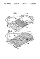
- FIG. 1 is a view of the upper, seating platform of my invention.
- FIG. 2 is a view of the lower, standing platform of my invention.
- FIG. 3 is a detail view of the cable attachment to the folding sides of the invention.
- FIG. 4 is a view of the attachment of the stand to a tree, showing a cut away tree bark section.
- FIG. 5 is an end view of a platform of the invention showing the folding sides for storage or travel.
- FIG. 6 is a view of the blades of the stand.
- the inventive tree stand 2 comes as two units, each embodying the inventive features below claimed. These two units are referred to herein as the seating platform 2A and the standing platform 2B respectively, and this terminology will be apparent to those skilled in the use of such platforms.
- Two such platforms are provided so as to permit climbing action up the trunk 4 of a tree, by successive movement of first one and then the other platform, while the user is supported by the tree stand. This use will be further shown below.
- FIG. 1 shows the seating platform 2A, which in use is always the upper platform of the two.
- Seating platform 2A is comprised of an outer peripheral frame 6 which defines the shape of each platform 2 and is the main structural member of each platform 2.
- This frame 6 is made preferably of 3/4 or 1 inch electrical conduit, which combine the requisite qualities of rigidity, lightness and strength. Any suitable tubing may, of course, be substituted.
- the frame 6 is in the form of an open U.
- An cross support 8 braces the open end of the U; this cross support 8 is also of conduit or tubing, preferably fastened to frame 6 by welding.
- Cross support 8 may also optionally be covered with a soft, water resistant padding such as vinyl covered foam. This cross support 8 is spaced a distance from the open end of the frame 6.
- the base 12 of the U shape of the frame 6 may optionally also be covered with a padding 14; this serves to protect the user's knees when moving from an outward facing sitting position.
- a flexible net or fabric seat 16 extends from one side 18a of the frame 6 to the other side 18b; this net seat 16 preferably is free to slide along the frame sides 18a,b, permitting it to be positioned as desired by the user.
- Two arcuate tree base support tubes 20 extend from a point 22 at the center of to cross support 8 to points near the open ends 24a,b of the frame 6. As these arcuate tree base support tubes 20 bear the weight of tree stand 2 and user, they are of a heavier construction than the frame 6, typically being 1 inch diameter conduit or 1/2 inch diameter tubing or conduit, but otherwise are hollow steel tubes, fastened preferably by welding.
- each tree base support tube 20 extending for a distance near the middle of each base support tube, are welded support blades 26.
- Each blade 26 generally is tangent to the curvature of the base support tube 20, and is formed of a thick, rectangular plate having a blunt, rounded outer edge 28, which is interrupted to form broad blunt segments or teeth 30.
- the support blades 26 are four inches wide and about 1/8 inch thick; the individual segments 30 are about 1 inch wide each, there being four such segments 30, separated by small spaces 32.
- each blade 26 is tangent to the tree trunk for best support.
- a first side support 36a is a length of conduit, of the same size as the frame 6, terminating at one end 37 in a T-shaped cross tubing section 38a; the other end 39 is to the end 24a of the frame by a pivotal attaching means the side support 36 is perpendicular to the side 18 of the frame 6, but can fold from an upright position to a position flat against the frame 6.
- the second side support 36b is similar except that the T-shaped cross tubing section 38b is extended for a distance along the length of the side 18b of the frame 6 to a point adjacent the frame 6, forming a triangular cross section with respect to the side 18b of the frame.
- This elongate T-shaped cross tubing section 38b is provided with periodic through holes 40.
- a support cable 42 preferably comprised of a steel cable covered with a rubber outer tubing, is affixed at a first end to the frame at a point 44 near the base of the U-shape.
- This cable 42 extends from this point of fixation 44 through the first side support T-shaped cross tube 38a; it terminates in a second, free end 48 which is a closed loop adapted to receive a fastening pin 50.
- a second, short cable stub 52 is affixed at a first end to the frame at a point 54 near the base of the U-shape, but on the opposite side 18b from the support cable 42; this stub cable 52 is affixed at its other end 56 into the second side support 36b.
- the free end 48 of the cable 42 may be inserted into the second side support T-shaped cross tube 38b, forming a tree trunk enclosing loop; the size of this loop is adjusted by fastening the free end 48 within the cross tube 38b by a PTO ring 50 inserted through one of the periodic holes 40 provided in the cross tube 38b.
- the second platform 2B is constructed in the same manner as the first except that, instead of a seat 16, a rigid supporting floor base 60 is provided of expanded metal, for example of 13 gauge, fastened to the frame 6 by welding. Additional cross supports 62 may be provided to stiffen the floor base 60 to support the weight of a standing user.
- This foot strap 64 may be cloth belting, fastened to the frame 6 at each side 18 and to the floor base 60 in the center of the foot strap 64, forming two loops adapted to receive the toe of a user's boots.
- the side support 36a,b of both platforms 2 are unfolded.
- the second, standing platform 2B is then attached around a chosen tree by running the cable free end 48 around the trunk 4 and fastening in within the cross tube 38b with a PTO ring 50 so that the tree trunk 4 is closely but not tightly encircled.
- the platform 2 When the platform 2 is so adjusted, it may be raised a distance up the trunk 4.
- the weight of the platform 2 is sufficient so that the combination of the support cable 42 and the blunt blades 26 grip the tree, supporting the platform 2.
- the blades 26 grip the bark 66 of the tree but do not penetrate the inner bark 68, and thus no damage occurs to the tree. Any slippage due to the lack of penetrating spikes is prevented by the conformable, opposing grip of the support cable 42, which conforms to the shape of the trunk.
- the standing platform 2B is fastened around the tree, the user then stands on this platform and fastens, in the same manner, the seating platform 2A to the tree. Since this platform 2A should be at waist level, the user's body must be inserted within the frame 6.
- the seat 16 is slidable along the frame sides 18, so that it can be easily moved out of the way.
- seat 16 may be formed of a padded folding seat, fastened between sides 18.
- the user may easily adjust platform height by sitting in the seat 16, and, placing his feet in the foot strap 64, may easily raise the standing platform 2B, or by standing on the standing platform 2B, raise the seating platform 2A.
- the seat 16 provides a comfortable, adjustable seat for a relaxed posture, yet the hunter may readily come to a standing position, free of the seat 61 which moves out of the way.
- the invention provides a more effective attachment of a hunting platform to a tree, without the damage to the tree of the prior art tree stands, and with a significant increase in versatility of use.
Landscapes
- Life Sciences & Earth Sciences (AREA)
- Engineering & Computer Science (AREA)
- Insects & Arthropods (AREA)
- Pest Control & Pesticides (AREA)
- Wood Science & Technology (AREA)
- Zoology (AREA)
- Environmental Sciences (AREA)
- Special Chairs (AREA)
Abstract
Description
Claims (16)
Priority Applications (1)
| Application Number | Priority Date | Filing Date | Title |
|---|---|---|---|
| US07/794,781 US5234076A (en) | 1990-09-14 | 1991-11-18 | Tree stand |
Applications Claiming Priority (2)
| Application Number | Priority Date | Filing Date | Title |
|---|---|---|---|
| US58303590A | 1990-09-14 | 1990-09-14 | |
| US07/794,781 US5234076A (en) | 1990-09-14 | 1991-11-18 | Tree stand |
Related Parent Applications (1)
| Application Number | Title | Priority Date | Filing Date |
|---|---|---|---|
| US58303590A Continuation | 1990-09-14 | 1990-09-14 |
Publications (1)
| Publication Number | Publication Date |
|---|---|
| US5234076A true US5234076A (en) | 1993-08-10 |
Family
ID=27078715
Family Applications (1)
| Application Number | Title | Priority Date | Filing Date |
|---|---|---|---|
| US07/794,781 Expired - Lifetime US5234076A (en) | 1990-09-14 | 1991-11-18 | Tree stand |
Country Status (1)
| Country | Link |
|---|---|
| US (1) | US5234076A (en) |
Cited By (29)
| Publication number | Priority date | Publication date | Assignee | Title |
|---|---|---|---|---|
| US5507362A (en) * | 1995-02-15 | 1996-04-16 | Krueger; Wayne C. | Tree stand torso bar |
| USD373427S (en) | 1995-05-08 | 1996-09-03 | Russom Terry L | Tree stand |
| US5588499A (en) * | 1992-09-10 | 1996-12-31 | Carriere; Steven N. | Tree stand |
| US5680910A (en) * | 1995-01-03 | 1997-10-28 | Sarphie, Iv; Joe E. | Climbing tree stand |
| US5862883A (en) * | 1995-03-10 | 1999-01-26 | Jennifer Carriere | Tree stand |
| US5921348A (en) * | 1994-04-19 | 1999-07-13 | L & L Enterprises, Inc. | Convertible treestand for rifle/bow use |
| US5979603A (en) * | 1995-01-06 | 1999-11-09 | Summit Specialties, Inc. | Portable tree stand having fiber composite platform |
| US6082492A (en) * | 1997-05-01 | 2000-07-04 | Yerger; Joseph W. | Safety belt for climbing tree stand |
| US6199660B1 (en) | 1999-06-21 | 2001-03-13 | Paul H. Meeks | Ladder stand stabilizing device |
| US6308801B1 (en) | 1999-02-04 | 2001-10-30 | John D. Futch | Tree climbing apparatus |
| US6523642B1 (en) | 2001-09-05 | 2003-02-25 | Buckshot, Inc. | Adjustable tree stand |
| US6568505B1 (en) | 2000-02-04 | 2003-05-27 | D'acquisto Andrae T. | Cam operated holding belt for tree stand |
| US6578913B2 (en) * | 2001-07-27 | 2003-06-17 | Richard W. Wilhelm | Seat and climbing aid for tree stand |
| US6588546B1 (en) | 2002-04-04 | 2003-07-08 | Lewis Forrest | Tree stand |
| US6652027B1 (en) * | 2002-08-07 | 2003-11-25 | Dennis Pardonnet | Padded backrest device with stand-off spacer elements particularly for use with a tree trunk base |
| US6662903B2 (en) | 1999-01-29 | 2003-12-16 | Steve M. Johnson | Tree stand and climbing devices |
| US20040040787A1 (en) * | 2002-03-06 | 2004-03-04 | Eastman Holding Co. | Outdoor seat cushion for use with an elevated wild game observation stand, and ovservation stand including same |
| US6715585B1 (en) | 2000-06-20 | 2004-04-06 | Anthony D. Overbaugh | Tree stand |
| US20050067225A1 (en) * | 2000-12-22 | 2005-03-31 | Charley Brian M. | Foot strap for tree stand |
| US20050114083A1 (en) * | 2003-11-07 | 2005-05-26 | Bullis George A. | Using description files to configure components in a distributed system |
| US6986404B1 (en) | 2002-04-22 | 2006-01-17 | Laborde James J | Hunter's climbing tree stand and method of use |
| US6988588B2 (en) | 2001-08-08 | 2006-01-24 | Prejean L Wayne | Climbing tree stand |
| US20060169538A1 (en) * | 2005-01-14 | 2006-08-03 | Louk John M | Adjustable tree stand |
| US20070181365A1 (en) * | 2006-02-06 | 2007-08-09 | Troy Braud | Ergonomic game stand |
| US20080156586A1 (en) * | 2006-12-28 | 2008-07-03 | Eastman Outdoors Inc. | Climbing Tree Stand |
| US7497302B2 (en) | 2004-06-08 | 2009-03-03 | Curtis Jason Boice | Adjustable tensile member for a climbing stand |
| US20100126803A1 (en) * | 2007-10-12 | 2010-05-27 | Cama Mark R | Folding leg support assembly for a hunter's treestand |
| US20100320031A1 (en) * | 2009-06-18 | 2010-12-23 | Weber Michael H | Adjustable Base Tree Stand |
| US20110180351A1 (en) * | 2007-10-12 | 2011-07-28 | Cama Mark R | Treestand with folding leg support and method of making thereof |
Citations (20)
| Publication number | Priority date | Publication date | Assignee | Title |
|---|---|---|---|---|
| US1176225A (en) * | 1915-08-16 | 1916-03-21 | Herman E Lloyd | Hoisting-bracket. |
| US3067975A (en) * | 1960-09-07 | 1962-12-11 | Rollo L Wilcox | Portable sportsman's seat |
| US4137995A (en) * | 1977-12-02 | 1979-02-06 | Frank Fonte | Pole climbing apparatus |
| US4232203A (en) * | 1979-02-02 | 1980-11-04 | Northern Telecom Limited | Integral telephone set and handset |
| US4316526A (en) * | 1978-01-30 | 1982-02-23 | Amacker, Inc. | Apparatus for and method of climbing an upright columnar member |
| US4331216A (en) * | 1978-11-17 | 1982-05-25 | Amacker, Inc. | Tree climbing stand |
| US4417645A (en) * | 1981-04-20 | 1983-11-29 | Untz Reese E | Porta climb climbing tree stand |
| US4428459A (en) * | 1982-11-08 | 1984-01-31 | Total Shooting Systems, Inc. | Tree stand |
| US4452338A (en) * | 1983-04-01 | 1984-06-05 | Untz Reese E | Tree climbing apparatus |
| US4549633A (en) * | 1984-10-25 | 1985-10-29 | Merritt Horace L | Tree climbing apparatus |
| US4648483A (en) * | 1985-11-01 | 1987-03-10 | Skyba Helmut K | Cam lock |
| US4705143A (en) * | 1987-05-04 | 1987-11-10 | Anthony Ziemba | Deer hunter's tree seat |
| US4726447A (en) * | 1986-12-01 | 1988-02-23 | Gibson Steven P | Tree climbing support |
| US4776503A (en) * | 1987-03-09 | 1988-10-11 | Sink Robert L | Hunting, backpacking and camping accessory |
| US4890694A (en) * | 1987-07-28 | 1990-01-02 | Loggy Bayou Industries | Combined climbing and hang-on tree stand with optional climbing aid |
| US4909353A (en) * | 1989-02-13 | 1990-03-20 | Total Shooting Systems, Inc. | Tree stand |
| US4942942A (en) * | 1988-04-04 | 1990-07-24 | Bradley Ralph E | Wedging tree stand |
| US4953662A (en) * | 1989-01-17 | 1990-09-04 | Porter William M | Climbing apparatus |
| US5050704A (en) * | 1988-04-20 | 1991-09-24 | Sala Equip Ab | Harness for a safety line |
| US5097925A (en) * | 1990-06-14 | 1992-03-24 | George T. Walker, Jr. | Tree walker |
-
1991
- 1991-11-18 US US07/794,781 patent/US5234076A/en not_active Expired - Lifetime
Patent Citations (20)
| Publication number | Priority date | Publication date | Assignee | Title |
|---|---|---|---|---|
| US1176225A (en) * | 1915-08-16 | 1916-03-21 | Herman E Lloyd | Hoisting-bracket. |
| US3067975A (en) * | 1960-09-07 | 1962-12-11 | Rollo L Wilcox | Portable sportsman's seat |
| US4137995A (en) * | 1977-12-02 | 1979-02-06 | Frank Fonte | Pole climbing apparatus |
| US4316526A (en) * | 1978-01-30 | 1982-02-23 | Amacker, Inc. | Apparatus for and method of climbing an upright columnar member |
| US4331216A (en) * | 1978-11-17 | 1982-05-25 | Amacker, Inc. | Tree climbing stand |
| US4232203A (en) * | 1979-02-02 | 1980-11-04 | Northern Telecom Limited | Integral telephone set and handset |
| US4417645A (en) * | 1981-04-20 | 1983-11-29 | Untz Reese E | Porta climb climbing tree stand |
| US4428459A (en) * | 1982-11-08 | 1984-01-31 | Total Shooting Systems, Inc. | Tree stand |
| US4452338A (en) * | 1983-04-01 | 1984-06-05 | Untz Reese E | Tree climbing apparatus |
| US4549633A (en) * | 1984-10-25 | 1985-10-29 | Merritt Horace L | Tree climbing apparatus |
| US4648483A (en) * | 1985-11-01 | 1987-03-10 | Skyba Helmut K | Cam lock |
| US4726447A (en) * | 1986-12-01 | 1988-02-23 | Gibson Steven P | Tree climbing support |
| US4776503A (en) * | 1987-03-09 | 1988-10-11 | Sink Robert L | Hunting, backpacking and camping accessory |
| US4705143A (en) * | 1987-05-04 | 1987-11-10 | Anthony Ziemba | Deer hunter's tree seat |
| US4890694A (en) * | 1987-07-28 | 1990-01-02 | Loggy Bayou Industries | Combined climbing and hang-on tree stand with optional climbing aid |
| US4942942A (en) * | 1988-04-04 | 1990-07-24 | Bradley Ralph E | Wedging tree stand |
| US5050704A (en) * | 1988-04-20 | 1991-09-24 | Sala Equip Ab | Harness for a safety line |
| US4953662A (en) * | 1989-01-17 | 1990-09-04 | Porter William M | Climbing apparatus |
| US4909353A (en) * | 1989-02-13 | 1990-03-20 | Total Shooting Systems, Inc. | Tree stand |
| US5097925A (en) * | 1990-06-14 | 1992-03-24 | George T. Walker, Jr. | Tree walker |
Cited By (34)
| Publication number | Priority date | Publication date | Assignee | Title |
|---|---|---|---|---|
| US5588499A (en) * | 1992-09-10 | 1996-12-31 | Carriere; Steven N. | Tree stand |
| US5921348A (en) * | 1994-04-19 | 1999-07-13 | L & L Enterprises, Inc. | Convertible treestand for rifle/bow use |
| US5680910A (en) * | 1995-01-03 | 1997-10-28 | Sarphie, Iv; Joe E. | Climbing tree stand |
| US5979603A (en) * | 1995-01-06 | 1999-11-09 | Summit Specialties, Inc. | Portable tree stand having fiber composite platform |
| US5507362A (en) * | 1995-02-15 | 1996-04-16 | Krueger; Wayne C. | Tree stand torso bar |
| US5862883A (en) * | 1995-03-10 | 1999-01-26 | Jennifer Carriere | Tree stand |
| USD373427S (en) | 1995-05-08 | 1996-09-03 | Russom Terry L | Tree stand |
| US6082492A (en) * | 1997-05-01 | 2000-07-04 | Yerger; Joseph W. | Safety belt for climbing tree stand |
| US6206138B1 (en) | 1997-05-01 | 2001-03-27 | Joseph W. Yerger | Safety belt for climbing tree stand |
| US6662903B2 (en) | 1999-01-29 | 2003-12-16 | Steve M. Johnson | Tree stand and climbing devices |
| US6308801B1 (en) | 1999-02-04 | 2001-10-30 | John D. Futch | Tree climbing apparatus |
| US6199660B1 (en) | 1999-06-21 | 2001-03-13 | Paul H. Meeks | Ladder stand stabilizing device |
| US6568505B1 (en) | 2000-02-04 | 2003-05-27 | D'acquisto Andrae T. | Cam operated holding belt for tree stand |
| US6715585B1 (en) | 2000-06-20 | 2004-04-06 | Anthony D. Overbaugh | Tree stand |
| US20050067225A1 (en) * | 2000-12-22 | 2005-03-31 | Charley Brian M. | Foot strap for tree stand |
| US6578913B2 (en) * | 2001-07-27 | 2003-06-17 | Richard W. Wilhelm | Seat and climbing aid for tree stand |
| US6988588B2 (en) | 2001-08-08 | 2006-01-24 | Prejean L Wayne | Climbing tree stand |
| US6523642B1 (en) | 2001-09-05 | 2003-02-25 | Buckshot, Inc. | Adjustable tree stand |
| US20030121723A1 (en) * | 2001-09-05 | 2003-07-03 | Graham Thomas E. | Adjustable tree stand |
| US6668976B2 (en) * | 2001-09-05 | 2003-12-30 | Thomas E. Graham, Jr. | Adjustable tree stand |
| US6918465B2 (en) | 2002-03-06 | 2005-07-19 | Eastman, Ii Robert | Outdoor seat cushion for use with an elevated wild game observation stand, and observation stand including same |
| US20040040787A1 (en) * | 2002-03-06 | 2004-03-04 | Eastman Holding Co. | Outdoor seat cushion for use with an elevated wild game observation stand, and ovservation stand including same |
| US6588546B1 (en) | 2002-04-04 | 2003-07-08 | Lewis Forrest | Tree stand |
| US6986404B1 (en) | 2002-04-22 | 2006-01-17 | Laborde James J | Hunter's climbing tree stand and method of use |
| US6652027B1 (en) * | 2002-08-07 | 2003-11-25 | Dennis Pardonnet | Padded backrest device with stand-off spacer elements particularly for use with a tree trunk base |
| US20050114083A1 (en) * | 2003-11-07 | 2005-05-26 | Bullis George A. | Using description files to configure components in a distributed system |
| US7497302B2 (en) | 2004-06-08 | 2009-03-03 | Curtis Jason Boice | Adjustable tensile member for a climbing stand |
| US20060169538A1 (en) * | 2005-01-14 | 2006-08-03 | Louk John M | Adjustable tree stand |
| US7802653B2 (en) | 2005-01-14 | 2010-09-28 | Louk John M | Adjustable tree stand |
| US20070181365A1 (en) * | 2006-02-06 | 2007-08-09 | Troy Braud | Ergonomic game stand |
| US20080156586A1 (en) * | 2006-12-28 | 2008-07-03 | Eastman Outdoors Inc. | Climbing Tree Stand |
| US20100126803A1 (en) * | 2007-10-12 | 2010-05-27 | Cama Mark R | Folding leg support assembly for a hunter's treestand |
| US20110180351A1 (en) * | 2007-10-12 | 2011-07-28 | Cama Mark R | Treestand with folding leg support and method of making thereof |
| US20100320031A1 (en) * | 2009-06-18 | 2010-12-23 | Weber Michael H | Adjustable Base Tree Stand |
Similar Documents
| Publication | Publication Date | Title |
|---|---|---|
| US5234076A (en) | Tree stand | |
| US4417645A (en) | Porta climb climbing tree stand | |
| US4953662A (en) | Climbing apparatus | |
| US4411335A (en) | Hunter's tree stand | |
| US4890694A (en) | Combined climbing and hang-on tree stand with optional climbing aid | |
| US6988588B2 (en) | Climbing tree stand | |
| US4236602A (en) | Tree stand and seat | |
| US5368127A (en) | Compact portable tree stand | |
| US5052516A (en) | Deer stands | |
| US5388664A (en) | Portable tree stand | |
| US3856111A (en) | Hand climber accessory for tree-climbing-hunting platforms | |
| US3460649A (en) | Tree climbing-hunting platform | |
| US3955645A (en) | Tree climbing stand and loop | |
| US6622823B2 (en) | Tree climbing apparatus | |
| US5167298A (en) | Climbing apparatus | |
| US4337844A (en) | Tree support for hunters | |
| US6431315B1 (en) | Tree step with strap attachment | |
| US7156206B2 (en) | Climbing tree stand with supplemental bracing members | |
| US4991690A (en) | Portable hunting ladder | |
| US4488620A (en) | Climbing apparatus | |
| US5016732A (en) | Portable combination hunting and observation stand | |
| US4315655A (en) | Hunter's seat and sling | |
| US4148376A (en) | Apparatus adapted for multipurpose use such as a tree stand, backpack frame or the like | |
| US5156236A (en) | Climbing tree stand | |
| US4549633A (en) | Tree climbing apparatus |
Legal Events
| Date | Code | Title | Description |
|---|---|---|---|
| STCF | Information on status: patent grant |
Free format text: PATENTED CASE |
|
| FPAY | Fee payment |
Year of fee payment: 4 |
|
| FPAY | Fee payment |
Year of fee payment: 8 |
|
| AS | Assignment |
Owner name: TIMOTHY CARLEY, MISSISSIPPI Free format text: ASSIGNMENT OF ASSIGNORS INTEREST;ASSIGNORS:LOUK, JOHN M.;BANK, TRUSTMARK;REEL/FRAME:016237/0695;SIGNING DATES FROM 20020331 TO 20041101 |
|
| AS | Assignment |
Owner name: LOUK HOLDING COMPANY, MISSISSIPPI Free format text: ASSIGNMENT OF ASSIGNORS INTEREST;ASSIGNOR:LOUK, ROBERT L.;REEL/FRAME:015621/0524 Effective date: 20040902 |
|
| FPAY | Fee payment |
Year of fee payment: 12 |
|
| AS | Assignment |
Owner name: TSR, INC., FLORIDA Free format text: ASSIGNMENT OF ASSIGNORS INTEREST;ASSIGNOR:CARLEY, TIMOTHY;REEL/FRAME:021547/0143 Effective date: 20051221 |