US5227992A - Operational method and apparatus over GF(2m) using a subfield GF(2.sup. - Google Patents
Operational method and apparatus over GF(2m) using a subfield GF(2.sup. Download PDFInfo
- Publication number
- US5227992A US5227992A US07/717,506 US71750691A US5227992A US 5227992 A US5227992 A US 5227992A US 71750691 A US71750691 A US 71750691A US 5227992 A US5227992 A US 5227992A
- Authority
- US
- United States
- Prior art keywords
- sub
- over
- elements
- multiplier
- bit signal
- Prior art date
- Legal status (The legal status is an assumption and is not a legal conclusion. Google has not performed a legal analysis and makes no representation as to the accuracy of the status listed.)
- Expired - Lifetime
Links
Images


Classifications
-
- G—PHYSICS
- G06—COMPUTING OR CALCULATING; COUNTING
- G06F—ELECTRIC DIGITAL DATA PROCESSING
- G06F7/00—Methods or arrangements for processing data by operating upon the order or content of the data handled
- G06F7/60—Methods or arrangements for performing computations using a digital non-denominational number representation, i.e. number representation without radix; Computing devices using combinations of denominational and non-denominational quantity representations, e.g. using difunction pulse trains, STEELE computers, phase computers
- G06F7/72—Methods or arrangements for performing computations using a digital non-denominational number representation, i.e. number representation without radix; Computing devices using combinations of denominational and non-denominational quantity representations, e.g. using difunction pulse trains, STEELE computers, phase computers using residue arithmetic
- G06F7/724—Finite field arithmetic
- G06F7/726—Inversion; Reciprocal calculation; Division of elements of a finite field
-
- G—PHYSICS
- G11—INFORMATION STORAGE
- G11B—INFORMATION STORAGE BASED ON RELATIVE MOVEMENT BETWEEN RECORD CARRIER AND TRANSDUCER
- G11B20/00—Signal processing not specific to the method of recording or reproducing; Circuits therefor
- G11B20/10—Digital recording or reproducing
- G11B20/18—Error detection or correction; Testing, e.g. of drop-outs
- G11B20/1833—Error detection or correction; Testing, e.g. of drop-outs by adding special lists or symbols to the coded information
-
- H—ELECTRICITY
- H03—ELECTRONIC CIRCUITRY
- H03M—CODING; DECODING; CODE CONVERSION IN GENERAL
- H03M13/00—Coding, decoding or code conversion, for error detection or error correction; Coding theory basic assumptions; Coding bounds; Error probability evaluation methods; Channel models; Simulation or testing of codes
- H03M13/03—Error detection or forward error correction by redundancy in data representation, i.e. code words containing more digits than the source words
- H03M13/033—Theoretical methods to calculate these checking codes
-
- H—ELECTRICITY
- H03—ELECTRONIC CIRCUITRY
- H03M—CODING; DECODING; CODE CONVERSION IN GENERAL
- H03M13/00—Coding, decoding or code conversion, for error detection or error correction; Coding theory basic assumptions; Coding bounds; Error probability evaluation methods; Channel models; Simulation or testing of codes
- H03M13/03—Error detection or forward error correction by redundancy in data representation, i.e. code words containing more digits than the source words
- H03M13/05—Error detection or forward error correction by redundancy in data representation, i.e. code words containing more digits than the source words using block codes, i.e. a predetermined number of check bits joined to a predetermined number of information bits
- H03M13/13—Linear codes
- H03M13/15—Cyclic codes, i.e. cyclic shifts of codewords produce other codewords, e.g. codes defined by a generator polynomial, Bose-Chaudhuri-Hocquenghem [BCH] codes
- H03M13/151—Cyclic codes, i.e. cyclic shifts of codewords produce other codewords, e.g. codes defined by a generator polynomial, Bose-Chaudhuri-Hocquenghem [BCH] codes using error location or error correction polynomials
-
- H—ELECTRICITY
- H03—ELECTRONIC CIRCUITRY
- H03M—CODING; DECODING; CODE CONVERSION IN GENERAL
- H03M7/00—Conversion of a code where information is represented by a given sequence or number of digits to a code where the same, similar or subset of information is represented by a different sequence or number of digits
-
- G—PHYSICS
- G06—COMPUTING OR CALCULATING; COUNTING
- G06F—ELECTRIC DIGITAL DATA PROCESSING
- G06F2207/00—Indexing scheme relating to methods or arrangements for processing data by operating upon the order or content of the data handled
- G06F2207/72—Indexing scheme relating to groups G06F7/72 - G06F7/729
- G06F2207/7209—Calculation via subfield, i.e. the subfield being GF(q) with q a prime power, e.g. GF ((2**m)**n) via GF(2**m)
Definitions
- the present invention relates to an operation method and apparatus over Galois Field GF(2 m ), and more particularly relates to an operational method and apparatus over GF(2 m ) using a subfield GF(2 m/2 ).
- a finite field operation has recently been adapted to an error correcting code theory, a switching theory and a coding theory field etc., according to the improvement of digital signal processing. Specifically, in the case of implementing multipliers and dividers which are basic among the finite field, operation requires high speed operation and reduction in the complexity of a total system using the finite field operation by simplifying computation.
- the representation method of respective elements over the finite field GF(2 m ) which have 2 m elements can be classified as a vector representation or an exponential representation.
- the operation method over GF(2 m ) using a subfield GF(2 m/2 ) comprises steps of:
- the operation apparatus over GF(2 m ) using a subfield GF(2 m/2 ) comprises:
- a conversion means for converting the elements represented by a basis of GF(2 m ) into the elements represented by a basis of subfield GF(2 m/2 );
- a reversion means for reverting the operated elements represented by the basis of subfield GF(2 m/2 ) to the elements represented by the basis of GF(2 m ).
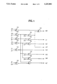
- FIG. 1 is a logic circuit diagram of a conversion circuit for converting to the elements over GF(2 4 ) according to the present invention.
- FIG. 2 is a logic circuit diagram of a reversion circuit for reverting to the elements over GF(2 8 ) according to the present invention.
- FIG. 3 is a block diagram of a multiplier using a subfield GF(2 4 ) according to the present invention.
- FIG. 4 is a block diagram of an inversion circuit using a subfield GF(2 4 ) according to the present invention.
- FIG. 5 is a block diagram of a divider using a subfield GF(2 4 ) according to the present invention.
- FIG. 6 is a logic circuit diagram of a multiplier over GF(2 4 ) according to the present invention.
- FIG. 7 is a logic circuit diagram of an inversion circuit over GF(2 4 ) according to the present invention.
- FIG. 8 is a logic circuit diagram of a square and ⁇ multiplier over GF(2 4 ) according to the present invention.
- FIG. 9 is a logic circuit diagram of a ⁇ multiplier over GF(2 4 ) according to the present invention.
- the operational method and circuit over GF(2 8 ) using a subfield GF(2 4 ) as an embodiment of the present invention are as follows.
- a subfield GF(2 4 ) of GF(2 8 ) is used and a basis over a subfield GF(2 4 ) of GF(2 8 ) is defined as ⁇ 1, ⁇ , where ⁇ GF(2 8 ).
- ⁇ is ⁇ 7 .
- ⁇ 1, ⁇ , ⁇ 2 , ⁇ 3 , ⁇ , ⁇ , ⁇ 2 , ⁇ 3 ⁇ ⁇ 1, ⁇ 11 9, ⁇ 2 3 8, ⁇ 1 0 2, ⁇ 7 , ⁇ 12 6, ⁇ 2 4 5, ⁇ 1 0 9 ⁇
- FIG. 1 shows a logic circuit diagram for implementing the equation (2) by using thirteen XOR gates 10.
- FIG. 2 shows a logic circuit diagram for implementing the equations (3) which uses thirteen XOR gates 10.
- element C is the product of the elements A and B. This can be represented as: ##EQU4## where a 0 , a 1 , b 0 , b 1 , c 0 , c 1 ⁇ GF(2 4 ).
- c 0 and c 1 are represented as:
- FIG. 3 shows a block diagram for implementing the equations (4) by using three multiplies over GF(2 4 ) 50, four adders over GF(2 4 ) 40, and a ⁇ multiplier over GF(2 4 ) 60.
- FIG. 4 shows a block diagram for implementing the equation (7) by using three multipliers over GF(2 4 ) 50, an adder over GF(2 4 ) 40, a square and ⁇ multiplier over GF(2 4 ) 70, and an inversion circuit over GF(2 4 ) 80.
- FIG. 5 shows a block diagram for implementing the equations (8) by using six multipliers over GF(2 4 ) 50, five adders over GF(2 4 ) 40, an inversion circuit over GF(2 4 ) 80, a ⁇ multiplier 60, and a square and ⁇ multiplier over GF(2 4 ) 70.
- Steps for the implementation of a multiplier, an inversion circuit, a square and ⁇ multiplier, and ⁇ multiplier over GF(2 4 ) which constitute the apparatuses shown in FIGS. 3, 4, 5 are as follows.
- FIG. 6 shows a logic circuit diagram for implementing the equations (9) by using sixteen AND gates 20 and fifteen XOR gates 10.
- FIG. 7 shows a logic circuit diagram for implementing the equation (10) by using sixteen AND gates 20, ten OR gates 30, and four inverters which are unshown and corresponding to a 0 through a 3 .
- FIG. 8 shows a logic circuit diagram for implementing the equation by using three XOR gates 10.
- ⁇ A is represented by a 3 +a 0 ⁇ +a 1 ⁇ 2 +(a 2 +a 3 ) ⁇ 3 .
- FIG. 9 shows a logic circuit diagram for implementing the equation by using one XOR gate 10.
- the total numbers of gates used in the multiplier, the divider, and the inversion circuit will be calculated.
- the multiplier, the divider, and the inversion circuit over GF(2 8 ) using the subfield GF(2 4 ) must have the circuits of FIGS. 1 and 2 basically.
- the present invention simplifies the circuit and performs high speed operation by decreasing the number of logic gates.
- the circuit of the present invention can be applied to the multiplier, the divider, and the inversion circuit, over GF(2 m ) where m is more than 8 or less. Also, the conversion and reversion process of the elements over GF(2 m ) can be more than once.
Landscapes
- Engineering & Computer Science (AREA)
- Physics & Mathematics (AREA)
- Theoretical Computer Science (AREA)
- General Physics & Mathematics (AREA)
- Mathematical Physics (AREA)
- Pure & Applied Mathematics (AREA)
- Mathematical Analysis (AREA)
- Mathematical Optimization (AREA)
- Computational Mathematics (AREA)
- Probability & Statistics with Applications (AREA)
- Computing Systems (AREA)
- General Engineering & Computer Science (AREA)
- Signal Processing (AREA)
- Algebra (AREA)
- Complex Calculations (AREA)
Abstract
Description
b.sub.0 =z.sub.0 +z.sub.1 +z.sub.2 +z.sub.6 +z.sub.7
b.sub.1 =z.sub.1 +z.sub.2 +z.sub.5
b.sub.2 =z.sub.3 +z.sub.5 +z.sub.7
b.sub.3 =z.sub.2 +z.sub.6 +z.sub.7
b.sub.4 =z.sub.1 +z.sub.7
b.sub.5 =z.sub.5 +z.sub.6 +z.sub.7
b.sub.6 =z.sub.3 +z.sub.5 +z.sub.6
b.sub.7 =z.sub.1 +z.sub.4 +z.sub.6 +z.sub.7 (2)
z.sub.0 =b.sub.0 +b.sub.1 +b.sub.5
z.sub.1 =b.sub.1 +b.sub.3 +b.sub.5
z.sub.2 =b.sub.2 +b.sub.3 +b.sub.6
z.sub.3 =b.sub.1 +b.sub.3 +b.sub.4 +b.sub.6
z.sub.4 =b.sub.1 +b.sub.2 +b.sub.3 +b.sub.5 +b.sub.6 +b.sub.7
z.sub.5 =b.sub.2 +b.sub.5 +b.sub.6
z.sub.6 =b.sub.1 +b.sub.2 +b.sub.3 +b.sub.4 +b.sub.5 +b.sub.6
z.sub.7 =b.sub.1 +b.sub.3 +b.sub.4 +b.sub.5 (3)
c.sub.0 =a.sub.0 b.sub.0 +a.sub.1 b.sub.1 γ
c.sub.1 =a.sub.0 b.sub.1 +a.sub.1 b.sub.0 +a.sub.1 b.sub.1 (4)
Z=x.sub.0 +x.sub.1 β
Z.sup.-1 =y.sub.0 +y.sub.1 β
Z.Z.sup.-1 =(x.sub.0 y.sub.0 +x.sub.1 γy.sub.1)+(x.sub.1 y.sub.0 +(x.sub.0 +x.sub.1)y.sub.1)β=1
______________________________________
ii) Suppose that the inverse of element A is I,
the inversion table is as follows.
a.sub.0   a.sub.1 a.sub.2
                        a.sub.3
                              I.sub.0
                                  I.sub.1
                                        I.sub.2
                                            I.sub.3
______________________________________
1       1     0       0   0     1   0     0   0
γ 0     1       0   0     0   0     1   1
γ.sup.2
        0     0       1   0     0   1     1   0
γ.sup.3
        0     0       0   1     1   1     0   0
γ.sup.4
        1     0       0   1     1   0     1   1
γ.sup.5
        1     1       0   1     0   1     0   1
γ.sup.6
        1     1       1   1     1   0     1   0
γ.sup.7
        1     1       1   0     0   1     1   1
γ.sup.8
        0     1       1   1     1   1     1   0
γ.sup.9
        1     0       1   0     1   1     1   1
γ.sup.10
        0     1       0   1     1   1     0   1
γ.sup.11
        1     0       1   1     1   0     0   1
γ.sup.12
        1     1       0   0     0   0     0   1
γ.sup.13
        0     1       1   0     0   0     1   0
γ.sup.14
        0     0       1   1     0   1     0   0
______________________________________
I.sub.0 =a.sub.0 a.sub.1 +a.sub.0 a.sub.2 a.sub.3 +a.sub.1 a.sub.2 a.sub.3
I.sub.1 =a.sub.0 a.sub.3 +a.sub.1 a.sub.2 a.sub.3 +a.sub.0 a.sub.1 a.sub.2 +a.sub.0 a.sub.2 a.sub.3
I.sub.2 =a.sub.1 a.sub.2 +a.sub.2 a.sub.3 +a.sub.0 a.sub.1 a.sub.3 +a.sub.0 a.sub.1 a.sub.2 a.sub.3
I.sub.3 =a.sub.1 a.sub.2 +a.sub.0 a.sub.1 a.sub.3 +a.sub.0 a.sub.2 a.sub.3( 10)
______________________________________
            AND gate XOR gate
______________________________________
GF(2.sup.8)              13
 →GF(2.sup.4)
three multi-  16 × 3 = 48
                         16 × 3 = 45
pliers
γ multiplier        1
four adders               4 × 4 = 16
GF(2.sup.4)              13
 →GF(2.sup.8)
              48         88
______________________________________
______________________________________
                           OR
       AND gate XOR gate   gate    NOT gate
______________________________________
GF(2.sup.8)         13
 →GF(2.sup.4)
three multi-
         16 × 3 = 48
                    15 × 3 = 45
pliers
inversion                      10    4
circuit
a square and         3
γ multiplier
two adders          4 × 2 = 8
GF(2.sup.4)         13
 →GF(2.sup.8)
         64         82         10    4
______________________________________
______________________________________
                           OR
       AND gate XOR gate   gate    NOT gate
______________________________________
GF(2.sup.8)         13
 →GF(2.sup.4)
six multi-
         16 × 6 = 96
                    15 × 6 = 90
pliers
five adders          4 × 5 = 20
γ multiplier   1
inversion
         16                    10    4
circuit
a square and         3
γ multiplier
GF(2.sup.4)         13
 →GF(2.sup.8)
         112        140        10    4
______________________________________
Claims (15)
z.sub.0 =b.sub.0 +b.sub.1 +b.sub.5
z.sub.1 =b.sub.1 +b.sub.3 +b.sub.5
z.sub.2 =b.sub.2 +b.sub.3 +b.sub.6
z.sub.3 =b.sub.1 +b.sub.3 +b.sub.4 +b.sub.6
z.sub.4 =b.sub.1 +b.sub.2 +b.sub.3 +b.sub.5 +b.sub.6 +b.sub.7
z.sub.5 =b.sub.2 +b.sub.5 +b.sub.6
z.sub.6 =b.sub.1 +b.sub.2 +b.sub.3 +b.sub.4 +b.sub.5 +b.sub.6
z.sub.7 =b.sub.1 +b.sub.3 +b.sub.4 +b.sub.5
b.sub.0 =z.sub.0 +z.sub.1 +z.sub.2 +z.sub.6 +z.sub.7
b.sub.1 =z.sub.1 +z.sub.2 +z.sub.5
b.sub.2 =z.sub.3 +z.sub.5 +z.sub.7
b.sub.3 =z.sub.2 +z.sub.6 +z.sub.7
b.sub.4 =z.sub.1 +z.sub.7
b.sub.5 =z.sub.5 +z.sub.6 +z.sub.7
b.sub.6 =z.sub.3 +z.sub.5 +z.sub.6
b.sub.7 =z.sub.1 +z.sub.4 +z.sub.6 +z.sub.7
z.sub.0 =x.sub.0 y.sub.0 +x.sub.3 y.sub.1 +(x.sub.2 +x.sub.3)y.sub.2 +(x.sub.1 +x.sub.2 +x.sub.3)y.sub.3
z.sub.1 =x.sub.1 y.sub.0 +x.sub.0 y.sub.1 +x.sub.3 y.sub.2 +(x.sub.2 +x.sub.3)y.sub.3
z.sub.2 =x.sub.2 y.sub.0 +x.sub.1 y.sub.1 +x.sub.0 y.sub.2 +x.sub.3 y.sub.3
z.sub.3 =x.sub.3 y.sub.0 +(x.sub.2 +y.sub.3)y.sub.1 +(x.sub.1 +x.sub.2 +x.sub.3)y.sub.2 +(x.sub.0 +x.sub.1 +x.sub.3)y.sub.3
I.sub.0 =a.sub.0 a.sub.1 +a.sub.0 a.sub.2 a.sub.3 +a.sub.1 a.sub.2 a.sub.3
I.sub.1 =a.sub.0 a.sub.3 +a.sub.1 a.sub.2 a.sub.3 +a.sub.0 a.sub.1 a.sub.2 +a.sub.0 a.sub.2 a.sub.3
I.sub.2 =a.sub.1 a.sub.2 +a.sub.2 a.sub.3 +a.sub.0 a.sub.1 a.sub.3 +a.sub.0 a.sub.1 a.sub.2 a.sub.3
I.sub.3 =a.sub.1 a.sub.2 +a.sub.0 a.sub.1 a.sub.3 +a.sub.0 a.sub.2 a.sub.3
c.sub.0 =a.sub.2 +a.sub.3
c.sub.1 =a.sub.0 +a.sub.2 +a.sub.3
c.sub.0 =a.sub.3
c.sub.3 =a.sub.1 +a.sub.2
d.sub.0 =a.sub.3
d.sub.1 =a.sub.0
d.sub.2 =a.sub.1
d.sub.3 =a.sub.2 +a.sub.3
z.sub.0 =b.sub.0 +b.sub.1 +b.sub.5
z.sub.1 =b.sub.1 +b.sub.3 +b.sub.5
z.sub.2 =b.sub.2 +b.sub.3 +b.sub.6
z.sub.3 =b.sub.1 +b.sub.3 +b.sub.4 +b.sub.6
z.sub.4 =b.sub.1 +b.sub.2 +b.sub.3 +b.sub.5 +b.sub.6 +b.sub.7
z.sub.5 =b.sub.2 +b.sub.5 +b.sub.6
z.sub.6 =b.sub.1 +b.sub.2 +b.sub.3 +b.sub.4 +b.sub.5 +b.sub.6
z.sub.7 =b.sub.1 +b.sub.3 +b.sub.4 +b.sub.5
b.sub.0 =z.sub.0 +z.sub.1 +z.sub.2 +z.sub.6 +z.sub.7
b.sub.1 =z.sub.1 +z.sub.2 +z.sub.5
b.sub.2 =z.sub.3 +z.sub.5 +z.sub.7
b.sub.3 =z.sub.2 +z.sub.6 +z.sub.7
b.sub.4 =z.sub.1 +z.sub.7
b.sub.5 =z.sub.5 +z.sub.6 +z.sub.7
b.sub.6 =z.sub.3 +z.sub.5 +z.sub.6
b.sub.7 =z.sub.1 +z.sub.4 +z.sub.6 +z.sub.7
z.sub.0 =x.sub.0 y.sub.0 +x.sub.3 y.sub.1 +(x.sub.2 +x.sub.3)y.sub.2 +(x.sub.1 +x.sub.2 +x.sub.3)y.sub.3
z.sub.1 =x.sub.1 y.sub.0 +x.sub.0 y.sub.1 +x.sub.3 y.sub.2 +(x.sub.2 +x.sub.3)y.sub.3
z.sub.2 =x.sub.2 y.sub.0 +x.sub.1 y.sub.1 +x.sub.0 y.sub.2 +x.sub.3 y.sub.3
z.sub.3 =x.sub.3 y.sub.0 +(x.sub.2 +y.sub.3)y.sub.1 +(x.sub.1 +x.sub.2 +x.sub.3)y.sub.2 +(x.sub.0 +x.sub.1 +x.sub.3)y.sub.3
I.sub.0 =a.sub.0 a.sub.1 +a.sub.0 a.sub.2 a.sub.3 +a.sub.1 a.sub.2 a.sub.3
I.sub.1 =a.sub.0 a.sub.3 +a.sub.1 a.sub.2 a.sub.3 +a.sub.0 a.sub.1 a.sub.2 +a.sub.0 a.sub.2 a.sub.3
I.sub.2 =a.sub.1 a.sub.2 +a.sub.2 a.sub.3 +a.sub.0 a.sub.1 a.sub.3 +a.sub.0 a.sub.1 a.sub.2 a.sub.3
I.sub.3 =a.sub.1 a.sub.2 +a.sub.0 a.sub.1 a.sub.3 +a.sub.0 a.sub.0 a.sub.2 a.sub.3
c.sub.0 =a.sub.2 +a.sub.3
c.sub.1 =a.sub.0 +a.sub.2 +a.sub.3
c.sub.0 =a.sub.3
c.sub.3 =a.sub.1 +a.sub.2
d.sub.0 =a.sub.3
d.sub.1 =a.sub.0
d.sub.2 =a.sub.1
d.sub.3 =a.sub.2 +a.sub.3
Applications Claiming Priority (2)
| Application Number | Priority Date | Filing Date | Title |
|---|---|---|---|
| KR1019910004391A KR940001147B1 (en) | 1991-03-20 | 1991-03-20 | OPERATING METHOD AND APPARATUS FOR GF(2m) |
| KR91-4391 | 1991-03-30 |
Publications (1)
| Publication Number | Publication Date |
|---|---|
| US5227992A true US5227992A (en) | 1993-07-13 |
Family
ID=19312264
Family Applications (1)
| Application Number | Title | Priority Date | Filing Date |
|---|---|---|---|
| US07/717,506 Expired - Lifetime US5227992A (en) | 1991-03-20 | 1991-06-19 | Operational method and apparatus over GF(2m) using a subfield GF(2.sup. |
Country Status (5)
| Country | Link |
|---|---|
| US (1) | US5227992A (en) |
| JP (1) | JPH0728782A (en) |
| KR (1) | KR940001147B1 (en) |
| CN (1) | CN1042270C (en) |
| GB (1) | GB2253975B (en) |
Cited By (12)
| Publication number | Priority date | Publication date | Assignee | Title |
|---|---|---|---|---|
| US5771184A (en) * | 1995-10-12 | 1998-06-23 | Adaptec, Inc. | System and method for solving quadratic equation in galois fields |
| US5812438A (en) * | 1995-10-12 | 1998-09-22 | Adaptec, Inc. | Arithmetic logic unit and method for numerical computations in galois fields |
| US5854759A (en) * | 1997-05-05 | 1998-12-29 | Rsa Data Security, Inc. | Methods and apparatus for efficient finite field basis conversion |
| US6003057A (en) * | 1997-12-24 | 1999-12-14 | Motorola, Inc. | Galois field arithmetic logic unit circuit |
| US6141786A (en) * | 1998-06-04 | 2000-10-31 | Intenational Business Machines Corporation | Method and apparatus for performing arithmetic operations on Galois fields and their extensions |
| EP0832520A4 (en) * | 1995-06-14 | 2001-02-07 | Quantum Corp | Dedicated alu architecture for 10-bit reed-solomon error correction module |
| US6286022B1 (en) | 1997-11-18 | 2001-09-04 | Rsa Security Inc. | Efficient finite field basis conversion involving a dual basis |
| US6466959B2 (en) * | 1998-06-25 | 2002-10-15 | Hewlett Packard Co | Apparatus and method for efficient arithmetic in finite fields through alternative representation |
| US20040225701A1 (en) * | 2003-05-06 | 2004-11-11 | Gashkov Sergei B. | Method for constructing logic circuits of small depth and complexity for operation of inversion in finite fields of characteristic 2 |
| US20050086278A1 (en) * | 2003-10-16 | 2005-04-21 | Samsung Electronics Co., Ltd. | Method and apparatus for performing multiplication in finite field GF(2n) |
| US7424504B2 (en) | 1997-04-18 | 2008-09-09 | Certicom Corp. | Arithmetic processor for accomodating different field sizes |
| US8649511B2 (en) | 2009-06-22 | 2014-02-11 | Realtek Semiconductor Corp. | Method and processing circuit for dealing with galois field computation |
Families Citing this family (6)
| Publication number | Priority date | Publication date | Assignee | Title |
|---|---|---|---|---|
| KR20030020496A (en) * | 2001-08-29 | 2003-03-10 | 강경식 | A Serial Multiplier over the Subfields GF(2^8) of Galois field GF(2^4) |
| KR20030020495A (en) * | 2001-08-29 | 2003-03-10 | 강경식 | A Serial Multiplier over the Subfields GF(2^16) of Galois field GF(2^4) |
| KR20030020492A (en) * | 2001-08-29 | 2003-03-10 | 강경식 | A Serial Multiplier over the Subfields GF(2^8) of Galois field GF(2^2) |
| KR100486726B1 (en) * | 2002-11-09 | 2005-05-03 | 삼성전자주식회사 | Method and Apparatus for basis conversion in a finite field |
| CN103729162A (en) * | 2012-10-15 | 2014-04-16 | 北京兆易创新科技股份有限公司 | Galois field operating system and method |
| US9740456B2 (en) * | 2015-04-23 | 2017-08-22 | Altera Corporation | Circuitry and methods for implementing Galois-field reduction |
Citations (6)
| Publication number | Priority date | Publication date | Assignee | Title |
|---|---|---|---|---|
| US4162480A (en) * | 1977-01-28 | 1979-07-24 | Cyclotomics, Inc. | Galois field computer |
| US4251875A (en) * | 1979-02-12 | 1981-02-17 | Sperry Corporation | Sequential Galois multiplication in GF(2n) with GF(2m) Galois multiplication gates |
| US4847801A (en) * | 1987-10-26 | 1989-07-11 | Cyclotomics, Inc. | Compact galois field multiplier |
| US4949294A (en) * | 1987-10-30 | 1990-08-14 | Thomson-Csf | Computation circuit using residual arithmetic |
| US4975867A (en) * | 1987-06-26 | 1990-12-04 | Digital Equipment Corporation | Apparatus for dividing elements of a Galois Field GF (2QM) |
| US4989171A (en) * | 1988-10-18 | 1991-01-29 | U.S. Philips Corporation | Data processing method and apparatus for calculating a multiplicatively inverted element of a finite field |
Family Cites Families (8)
| Publication number | Priority date | Publication date | Assignee | Title |
|---|---|---|---|---|
| JPS57155667A (en) * | 1981-03-23 | 1982-09-25 | Sony Corp | Arithmetic circuit of galois matter |
| JPS58219852A (en) * | 1982-06-15 | 1983-12-21 | Toshiba Corp | Correcting circuit of error |
| EP0096163B1 (en) * | 1982-06-15 | 1988-06-01 | Kabushiki Kaisha Toshiba | Apparatus for dividing the elements of a galois field |
| DE3377029D1 (en) * | 1982-06-15 | 1988-07-14 | Toshiba Kk | Apparatus for dividing the elements of a galois field |
| FR2605818B1 (en) * | 1986-10-27 | 1992-09-18 | Thomson Csf | ALGEBRICAL ENCODER-DECODER OF REED SOLOMON AND BCH BLOCK CODES, APPLICABLE TO DIGITAL TELECOMMUNICATIONS |
| US4875211A (en) * | 1986-12-10 | 1989-10-17 | Matsushita Electric Industrial Co., Ltd. | Galois field arithmetic logic unit |
| JP2641285B2 (en) * | 1988-05-23 | 1997-08-13 | 三菱電機株式会社 | Galois field division circuit and multiplication / division shared circuit |
| JPH02217022A (en) * | 1989-02-17 | 1990-08-29 | Matsushita Electric Ind Co Ltd | Galois field computing element |
-
1991
- 1991-03-20 KR KR1019910004391A patent/KR940001147B1/en not_active Expired - Lifetime
- 1991-06-19 US US07/717,506 patent/US5227992A/en not_active Expired - Lifetime
- 1991-06-20 CN CN91104744A patent/CN1042270C/en not_active Expired - Lifetime
- 1991-08-05 JP JP3195580A patent/JPH0728782A/en active Pending
- 1991-08-29 GB GB9118522A patent/GB2253975B/en not_active Expired - Lifetime
Patent Citations (6)
| Publication number | Priority date | Publication date | Assignee | Title |
|---|---|---|---|---|
| US4162480A (en) * | 1977-01-28 | 1979-07-24 | Cyclotomics, Inc. | Galois field computer |
| US4251875A (en) * | 1979-02-12 | 1981-02-17 | Sperry Corporation | Sequential Galois multiplication in GF(2n) with GF(2m) Galois multiplication gates |
| US4975867A (en) * | 1987-06-26 | 1990-12-04 | Digital Equipment Corporation | Apparatus for dividing elements of a Galois Field GF (2QM) |
| US4847801A (en) * | 1987-10-26 | 1989-07-11 | Cyclotomics, Inc. | Compact galois field multiplier |
| US4949294A (en) * | 1987-10-30 | 1990-08-14 | Thomson-Csf | Computation circuit using residual arithmetic |
| US4989171A (en) * | 1988-10-18 | 1991-01-29 | U.S. Philips Corporation | Data processing method and apparatus for calculating a multiplicatively inverted element of a finite field |
Non-Patent Citations (2)
| Title |
|---|
| Itoh et al., "Effective Recursive Algorithm for Computing Multiplicative Inverses in GF(2m)", Electronics Letters, Mar. 17th, 1988, vol. 24, No. 6, pp. 334-335. |
| Itoh et al., Effective Recursive Algorithm for Computing Multiplicative Inverses in GF(2 m ) , Electronics Letters, Mar. 17th, 1988, vol. 24, No. 6, pp. 334 335. * |
Cited By (15)
| Publication number | Priority date | Publication date | Assignee | Title |
|---|---|---|---|---|
| EP0832520A4 (en) * | 1995-06-14 | 2001-02-07 | Quantum Corp | Dedicated alu architecture for 10-bit reed-solomon error correction module |
| US5812438A (en) * | 1995-10-12 | 1998-09-22 | Adaptec, Inc. | Arithmetic logic unit and method for numerical computations in galois fields |
| US5771184A (en) * | 1995-10-12 | 1998-06-23 | Adaptec, Inc. | System and method for solving quadratic equation in galois fields |
| US6101520A (en) * | 1995-10-12 | 2000-08-08 | Adaptec, Inc. | Arithmetic logic unit and method for numerical computations in Galois fields |
| US7424504B2 (en) | 1997-04-18 | 2008-09-09 | Certicom Corp. | Arithmetic processor for accomodating different field sizes |
| US5854759A (en) * | 1997-05-05 | 1998-12-29 | Rsa Data Security, Inc. | Methods and apparatus for efficient finite field basis conversion |
| US6286022B1 (en) | 1997-11-18 | 2001-09-04 | Rsa Security Inc. | Efficient finite field basis conversion involving a dual basis |
| US6003057A (en) * | 1997-12-24 | 1999-12-14 | Motorola, Inc. | Galois field arithmetic logic unit circuit |
| US6141786A (en) * | 1998-06-04 | 2000-10-31 | Intenational Business Machines Corporation | Method and apparatus for performing arithmetic operations on Galois fields and their extensions |
| US6466959B2 (en) * | 1998-06-25 | 2002-10-15 | Hewlett Packard Co | Apparatus and method for efficient arithmetic in finite fields through alternative representation |
| US20040225701A1 (en) * | 2003-05-06 | 2004-11-11 | Gashkov Sergei B. | Method for constructing logic circuits of small depth and complexity for operation of inversion in finite fields of characteristic 2 |
| US7167886B2 (en) * | 2003-05-06 | 2007-01-23 | Lsi Logic Corporation | Method for constructing logic circuits of small depth and complexity for operation of inversion in finite fields of characteristic 2 |
| US20050086278A1 (en) * | 2003-10-16 | 2005-04-21 | Samsung Electronics Co., Ltd. | Method and apparatus for performing multiplication in finite field GF(2n) |
| US7539719B2 (en) * | 2003-10-16 | 2009-05-26 | Samsung Electronics Co., Ltd. | Method and apparatus for performing multiplication in finite field GF(2n) |
| US8649511B2 (en) | 2009-06-22 | 2014-02-11 | Realtek Semiconductor Corp. | Method and processing circuit for dealing with galois field computation |
Also Published As
| Publication number | Publication date |
|---|---|
| CN1042270C (en) | 1999-02-24 |
| GB2253975B (en) | 1994-05-25 |
| GB2253975A (en) | 1992-09-23 |
| JPH0728782A (en) | 1995-01-31 |
| CN1059042A (en) | 1992-02-26 |
| GB9118522D0 (en) | 1991-10-16 |
| KR920019108A (en) | 1992-10-22 |
| KR940001147B1 (en) | 1994-02-14 |
Similar Documents
| Publication | Publication Date | Title |
|---|---|---|
| US5227992A (en) | Operational method and apparatus over GF(2m) using a subfield GF(2.sup. | |
| US4918638A (en) | Multiplier in a galois field | |
| Wang et al. | VLSI architectures for computing multiplications and inverses in GF (2 m) | |
| US4797848A (en) | Pipelined bit-serial Galois Field multiplier | |
| US3648038A (en) | Apparatus and method for obtaining the reciprocal of a number and the quotient of two numbers | |
| KR100309724B1 (en) | Reed solomon coding apparatus and reed solomon coding method | |
| US4994995A (en) | Bit-serial division method and apparatus | |
| US3997770A (en) | Recursive digital filter | |
| US5272661A (en) | Finite field parallel multiplier | |
| KR100322739B1 (en) | Finite Field Computation Method and Its Apparatus | |
| US4216531A (en) | Finite field multiplier | |
| US4856004A (en) | Microprocessor based BCH decoder | |
| US4215417A (en) | Two-term vector multiplier | |
| JP3351413B2 (en) | Parallel processing Reed-Solomon encoding circuit and parallel processing Reed-Solomon encoding method used therefor | |
| US6138134A (en) | Computational method and apparatus for finite field multiplication | |
| US5150321A (en) | Apparatus for performing serial binary multiplication | |
| US5448510A (en) | Method and apparatus for producing the reciprocal of an arbitrary element in a finite field | |
| US4760549A (en) | In line testing device for a circuit calculating the discrete Fourier transform and a circuit comprising such a device | |
| Tanaka et al. | Novel binary signed-digit addition algorithm for FPGA implementation | |
| JPS63107319A (en) | Polynomial division circuit on extended Galois field | |
| US5309385A (en) | Vector division processing method and system | |
| US3805042A (en) | Multiplication of a binary-coded number having an even radix with a factor equal to half the radix | |
| Hagglund et al. | A polynomial-based division algorithm | |
| JPH0554160A (en) | Function generating method and general function generator for its method | |
| Pratt | Fast pseudo-random number generators for computers |
Legal Events
| Date | Code | Title | Description |
|---|---|---|---|
| AS | Assignment |
Owner name: SAMSUNG ELECTRONICS CO., LTD. Free format text: ASSIGNMENT OF ASSIGNORS INTEREST.;ASSIGNOR:YEOM, HEUNG-YEOL;REEL/FRAME:005750/0869 Effective date: 19910530 Owner name: SAMSUNG ELECTRONICS CO., LTD. Free format text: ASSIGNMENT OF ASSIGNORS INTEREST.;ASSIGNORS:LEE, MAN-YOUNG;KIM, JAE-MUN;PARK, HAK-SONG;AND OTHERS;REEL/FRAME:005750/0867 Effective date: 19910530 |
|
| STCF | Information on status: patent grant |
Free format text: PATENTED CASE |
|
| CC | Certificate of correction | ||
| FPAY | Fee payment |
Year of fee payment: 4 |
|
| FEPP | Fee payment procedure |
Free format text: PAYOR NUMBER ASSIGNED (ORIGINAL EVENT CODE: ASPN); ENTITY STATUS OF PATENT OWNER: LARGE ENTITY |
|
| FPAY | Fee payment |
Year of fee payment: 8 |
|
| FPAY | Fee payment |
Year of fee payment: 12 |