US5221095A - Static and dynamic shaft seal assembly - Google Patents
Static and dynamic shaft seal assembly Download PDFInfo
- Publication number
- US5221095A US5221095A US07/772,233 US77223391A US5221095A US 5221095 A US5221095 A US 5221095A US 77223391 A US77223391 A US 77223391A US 5221095 A US5221095 A US 5221095A
- Authority
- US
- United States
- Prior art keywords
- rotor
- stator
- seal member
- housing
- shaft
- Prior art date
- Legal status (The legal status is an assumption and is not a legal conclusion. Google has not performed a legal analysis and makes no representation as to the accuracy of the status listed.)
- Expired - Lifetime
Links
- 230000003068 static effect Effects 0.000 title description 9
- 239000007787 solid Substances 0.000 claims abstract description 13
- 238000007789 sealing Methods 0.000 claims description 21
- 239000012530 fluid Substances 0.000 claims description 12
- 239000000314 lubricant Substances 0.000 claims description 7
- 238000000034 method Methods 0.000 claims description 7
- 239000000356 contaminant Substances 0.000 claims description 6
- 230000013011 mating Effects 0.000 claims description 6
- 239000000463 material Substances 0.000 claims description 5
- 229920001971 elastomer Polymers 0.000 claims description 3
- 239000000806 elastomer Substances 0.000 claims description 3
- 238000005461 lubrication Methods 0.000 claims 1
- 229920001084 poly(chloroprene) Polymers 0.000 claims 1
- 238000011144 upstream manufacturing Methods 0.000 claims 1
- 210000003027 ear inner Anatomy 0.000 description 5
- 239000003921 oil Substances 0.000 description 5
- XLYOFNOQVPJJNP-UHFFFAOYSA-N water Substances O XLYOFNOQVPJJNP-UHFFFAOYSA-N 0.000 description 5
- 239000000428 dust Substances 0.000 description 4
- 230000005540 biological transmission Effects 0.000 description 3
- 238000011109 contamination Methods 0.000 description 3
- 230000001050 lubricating effect Effects 0.000 description 2
- 229910000906 Bronze Inorganic materials 0.000 description 1
- 229920002449 FKM Polymers 0.000 description 1
- 229910000831 Steel Inorganic materials 0.000 description 1
- 230000015572 biosynthetic process Effects 0.000 description 1
- 239000010974 bronze Substances 0.000 description 1
- KUNSUQLRTQLHQQ-UHFFFAOYSA-N copper tin Chemical compound [Cu].[Sn] KUNSUQLRTQLHQQ-UHFFFAOYSA-N 0.000 description 1
- 230000000694 effects Effects 0.000 description 1
- 238000005755 formation reaction Methods 0.000 description 1
- 238000009472 formulation Methods 0.000 description 1
- 239000004519 grease Substances 0.000 description 1
- 239000010687 lubricating oil Substances 0.000 description 1
- 238000004519 manufacturing process Methods 0.000 description 1
- 239000002184 metal Substances 0.000 description 1
- 239000000203 mixture Substances 0.000 description 1
- 238000012986 modification Methods 0.000 description 1
- 230000004048 modification Effects 0.000 description 1
- 150000002825 nitriles Chemical class 0.000 description 1
- 239000002245 particle Substances 0.000 description 1
- 239000004033 plastic Substances 0.000 description 1
- 230000002028 premature Effects 0.000 description 1
- 239000011435 rock Substances 0.000 description 1
- 239000010959 steel Substances 0.000 description 1
- 239000000126 substance Substances 0.000 description 1
- 238000013022 venting Methods 0.000 description 1
Images

Classifications
-
- F—MECHANICAL ENGINEERING; LIGHTING; HEATING; WEAPONS; BLASTING
- F16—ENGINEERING ELEMENTS AND UNITS; GENERAL MEASURES FOR PRODUCING AND MAINTAINING EFFECTIVE FUNCTIONING OF MACHINES OR INSTALLATIONS; THERMAL INSULATION IN GENERAL
- F16J—PISTONS; CYLINDERS; SEALINGS
- F16J15/00—Sealings
- F16J15/002—Sealings comprising at least two sealings in succession
- F16J15/008—Sealings comprising at least two sealings in succession with provision to put out of action at least one sealing; One sealing sealing only on standstill; Emergency or servicing sealings
-
- F—MECHANICAL ENGINEERING; LIGHTING; HEATING; WEAPONS; BLASTING
- F16—ENGINEERING ELEMENTS AND UNITS; GENERAL MEASURES FOR PRODUCING AND MAINTAINING EFFECTIVE FUNCTIONING OF MACHINES OR INSTALLATIONS; THERMAL INSULATION IN GENERAL
- F16J—PISTONS; CYLINDERS; SEALINGS
- F16J15/00—Sealings
- F16J15/16—Sealings between relatively-moving surfaces
- F16J15/164—Sealings between relatively-moving surfaces the sealing action depending on movements; pressure difference, temperature or presence of leaking fluid
-
- F—MECHANICAL ENGINEERING; LIGHTING; HEATING; WEAPONS; BLASTING
- F16—ENGINEERING ELEMENTS AND UNITS; GENERAL MEASURES FOR PRODUCING AND MAINTAINING EFFECTIVE FUNCTIONING OF MACHINES OR INSTALLATIONS; THERMAL INSULATION IN GENERAL
- F16J—PISTONS; CYLINDERS; SEALINGS
- F16J15/00—Sealings
- F16J15/44—Free-space packings
- F16J15/447—Labyrinth packings
- F16J15/4472—Labyrinth packings with axial path
- F16J15/4474—Pre-assembled packings
-
- F—MECHANICAL ENGINEERING; LIGHTING; HEATING; WEAPONS; BLASTING
- F16—ENGINEERING ELEMENTS AND UNITS; GENERAL MEASURES FOR PRODUCING AND MAINTAINING EFFECTIVE FUNCTIONING OF MACHINES OR INSTALLATIONS; THERMAL INSULATION IN GENERAL
- F16C—SHAFTS; FLEXIBLE SHAFTS; ELEMENTS OR CRANKSHAFT MECHANISMS; ROTARY BODIES OTHER THAN GEARING ELEMENTS; BEARINGS
- F16C19/00—Bearings with rolling contact, for exclusively rotary movement
- F16C19/02—Bearings with rolling contact, for exclusively rotary movement with bearing balls essentially of the same size in one or more circular rows
- F16C19/10—Bearings with rolling contact, for exclusively rotary movement with bearing balls essentially of the same size in one or more circular rows for axial load mainly
-
- F—MECHANICAL ENGINEERING; LIGHTING; HEATING; WEAPONS; BLASTING
- F16—ENGINEERING ELEMENTS AND UNITS; GENERAL MEASURES FOR PRODUCING AND MAINTAINING EFFECTIVE FUNCTIONING OF MACHINES OR INSTALLATIONS; THERMAL INSULATION IN GENERAL
- F16C—SHAFTS; FLEXIBLE SHAFTS; ELEMENTS OR CRANKSHAFT MECHANISMS; ROTARY BODIES OTHER THAN GEARING ELEMENTS; BEARINGS
- F16C33/00—Parts of bearings; Special methods for making bearings or parts thereof
- F16C33/72—Sealings
- F16C33/76—Sealings of ball or roller bearings
- F16C33/80—Labyrinth sealings
-
- Y—GENERAL TAGGING OF NEW TECHNOLOGICAL DEVELOPMENTS; GENERAL TAGGING OF CROSS-SECTIONAL TECHNOLOGIES SPANNING OVER SEVERAL SECTIONS OF THE IPC; TECHNICAL SUBJECTS COVERED BY FORMER USPC CROSS-REFERENCE ART COLLECTIONS [XRACs] AND DIGESTS
- Y10—TECHNICAL SUBJECTS COVERED BY FORMER USPC
- Y10S—TECHNICAL SUBJECTS COVERED BY FORMER USPC CROSS-REFERENCE ART COLLECTIONS [XRACs] AND DIGESTS
- Y10S277/00—Seal for a joint or juncture
- Y10S277/91—O-ring seal
Definitions
- This invention relates generally to mechanical equipment shaft sealing devices and more particularly concerns a shaft seal mechanism which seals effectively when a shaft is at rest, and which changes configurations so as to seal effectively but without friction when the shaft is rotating at an operating speed.
- Bearings and mechanical seals may be responsible for up to 80% of rotating equipment failures. There is a close relationship between the life of these two critical components.
- the failure of a mechanical seal may cause the bearings to fail and poor bearing conditions can reduce seal life. It is estimated that only 10% of bearings achieve their minimum design life of from 24,000 to 40,000 hours (3 to 5 years).
- Rain, product leakage, debris, and wash-down water entering the bearing housing contaminate the bearing lubricant and have a catastrophic effect on bearing life. Very small amounts of water can compromise bearing life.
- a contamination level of 0.002% water in the lubricating oil can reduce bearing life by as much as 48%. As little as 0.10% water is reported to reduce bearing life by as much as 90%.
- Auxiliary mechanical equipment shaft seals sometimes called bearing isolators or sealing rings, have become increasingly important to modern mechanical equipment, especially for equipment called upon to operate in hostile applications.
- mechanical power transmission units used in rock quarries are often subjected to highly abrasive dust particles.
- Elastomeric lip or O-ring shaft seals can quickly wear out and fail in environments such as these. Dust and exterior contaminants cannot be excluded from the interior of the transmission housing by a failed standard sealing device. Nor can oil or other fluids be prevented from leaking out of the transmission devices past a worn lip seal.
- auxiliary or improved primary sealing arrangements and devices To prevent the ingress of corruption and the egress of lubricating fluids, a number of auxiliary or improved primary sealing arrangements and devices have been provided. Some of these sealing devices provide a physical engagement of the shaft and a wiping action while the shaft operates. Other devices provide an interengagement and wiping action between seal parts. But in both such arrangements, the inevitable friction causes inevitable part wear.
- lip seals are a well-established method of protecting bearing housings from water, dust, chemical or steam contamination. Lip seals normally involve a stationary elastomeric lip or lips touching the rotating shaft or sleeve at an angle so that contaminants are excluded from the housing. While lip seals have a low initial cost, lip seals have a short protection life, approximately 3,000 hours, due to wear of the elastomer or the shaft itself.
- labyrinth device Another type of seal is a labyrinth device which contains a tortuous path that makes it difficult for contaminants to enter the bearing housing to degrade lubricant effectiveness.
- the advantages of labyrinths are their non-wearing and self-venting features.
- the hollow O-ring seal disclosed in applicant's patent 4,989,833 provides static sealing action when the shaft is at rest, and non-contact dynamic sealing action when the shaft is rotating.
- the solid O-ring seal disclosed in applicant's parent application serial number 07/624,881 also provides static sealing action when the shaft is at rest and non-contact dynamic sealing action when the shaft is rotating.
- a small percentage of these O-rings have insufficient lift-off from the stator during rotation of the shaft, such that the seal is subject to premature fatigue and failure due to heat and friction.
- Still another objective is to provide a seal of the type described which will provide a long, trouble-free service life.
- an isolator mechanism for use with a machinery housing and a rotatable shaft protruding through the housing.
- the isolator mechanism comprises a stator ring affixed to the housing and a rotor ring which is attached to the shaft.
- the stator and rotor are so shaped that the stator has a male cylindrical surface, and the rotor has a female cylindrical surface located radially outwardly of the stator male surface.
- a solid, yet stretchably deformable, annular seal member is mounted on the rotor female surface and engages the stator male surface when the rotor and seal member are at rest. However, the seal member is stretched by centrifugal force into a configuration out of engagement with the stator when the rotor and seal member are moving at operating speeds.
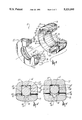
- FIG. 1 is a sectional view of a typical machinery housing, bearing, and protruding shaft upon which is mounted a novel seal of the present invention, with the shaft being at rest.
- FIG. 2 is a sectional view similar to FIG. 1 showing the seal in further detail.
- FIG. 3 is an exploded view of the seal of the present invention.
- FIG. 4 is an enlarged sectional view showing portions of seal parts as they appear when the shaft is stationary.
- FIG. 5 is an enlarged sectional view similar to FIG. 4 showing the bearing seal parts as they appear when the shaft is rotating at an operating speed.
- FIG. 1 there is shown the novel seal or bearing isolator 10 as it appears when installed on and within a housing 12.
- a rotatable shaft 13 protrudes through this seal 10 and the housing 12.
- a bearing 14 is functionally interposed between the stationary housing 12 and the rotatable shaft 13 in known manner.
- the novel seal comprises, in general, a ring-like stator 20 which is affixed to the housing 12 and a mating rotor ring 22 which is secured to the shaft 13, and which follows the rotational motion of the shaft 13.
- the rotor and stator 20 and 22 can be formed of any suitable material such as bronze, steel or plastic of an appropriate formulation.
- the stator 20 is designed and sized to fit securely by means of a light metal-to-metal interference fit within a recess 24 formed in the housing 12.
- An O-ring seal 26 of known sort provides an effective and permanent seal between the stator 20 and the housing 12 so as to exclude dust and other corruption from the outside environment E, and to inhibit or prohibit the leakage of oil or other fluid from the housing inside I.
- the stator 20 is annular in general shape, but is formed so that its inner surface 28 is generally cylindrical in shape, and is sized to provide a modest clearance between that surface 28 and the adjacent outer surface of the shaft 13.
- the stator 20 is rigidly affixed to the housing 12 but does not engage the shaft 13.
- annular fluid catchment groove 30 can be formed in the interior of the stator 20.
- the illustrated groove 30 is provided with a first or downstream face 32 oriented generally perpendicularly to the axis A of the shaft 13, and a second opposed face 34 which is conical in shape.
- This groove configuration has been found to be effective in collecting oil or other fluids which may flow along the surface of the shaft 13 in a direction leading from the interior I of the equipment housing towards the exterior environment E.
- a return or drain groove 36 located at the bottom of the stator 20 is sloped toward the shaft axis and collects the accumulated oil or other fluid and encourages its return to the interior bottom of the housing 12.
- the rotor 22 is affixed to and rotates with the shaft 13.
- the rotor 22 is provided with a restrictive recess 42 in which is mounted an O-ring 44 of known type.
- the O-ring 44 is sized and otherwise designed to be moderately compressed within the recess 42 and as to engage the shaft 13 with a modest amount of compressive pressure, in known manner.
- the rotor 22 is formed with an axially-extending flange 50, and the stator 20 is provided with a mating recess 52.
- the rotor flange 50 defines an axially-extending, cylindrical female surface 54 and the stator 20 has a mating, confronting, underlying, axially-extending surface 56. Between these surfaces 54 and 56 is interposed a solid, yet stretchable O-ring seal member 60, which engages both the stator 20 and the rotor 22 when the shaft 13 and rotor 22 are at rest.
- this stretchable seal member 60 is disposed in a recess 62 formed in the rotor flange 50, and the seal member 60 is sized and shaped so as to engage the confronting and adjacent stator male surface 56 and the opposite side walls 63 of recess 62 when the rotor 22 and shaft 13 are not in motion.
- the stator surface 56 is interrupted by a groove 64 which is axially centered relative to the recess 62. This groove 64 defines two opposed shoulders 66, 68. The shoulders 66, 68 engage the resilient seal member 60 along two opposed annular lines of contact when the rotor 22 is not in motion.
- the solid seal member 60 centrifugates away from its engagement with the stator 20 when the rotor 22 and shaft 13 are turning at an operating speed, as shown particularly in FIG. 5.
- the excessive radial depth of recess 62 allows seal 60 to expand or stretch circumferentially during rotation, so that the seal disengages from surface 56 of stator 20.
- This lift-off or seal disengagement occurs because the centrifugal force applied to and experienced by the seal member 60 causes that seal member 60 to stretch radially as the member slides along the walls 63 of the recess 62 and away from the underlying stator male surface 56, as particularly shown in FIG. 5.
- the sealing member is dynamically effective to inhibit the ingress of corruption or the egress of fluids, yet it is frictionless and does not wear in operation.
- the seal member 60 has a substantially circular cross section, both at rest and when rotated.
- the shaft When the shaft is at rest, there is, preferably and approximately, a 0.010 inch space between seal member 60 and the bottom wall 65 of recess 62.
- the gap allows a 0.010 inch lift-off of the seal member from stator surface 56, with a corresponding 0.020 inch increase in circumference of the seal member.
- a lubricant such as grease or the like, may be utilized in groove 64 so as to reduce the friction between the seal member and the stator at the initial rotational start up of shaft, before a sufficient operational speed is achieved to produce lift-off of the seal from the stator.
- this resilient seal member 60 is a solid toroid formed from a nitrile or flora-elastomer material, such as viton, which is manufactured by Du Pont.
- the seal preferably has a low durometer hardness, shore A, ranging from 40-70 so that the seal is resiliently deformable.
- the seal member 60 increasingly deforms and lifts away from engagement with the underlying stator as the centrifugal forces increase. These centrifugal forces increase in squared proportion to the linear speed of the moving sealing element 60.
- stator recess 52 additional surface formations are provided in the stator recess 52 and mating rotor flange 50 to inhibit the ingress of corruption and the egress of fluids, especially when the shaft 13 is rotating.
- the rotor flange 50 is formed so as to have a series of shoulders or corners 70-79 and annular collection grooves 80, 82.
- the stator recess 52 is likewise provided with a mating projection 84 and corners 90-94.
- These concentric stator and rotor rings define an annular, convoluted, labyrinth passage 96 of extended length and various sixes or thicknesses. This path is, at its thinnest portion, from 0.007 inches to 0.150 inches in radius or thickness.
- the labyrinth path effectively prevents lubricants from passing outwardly from the interior housing I to the exterior E, and also prevents the ingress of corruption from the exterior E of the interior I.
- a radially-inwardly extending bore 100 which communicates with this collection groove 96.
- the bore 100 leads to the outside E of the machine housing 12, and permits corruption and other materials which may have collected within the collection groove 96 to expel out of and away from the seal device 10.
- stator 20 the rotor 22 and the solid seal 60 can be accomplished quickly and easily by known methods. When assembled, the stator and rotor do not physically engage one another and are interference-free both in configuration and in dynamic operation.
Landscapes
- Engineering & Computer Science (AREA)
- General Engineering & Computer Science (AREA)
- Mechanical Engineering (AREA)
- Sealing Of Bearings (AREA)
Abstract
Description
Claims (19)
Priority Applications (1)
| Application Number | Priority Date | Filing Date | Title |
|---|---|---|---|
| US07/772,233 US5221095A (en) | 1989-06-14 | 1991-10-07 | Static and dynamic shaft seal assembly |
Applications Claiming Priority (3)
| Application Number | Priority Date | Filing Date | Title |
|---|---|---|---|
| US07/365,895 US4989883A (en) | 1989-06-14 | 1989-06-14 | Static and dynamic shaft seal assembly |
| US07/624,881 US5069461A (en) | 1989-06-14 | 1990-12-05 | Static and dynamic shaft seal assembly |
| US07/772,233 US5221095A (en) | 1989-06-14 | 1991-10-07 | Static and dynamic shaft seal assembly |
Related Parent Applications (1)
| Application Number | Title | Priority Date | Filing Date |
|---|---|---|---|
| US07/624,881 Continuation-In-Part US5069461A (en) | 1989-06-14 | 1990-12-05 | Static and dynamic shaft seal assembly |
Publications (1)
| Publication Number | Publication Date |
|---|---|
| US5221095A true US5221095A (en) | 1993-06-22 |
Family
ID=27408722
Family Applications (1)
| Application Number | Title | Priority Date | Filing Date |
|---|---|---|---|
| US07/772,233 Expired - Lifetime US5221095A (en) | 1989-06-14 | 1991-10-07 | Static and dynamic shaft seal assembly |
Country Status (1)
| Country | Link |
|---|---|
| US (1) | US5221095A (en) |
Cited By (50)
| Publication number | Priority date | Publication date | Assignee | Title |
|---|---|---|---|---|
| US5378000A (en) * | 1992-10-19 | 1995-01-03 | Inpro Companies, Inc. | Shaft seal assembly |
| US5411366A (en) * | 1991-12-04 | 1995-05-02 | Environamics Corporation | Motor driven environmentally safe pump |
| US5433308A (en) * | 1994-06-28 | 1995-07-18 | J.P.G. Composite Plus Inc. | Roller assembly and method for manufacturing the same |
| US5499901A (en) * | 1994-03-17 | 1996-03-19 | Environamics Corporation | Bearing frame clearance seal construction for a pump |
| US5513964A (en) * | 1994-10-11 | 1996-05-07 | Environamics Corporation | Pump oil mister with reduced windage |
| US5727095A (en) * | 1997-02-21 | 1998-03-10 | Setco Sales Co. | Bearing seal with uniform fluid purge |
| US5735530A (en) * | 1993-05-21 | 1998-04-07 | Jm Clipper Corporation | Seal device |
| US5967524A (en) * | 1993-05-21 | 1999-10-19 | Jm Clipper Corporation | Hybrid seal device |
| US6017037A (en) * | 1993-05-21 | 2000-01-25 | J.M. Clipper Corporation | Seal device |
| US6062568A (en) * | 1997-07-10 | 2000-05-16 | Orlowski; David C. | Bearing isolator with air purge |
| US6065755A (en) * | 1993-05-21 | 2000-05-23 | Jm Clipper Corporation | Seal device |
| US6170832B1 (en) | 1998-03-26 | 2001-01-09 | Hermann H. F. Ernst | Fluid ring seal system and method |
| US6217219B1 (en) | 1997-02-21 | 2001-04-17 | Setco Sales Co. | Bearing seal with uniform fluid purge |
| US6336637B1 (en) * | 1998-11-25 | 2002-01-08 | Jm Clipper Corporation | Sever splash seal |
| US20020167131A1 (en) * | 1999-10-28 | 2002-11-14 | David C. Orlowski | Bearing isolator |
| WO2003025436A1 (en) * | 2001-09-04 | 2003-03-27 | Paul Müller Gmbh & Co. Kg | Sealing arrangement, especially for sealing the shaft of a spindle |
| US20030141668A1 (en) * | 2002-01-31 | 2003-07-31 | Tones Christopher E. | Labyrinth grease hub seal |
| US20040070150A1 (en) * | 2002-09-30 | 2004-04-15 | Elizabeth Chitren | Unitizing element and method for assembling a seal |
| US20040086821A1 (en) * | 2002-01-17 | 2004-05-06 | Raichle Peter H. | Rotary kiln with annular, closed end seal, annular, closed seal for a rotary kiln, and method for the production of such a seal |
| US20040169336A1 (en) * | 2003-02-28 | 2004-09-02 | A.W. Chesterton Company | Automatically disengaging spacing mechanism for a mechanical seal |
| WO2004111504A1 (en) | 2003-06-16 | 2004-12-23 | G A Gold Seal Development Ltd | Pressure resistant static and dynamic expeller shaft sealing |
| WO2006005359A1 (en) * | 2004-07-12 | 2006-01-19 | Burgmann Industries Gmbh & Co. Kg | Mechanical seal arrangement |
| US20060091612A1 (en) * | 2003-06-16 | 2006-05-04 | G A Gold Seal Development Ltd | Pressure resistant static and dynamic expeller shaft sealing |
| USRE39948E1 (en) * | 1993-06-16 | 2007-12-25 | Jwc Environmental | Seal bearing assembly for use in a solid waste comminutor |
| US20070296157A1 (en) * | 2006-06-21 | 2007-12-27 | Alan James Roddis | Bearing seal |
| US20080001362A1 (en) * | 2002-09-30 | 2008-01-03 | Garlock Sealing Technologies | Split bearing isolator and a method for assembling seal |
| US20080014076A1 (en) * | 2004-07-12 | 2008-01-17 | Roddis Alan J | Seal |
| USRE40442E1 (en) * | 1993-06-16 | 2008-07-22 | Jwc Environmental | Solid waste comminutor |
| US20080237994A1 (en) * | 2007-03-27 | 2008-10-02 | Rolls-Royce Plc | Sealed joint |
| WO2008155530A1 (en) * | 2007-06-18 | 2008-12-24 | Aes Engineering Ltd | Bearing seal |
| US20090169146A1 (en) * | 2006-03-31 | 2009-07-02 | Jean-Pierre Gagnon | Cellular encasement protection system for roller assembly |
| US20110058763A1 (en) * | 2008-05-08 | 2011-03-10 | George Fedorovich | Bearing isolating seal |
| US20110109047A1 (en) * | 2009-11-11 | 2011-05-12 | Garlock Sealing Technologies, Llc | Flooded bearing isolator |
| WO2012075254A3 (en) * | 2010-12-01 | 2012-11-29 | Parker-Hannifin Corporation | Bearing isolator seal |
| US20130094795A1 (en) * | 2011-10-12 | 2013-04-18 | Baldor Electric Company | Bearing Mounted Isolator Seal |
| US20140023302A1 (en) * | 2011-12-30 | 2014-01-23 | Steering Solutions Ip Holding Corporation | Bearing isolator assembly |
| US20150240951A1 (en) * | 2012-09-07 | 2015-08-27 | Siemens Aktiengesellschaft | Arrangement with a gas seal |
| US9249831B2 (en) | 2011-12-30 | 2016-02-02 | Steering Solutions Ip Holding Corporation | Bearing isolator assembly |
| US20160146207A1 (en) * | 2014-10-24 | 2016-05-26 | Bristol Compressors International, Llc | Fluid compressor |
| WO2016094365A1 (en) * | 2014-12-08 | 2016-06-16 | Flowserve Management Company | Bearing isolator seal with tapered static shutoff o-ring interface |
| WO2016205789A1 (en) * | 2015-06-18 | 2016-12-22 | Inpro/Seal Llc | Shaft seal assembly |
| US9587743B2 (en) | 2012-02-10 | 2017-03-07 | Orion Engineered Seals, Llc | Labyrinth seal |
| US10054226B1 (en) * | 2015-11-25 | 2018-08-21 | Billy Dean Watson | Mechanical sealing system |
| EP3209864A4 (en) * | 2014-10-24 | 2018-10-24 | Bristol Compressors International, LLC | Fluid compressor |
| US10184514B2 (en) | 2014-12-18 | 2019-01-22 | Flowserve Management Company | Bearing isolator seal with enhanced rotor drive coupling |
| US10364895B2 (en) | 2015-04-21 | 2019-07-30 | Inpro/Seal Llc | Shaft seal assembly |
| US10704692B1 (en) | 2017-04-26 | 2020-07-07 | Garlock Sealing Technologies, Llc | Flooded metallic bearing isolator |
| US10753478B2 (en) | 2016-11-07 | 2020-08-25 | Garlock Sealing Technologies, Llc | Bearing isolator for extreme conditions |
| US10927961B2 (en) | 2015-04-21 | 2021-02-23 | Inpro/Seal Llc | Shaft seal assembly |
| CN115451147A (en) * | 2022-09-07 | 2022-12-09 | 高邮市高农机械配件有限公司 | A valve with good sealing performance |
Citations (20)
| Publication number | Priority date | Publication date | Assignee | Title |
|---|---|---|---|---|
| US2467955A (en) * | 1945-02-12 | 1949-04-19 | Gen Motors Corp | Regulator seal |
| US3026112A (en) * | 1958-11-10 | 1962-03-20 | Garlock Inc | Slide ring seal |
| US3042417A (en) * | 1958-02-24 | 1962-07-03 | Skf Svenska Kullagerfab Ab | Centrifugal seal |
| US3815926A (en) * | 1971-04-27 | 1974-06-11 | Improved Machinery Inc | Low friction sealing means |
| US4022479A (en) * | 1976-01-02 | 1977-05-10 | Orlowski David C | Sealing rings |
| US4114058A (en) * | 1976-09-03 | 1978-09-12 | Westinghouse Electric Corp. | Seal arrangement for a discharge chamber for water cooled turbine generator rotor |
| US4114902A (en) * | 1977-10-07 | 1978-09-19 | Inpro, Inc. | Sealing rings |
| US4175752A (en) * | 1977-11-25 | 1979-11-27 | Inpro, Inc. | Two stage labyrinth pattern inclusion device |
| US4257617A (en) * | 1978-11-06 | 1981-03-24 | Carrier Corporation | Shaft seal assembly |
| US4304409A (en) * | 1979-06-11 | 1981-12-08 | Inpro, Inc. | Sealing assembly |
| US4466620A (en) * | 1982-12-27 | 1984-08-21 | Orlowski David C | Sealing rings |
| US4565378A (en) * | 1983-12-21 | 1986-01-21 | Gmn Georg Muller Nurnberg Gmbh | Shaft seal with lip lifting in response to shaft rotation and gas pressure |
| US4572517A (en) * | 1985-07-26 | 1986-02-25 | A. W. Chesterton Company | Labyrinth ring seals with housing mounting means |
| US4630458A (en) * | 1985-03-12 | 1986-12-23 | Durametallic Corporation | Seal arrangement for mill roll |
| US4706968A (en) * | 1986-12-01 | 1987-11-17 | Orlowski David C | Sealing rings with complimentary ring members |
| US4743034A (en) * | 1987-03-27 | 1988-05-10 | Durametallic Corporation | Labyrinth bearing protector seal |
| US4830182A (en) * | 1986-12-27 | 1989-05-16 | Canon Kabushiki Kaisha | Reticle cassette |
| US4832350A (en) * | 1987-12-21 | 1989-05-23 | Orlowski David C | One piece labyrinth seal |
| US4989883A (en) * | 1989-06-14 | 1991-02-05 | Inpro Companies, Inc. | Static and dynamic shaft seal assembly |
| US5069461A (en) * | 1989-06-14 | 1991-12-03 | Inpro Companies, Inc. | Static and dynamic shaft seal assembly |
-
1991
- 1991-10-07 US US07/772,233 patent/US5221095A/en not_active Expired - Lifetime
Patent Citations (21)
| Publication number | Priority date | Publication date | Assignee | Title |
|---|---|---|---|---|
| US2467955A (en) * | 1945-02-12 | 1949-04-19 | Gen Motors Corp | Regulator seal |
| US3042417A (en) * | 1958-02-24 | 1962-07-03 | Skf Svenska Kullagerfab Ab | Centrifugal seal |
| US3026112A (en) * | 1958-11-10 | 1962-03-20 | Garlock Inc | Slide ring seal |
| US3815926A (en) * | 1971-04-27 | 1974-06-11 | Improved Machinery Inc | Low friction sealing means |
| US4022479A (en) * | 1976-01-02 | 1977-05-10 | Orlowski David C | Sealing rings |
| US4114058A (en) * | 1976-09-03 | 1978-09-12 | Westinghouse Electric Corp. | Seal arrangement for a discharge chamber for water cooled turbine generator rotor |
| US4114902A (en) * | 1977-10-07 | 1978-09-19 | Inpro, Inc. | Sealing rings |
| US4175752A (en) * | 1977-11-25 | 1979-11-27 | Inpro, Inc. | Two stage labyrinth pattern inclusion device |
| US4257617A (en) * | 1978-11-06 | 1981-03-24 | Carrier Corporation | Shaft seal assembly |
| US4304409A (en) * | 1979-06-11 | 1981-12-08 | Inpro, Inc. | Sealing assembly |
| US4466620A (en) * | 1982-12-27 | 1984-08-21 | Orlowski David C | Sealing rings |
| US4466620B1 (en) * | 1982-12-27 | 1988-03-15 | ||
| US4565378A (en) * | 1983-12-21 | 1986-01-21 | Gmn Georg Muller Nurnberg Gmbh | Shaft seal with lip lifting in response to shaft rotation and gas pressure |
| US4630458A (en) * | 1985-03-12 | 1986-12-23 | Durametallic Corporation | Seal arrangement for mill roll |
| US4572517A (en) * | 1985-07-26 | 1986-02-25 | A. W. Chesterton Company | Labyrinth ring seals with housing mounting means |
| US4706968A (en) * | 1986-12-01 | 1987-11-17 | Orlowski David C | Sealing rings with complimentary ring members |
| US4830182A (en) * | 1986-12-27 | 1989-05-16 | Canon Kabushiki Kaisha | Reticle cassette |
| US4743034A (en) * | 1987-03-27 | 1988-05-10 | Durametallic Corporation | Labyrinth bearing protector seal |
| US4832350A (en) * | 1987-12-21 | 1989-05-23 | Orlowski David C | One piece labyrinth seal |
| US4989883A (en) * | 1989-06-14 | 1991-02-05 | Inpro Companies, Inc. | Static and dynamic shaft seal assembly |
| US5069461A (en) * | 1989-06-14 | 1991-12-03 | Inpro Companies, Inc. | Static and dynamic shaft seal assembly |
Cited By (87)
| Publication number | Priority date | Publication date | Assignee | Title |
|---|---|---|---|---|
| US5499902A (en) * | 1991-12-04 | 1996-03-19 | Environamics Corporation | Environmentally safe pump including seal |
| US5411366A (en) * | 1991-12-04 | 1995-05-02 | Environamics Corporation | Motor driven environmentally safe pump |
| US5378000A (en) * | 1992-10-19 | 1995-01-03 | Inpro Companies, Inc. | Shaft seal assembly |
| US5967524A (en) * | 1993-05-21 | 1999-10-19 | Jm Clipper Corporation | Hybrid seal device |
| US5735530A (en) * | 1993-05-21 | 1998-04-07 | Jm Clipper Corporation | Seal device |
| US6530573B1 (en) | 1993-05-21 | 2003-03-11 | J. M. Clipper Corporation | Seal device |
| US6017037A (en) * | 1993-05-21 | 2000-01-25 | J.M. Clipper Corporation | Seal device |
| US6065755A (en) * | 1993-05-21 | 2000-05-23 | Jm Clipper Corporation | Seal device |
| US6164657A (en) * | 1993-05-21 | 2000-12-26 | Jm Clipper Corporation | Seal device |
| USRE39948E1 (en) * | 1993-06-16 | 2007-12-25 | Jwc Environmental | Seal bearing assembly for use in a solid waste comminutor |
| USRE40442E1 (en) * | 1993-06-16 | 2008-07-22 | Jwc Environmental | Solid waste comminutor |
| US5499901A (en) * | 1994-03-17 | 1996-03-19 | Environamics Corporation | Bearing frame clearance seal construction for a pump |
| US5433308A (en) * | 1994-06-28 | 1995-07-18 | J.P.G. Composite Plus Inc. | Roller assembly and method for manufacturing the same |
| US5513964A (en) * | 1994-10-11 | 1996-05-07 | Environamics Corporation | Pump oil mister with reduced windage |
| US5632608A (en) * | 1994-10-11 | 1997-05-27 | Environamics Corporation | Pump oil mister with reduced windage |
| US5727095A (en) * | 1997-02-21 | 1998-03-10 | Setco Sales Co. | Bearing seal with uniform fluid purge |
| US6217219B1 (en) | 1997-02-21 | 2001-04-17 | Setco Sales Co. | Bearing seal with uniform fluid purge |
| US5980115A (en) * | 1997-02-21 | 1999-11-09 | Setco Sales Co. | Bearing seal with uniform fluid purge |
| US6062568A (en) * | 1997-07-10 | 2000-05-16 | Orlowski; David C. | Bearing isolator with air purge |
| US6170832B1 (en) | 1998-03-26 | 2001-01-09 | Hermann H. F. Ernst | Fluid ring seal system and method |
| US6336637B1 (en) * | 1998-11-25 | 2002-01-08 | Jm Clipper Corporation | Sever splash seal |
| US20020167131A1 (en) * | 1999-10-28 | 2002-11-14 | David C. Orlowski | Bearing isolator |
| WO2003025436A1 (en) * | 2001-09-04 | 2003-03-27 | Paul Müller Gmbh & Co. Kg | Sealing arrangement, especially for sealing the shaft of a spindle |
| US20050046122A1 (en) * | 2001-09-04 | 2005-03-03 | Ernst Herman H.F. | Sealing arrangement, especially for sealing the shaft of a spindle |
| US20040086821A1 (en) * | 2002-01-17 | 2004-05-06 | Raichle Peter H. | Rotary kiln with annular, closed end seal, annular, closed seal for a rotary kiln, and method for the production of such a seal |
| US6893256B2 (en) * | 2002-01-17 | 2005-05-17 | Veba Oel Technologie Und Automatisierung Gmbh | Rotary kiln with annular, closed end seal, annular, closed seal for a rotary kiln, and method for the production of such a seal |
| US20030141668A1 (en) * | 2002-01-31 | 2003-07-31 | Tones Christopher E. | Labyrinth grease hub seal |
| US6834859B2 (en) | 2002-01-31 | 2004-12-28 | Garlock Sealing Technologies Llc | Labyrinth grease hub seal |
| US7427070B2 (en) | 2002-09-30 | 2008-09-23 | Garlock Sealing Technologies Llc | Unitizing element and method for assembling a seal |
| US20040070150A1 (en) * | 2002-09-30 | 2004-04-15 | Elizabeth Chitren | Unitizing element and method for assembling a seal |
| US7604239B2 (en) | 2002-09-30 | 2009-10-20 | Garlock Scaling Technologies LLC | Split bearing isolator and a method for assembling seal |
| US20080001362A1 (en) * | 2002-09-30 | 2008-01-03 | Garlock Sealing Technologies | Split bearing isolator and a method for assembling seal |
| US20070145690A1 (en) * | 2002-09-30 | 2007-06-28 | Garlock Sealing Technologies | Unitizing element and method for assembling a seal |
| US20060087084A1 (en) * | 2002-09-30 | 2006-04-27 | Garlock Sealing Technologies Llc | Unitizing element and method for assembling a seal |
| US7201377B2 (en) | 2002-09-30 | 2007-04-10 | Garlock Sealing Technologies Llc | Unitizing element and method for assembling a seal |
| US20040169336A1 (en) * | 2003-02-28 | 2004-09-02 | A.W. Chesterton Company | Automatically disengaging spacing mechanism for a mechanical seal |
| AU2004217503B2 (en) * | 2003-02-28 | 2009-12-17 | A.W. Chesterton Company | Automatically disengaging spacing mechanism for a mechanical seal |
| WO2004079236A1 (en) * | 2003-02-28 | 2004-09-16 | A.W. Chesterton Company | Automatically disengaging spacing mechanism for a mechanical seal |
| US6935632B2 (en) * | 2003-02-28 | 2005-08-30 | A. W. Chesterton Company | Automatically disengaging spacing mechanism for a mechanical seal |
| US20050242516A1 (en) * | 2003-02-28 | 2005-11-03 | A.W. Chesterton Company | Automatically disengaging spacing mechanism for a mechanical seal |
| AU2004248094B2 (en) * | 2003-06-16 | 2010-09-16 | Huhnseal Ab | Pressure resistant static and dynamic expeller shaft sealing |
| US7484734B2 (en) | 2003-06-16 | 2009-02-03 | Huhnseal Ab | Pressure resistant static and dynamic expeller shaft sealing |
| WO2004111504A1 (en) | 2003-06-16 | 2004-12-23 | G A Gold Seal Development Ltd | Pressure resistant static and dynamic expeller shaft sealing |
| US20060091612A1 (en) * | 2003-06-16 | 2006-05-04 | G A Gold Seal Development Ltd | Pressure resistant static and dynamic expeller shaft sealing |
| CN100385154C (en) * | 2003-06-16 | 2008-04-30 | Ga金封发展有限公司 | Pressure resistant static and dynamic expeller shaft seal |
| WO2006005359A1 (en) * | 2004-07-12 | 2006-01-19 | Burgmann Industries Gmbh & Co. Kg | Mechanical seal arrangement |
| AU2005261496B2 (en) * | 2004-07-12 | 2011-09-08 | Aes Engineering Limited | Seal |
| US20080014076A1 (en) * | 2004-07-12 | 2008-01-17 | Roddis Alan J | Seal |
| US20090169146A1 (en) * | 2006-03-31 | 2009-07-02 | Jean-Pierre Gagnon | Cellular encasement protection system for roller assembly |
| US8646984B2 (en) * | 2006-03-31 | 2014-02-11 | Jean-Pierre Gagnon | Cellular encasement protection system for roller assembly |
| US20070296157A1 (en) * | 2006-06-21 | 2007-12-27 | Alan James Roddis | Bearing seal |
| US7748715B2 (en) * | 2006-06-21 | 2010-07-06 | Aes Engineering Ltd. | Bearing seal |
| US20080237994A1 (en) * | 2007-03-27 | 2008-10-02 | Rolls-Royce Plc | Sealed joint |
| US20100181730A1 (en) * | 2007-06-18 | 2010-07-22 | Alan James Roddis | Bearing seal |
| WO2008155530A1 (en) * | 2007-06-18 | 2008-12-24 | Aes Engineering Ltd | Bearing seal |
| GB2462993A (en) * | 2007-06-18 | 2010-03-03 | Aes Eng Ltd | Bearing seal |
| US20110058763A1 (en) * | 2008-05-08 | 2011-03-10 | George Fedorovich | Bearing isolating seal |
| US8591116B2 (en) | 2008-05-08 | 2013-11-26 | Parker-Hannifin Corporation | Bearing isolating seal |
| US20110109047A1 (en) * | 2009-11-11 | 2011-05-12 | Garlock Sealing Technologies, Llc | Flooded bearing isolator |
| US8820749B2 (en) | 2009-11-11 | 2014-09-02 | Garlock Sealing Technologies, Llc | Flooded bearing isolator |
| WO2012075254A3 (en) * | 2010-12-01 | 2012-11-29 | Parker-Hannifin Corporation | Bearing isolator seal |
| US8506170B2 (en) * | 2011-10-12 | 2013-08-13 | Baldor Electric Company | Bearing mounted isolator seal |
| US20130094795A1 (en) * | 2011-10-12 | 2013-04-18 | Baldor Electric Company | Bearing Mounted Isolator Seal |
| US9051968B2 (en) * | 2011-12-30 | 2015-06-09 | Steering Solutions Ip Holding Corporation | Bearing isolator assembly |
| US9249831B2 (en) | 2011-12-30 | 2016-02-02 | Steering Solutions Ip Holding Corporation | Bearing isolator assembly |
| US20140023302A1 (en) * | 2011-12-30 | 2014-01-23 | Steering Solutions Ip Holding Corporation | Bearing isolator assembly |
| US9587743B2 (en) | 2012-02-10 | 2017-03-07 | Orion Engineered Seals, Llc | Labyrinth seal |
| US11085542B2 (en) | 2012-02-10 | 2021-08-10 | Orion Engineered Seals, Llc | Labyrinth seal |
| US20150240951A1 (en) * | 2012-09-07 | 2015-08-27 | Siemens Aktiengesellschaft | Arrangement with a gas seal |
| EP3209864A4 (en) * | 2014-10-24 | 2018-10-24 | Bristol Compressors International, LLC | Fluid compressor |
| US20160146207A1 (en) * | 2014-10-24 | 2016-05-26 | Bristol Compressors International, Llc | Fluid compressor |
| US10180189B2 (en) | 2014-12-08 | 2019-01-15 | Flowserve Management Company | Bearing isolator seal with tapered static shutoff O-ring interface |
| WO2016094365A1 (en) * | 2014-12-08 | 2016-06-16 | Flowserve Management Company | Bearing isolator seal with tapered static shutoff o-ring interface |
| US10184514B2 (en) | 2014-12-18 | 2019-01-22 | Flowserve Management Company | Bearing isolator seal with enhanced rotor drive coupling |
| US20210172530A1 (en) * | 2015-04-21 | 2021-06-10 | Inpro/Seal Llc | Shaft Seal Assembly |
| US10364895B2 (en) | 2015-04-21 | 2019-07-30 | Inpro/Seal Llc | Shaft seal assembly |
| US10927961B2 (en) | 2015-04-21 | 2021-02-23 | Inpro/Seal Llc | Shaft seal assembly |
| US12297909B2 (en) * | 2015-04-21 | 2025-05-13 | Inpro/Seal Llc | Shaft seal assembly |
| US10203036B2 (en) | 2015-06-18 | 2019-02-12 | Inpro/Seal Llc | Shaft seal assembly |
| US11002362B2 (en) | 2015-06-18 | 2021-05-11 | Inpro/Seal Llc | Shaft seal assembly |
| WO2016205789A1 (en) * | 2015-06-18 | 2016-12-22 | Inpro/Seal Llc | Shaft seal assembly |
| CN108027069A (en) * | 2015-06-18 | 2018-05-11 | 益保密封有限公司 | Axle envelope assembly |
| US10054226B1 (en) * | 2015-11-25 | 2018-08-21 | Billy Dean Watson | Mechanical sealing system |
| US10753478B2 (en) | 2016-11-07 | 2020-08-25 | Garlock Sealing Technologies, Llc | Bearing isolator for extreme conditions |
| US10704692B1 (en) | 2017-04-26 | 2020-07-07 | Garlock Sealing Technologies, Llc | Flooded metallic bearing isolator |
| US11365810B1 (en) | 2017-04-26 | 2022-06-21 | Garlock Sealing Technologies, Llc | Flooded metallic bearing isolator |
| CN115451147A (en) * | 2022-09-07 | 2022-12-09 | 高邮市高农机械配件有限公司 | A valve with good sealing performance |
Similar Documents
| Publication | Publication Date | Title |
|---|---|---|
| US5221095A (en) | Static and dynamic shaft seal assembly | |
| US5069461A (en) | Static and dynamic shaft seal assembly | |
| US4989883A (en) | Static and dynamic shaft seal assembly | |
| US4373759A (en) | Bearing assemblies for conveyor rollers fitted with end covers | |
| US4428586A (en) | Combination wear sleeve and excluder lip adapted for easy installation | |
| EP1058792B1 (en) | Bearing seals | |
| US7905496B2 (en) | Bearing protector for axial shaft movement | |
| EP1546586B1 (en) | Unitizing element and method for assembling a seal | |
| US11002362B2 (en) | Shaft seal assembly | |
| US20100201075A1 (en) | Isolator sealing device | |
| US8047548B2 (en) | Bearing alignment device and seal arrangement | |
| US5074567A (en) | Modified one piece labyrinth seal | |
| CA2593102A1 (en) | Split bearing isolator and a method for assembling seal | |
| US5655781A (en) | Unitized radial and facial seal | |
| US20030047879A1 (en) | Rotary sealing device | |
| GB2159894A (en) | Improvements in rotary shaft seals | |
| GB2438022A (en) | A bearing protector | |
| GB2047845A (en) | Conveyor rollers | |
| CN114483960B (en) | Seal device, seal assembly and equipment having a rotating shaft | |
| GB2050566A (en) | End cap assemblies for conveyor rollers | |
| AU2007202857B2 (en) | Split bearing isolator and a method for assembling seal | |
| Kent | Operation and application of all rubber axial face seals |
Legal Events
| Date | Code | Title | Description |
|---|---|---|---|
| AS | Assignment |
Owner name: INPRO COMPANIES, INC. A CORP. OF ILLINOIS, ILLIN Free format text: ASSIGNMENT OF ASSIGNORS INTEREST.;ASSIGNOR:ORLOWSKI, DAVID C.;REEL/FRAME:005913/0996 Effective date: 19911007 |
|
| STCF | Information on status: patent grant |
Free format text: PATENTED CASE |
|
| FPAY | Fee payment |
Year of fee payment: 4 |
|
| FPAY | Fee payment |
Year of fee payment: 8 |
|
| FEPP | Fee payment procedure |
Free format text: PAYOR NUMBER ASSIGNED (ORIGINAL EVENT CODE: ASPN); ENTITY STATUS OF PATENT OWNER: LARGE ENTITY |
|
| REMI | Maintenance fee reminder mailed | ||
| FPAY | Fee payment |
Year of fee payment: 12 |
|
| SULP | Surcharge for late payment |
Year of fee payment: 11 |
|
| FEPP | Fee payment procedure |
Free format text: PAT HOLDER NO LONGER CLAIMS SMALL ENTITY STATUS, ENTITY STATUS SET TO UNDISCOUNTED (ORIGINAL EVENT CODE: STOL); ENTITY STATUS OF PATENT OWNER: LARGE ENTITY |
|
| AS | Assignment |
Owner name: WAUKESHA ACQUISITION, LLC, WISCONSIN Free format text: ASSIGNMENT OF ASSIGNORS INTEREST;ASSIGNORS:INPRO/SEAL CO.;ISOTECH OF ILLINOIS, INC.;COJEN HOLDINGS, L.L.C.;REEL/FRAME:023741/0832 Effective date: 20091229 Owner name: WAUKESHA ACQUISITION, LLC,WISCONSIN Free format text: ASSIGNMENT OF ASSIGNORS INTEREST;ASSIGNORS:INPRO/SEAL CO.;ISOTECH OF ILLINOIS, INC.;COJEN HOLDINGS, L.L.C.;REEL/FRAME:023741/0832 Effective date: 20091229 |
|
| AS | Assignment |
Owner name: INPRO/SEAL LLC,ILLINOIS Free format text: CHANGE OF NAME;ASSIGNOR:WAUKESHA ACQUISITION, LLC;REEL/FRAME:024103/0684 Effective date: 20100216 Owner name: INPRO/SEAL LLC, ILLINOIS Free format text: CHANGE OF NAME;ASSIGNOR:WAUKESHA ACQUISITION, LLC;REEL/FRAME:024103/0684 Effective date: 20100216 |