US5220953A - Near plate with air-escape nozzles for use in presses for making flaskless sand molds - Google Patents
Near plate with air-escape nozzles for use in presses for making flaskless sand molds Download PDFInfo
- Publication number
- US5220953A US5220953A US07/849,500 US84950092A US5220953A US 5220953 A US5220953 A US 5220953A US 84950092 A US84950092 A US 84950092A US 5220953 A US5220953 A US 5220953A
- Authority
- US
- United States
- Prior art keywords
- mold
- wear plate
- nozzle member
- bore
- nozzle
- Prior art date
- Legal status (The legal status is an assumption and is not a legal conclusion. Google has not performed a legal analysis and makes no representation as to the accuracy of the status listed.)
- Expired - Fee Related
Links
Images


Classifications
-
- B—PERFORMING OPERATIONS; TRANSPORTING
- B22—CASTING; POWDER METALLURGY
- B22C—FOUNDRY MOULDING
- B22C11/00—Moulding machines characterised by the relative arrangement of the parts of same
- B22C11/10—Moulding machines characterised by the relative arrangement of the parts of same with one or more flasks forming part of the machine, from which only the sand moulds made by compacting are removed
Definitions
- the present invention relates to wear plates of the kind including a plurality of air-escape nozzles and, in particular, to an improvement in the construction of such wear plates.
- nozzle members protrude from said surface, they will score the mold part and be subjected to uncontrollable excessive wear on their edges, or
- nozzle members are adapted to be screwed into the wear plate from the latter's mold-chamber surface. These nozzle members are, however, difficult to align properly with the mold-chamber surface, as the tool used for screwing them in in many cases obscures the view. It is a further disadvantage with these nozzle members that, due to tolerance variations between the interengaging members, the engagement between the external screw-thread on each nozzle member and the internal screw-thread in the corresponding bore in the wear plate is not sufficiently stable to prevent the nozzle members from coming out of alignment.
- FIGS. 1 and 2 are sectional views through a prior-art mold-making press, these Figures serving to illustrate the general principles involved, when a wear plate according to the present invention may be useful,
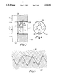
- FIG. 3 is a sectional view of a part of a wear plate immediately surrounding a nozzle member according to an exemplary embodiment
- FIG. 4 shows the nozzle member of FIG. 3, seen from the side facing away from the mold chamber
- FIG. 5 is a greatly magnified sectional view showing the engagement between the screw-threads in the arrangement of FIG. 3,
- FIGS. 6, 7, 8 and 9 show four different examples of the use of mechanical locking means for securing the proper engagement of the nozzle member, while FIG. 7a shows a portion of FIG. 7 drawn to an enlarged scale,
- FIG. 10 shows a second exemplary embodiment of a nozzle member, seen from the mold-chamber side
- FIG. 11 shows the nozzle member of FIG. 10 in an arrangement similar to that of FIG. 3, and
- FIG. 12 shows an embodiment of a nozzle member used in a comparatively thin wear plate.
- a sand supply chamber 1 of which only the lower part is shown, is adapted to receive sand from a sand supply container (not shown), and to store this mold sand 2 temporarily.
- air under pressure is supplied to the closed space above the sand 2 as indicated by arrows 3, so that the mold sand 2, which is being kept in a fluidized state by air introduced through fluidization ducts 5, may be forced through an outlet 4 downwardly into a mold chamber 8.
- the mold chamber 8, situated as shown below the sand supply chamber 1, is limited above and below by a top plate 6 and a bottom plate 7 respectively, and in the lateral directions by two pattern plates 9 and 10, as well as two side plates covering the sides of the mold chamber 8 facing toward and away from the observer, and hence not visible in FIG. 1.
- the pattern plates 9 and 10 are supported by squeeze plates 11 and 12 respectively.
- a piston arrangement, of which only a ram 11 is shown, is adapted to move the two squeeze plates 11 and 12 and hence the two pattern plates 9 and 10 towards each other with great force.
- a mold 19 in the present example adapted to be one of a number of individual mold parts to be arranged closely together to form a so-called mold string (not shown) such as described e.g. in the international application No. PCT/DK90/00079 from the present applicant.
- the air contained in the sand must necessarily escape from the mold chamber 8, and means for this purpose, that are visible in FIG. 1, comprise a number of air passages 14 formed in the pattern plates 9 and 10, gaps 15 between the top and bottom plates 6 and 7 on the one hand and the pattern plates and squeeze plates 9, 10, 11 and 12 respectively on the other hand, as well as gaps (not shown) between the latter and the side plates (not shown) referred to above.
- the air-escape facility provided by the passages and gaps referred to above is, however, not always sufficient to ensure an adequate removal of air from the mold or mold part being formed.
- This problem has been solved in previously known apparatus of this kind by means of a number of air-escape nozzles being distributed over those areas of the plates bounding the mold chamber, where a reduced flow resistance for the escaping air is desired. These nozzles are usually distributed over a number of so-called wear plates, used to line the walls bounding the mold chamber.
- the wear plate 16 of which only a small part is shown, has a number of through bores 17 with an internal screw-thread 18 extending to within a short distance of the mold-chamber surface 20 facing a mold chamber, e.g. the mold chamber 8 shown in FIGS. 1 and 2.
- a nozzle member 21 having an external screw-thread 22 is screwed into the bore 17 in engagement with the latter's internal thread 18.
- an abutment tool 23 with a plane surface 24 facing the mold-chamber surface 20 on the wear plate 16 is held with considerable force as indicated by arrows 25 in abutment with the mold-chamber surface 20, the small gap shown in FIG. 3 being reduced to zero.
- the nozzle member 21 is then screwed tightly up against the plane surface 24 on the abutment tool 23, after which the nozzle member 21 is secured in the position thus achieved in the bore 17 in a manner to be described below, before the abutment tool 23 is removed, leaving the plane mold-chamber face 26 in precise alignment with the mold-chamber surface 20 on the wear plate 16.
- the air will flow through a peripheral groove 28 and a number of holes 29, of which the latter advantageously may be used as engagement holes for a tool (not shown), with which the nozzle member 21 may be turned.
- a preferred method of securing the nozzle member 21 in the position referred to above comprises the use of a settable cement in the following manner:
- a small quantity of a settable cement is applied to the internal thread 18 in the wear plate 16 and/or the external thread 22 on the nozzle member 21, preferably by applying the cement to the internal thread 18 only, before inserting the nozzle member 21 in the bore 17, in this manner preventing the cement from coming into contact with tools or the operator's fingers.
- the nozzle member 21 is now screwed tight up against the abutment tool 23, the latter being held in engagement with the mold-chamber surface 20 for a period of time sufficient to allow the settable cement 30 shown in FIG. 5 to set and thus hold the flanks 31 on the nozzle-member thread 22 facing away from the mold-chamber surface 20 in abutment with the flanks 32 on the bore thread 18 facing toward the mold-chamber surface 20.
- the nozzle member 21 When the nozzle member 21 has been secured in the bore 17 in the manner described above, it cannot be dislodged by the pressure exerted upon it by the mold sand during the pressing operation described above with reference to FIGS. 1 and 2. Further, the nozzle member 21 will not interfere with the subsequent removal of the finished mold or mold part from the mold chamber by pushing the mold or mold part through the mold chamber in sliding relation with the wear plate 16, as the mold-chamber face 26 of the nozzle member 21 neither protrudes into the mold chamber nor recedes from it.
- nozzle member 21 If the nozzle member 21 is to be removed from the wear plate 16, this can be done simply by unscrewing it using the tool referred to above. This will, of course, cause the bond provided by the cement 30 to be broken, but will not damage the threads 18 and 22, provided that the cement 30 is of a kind having a limited shear strength.
- LOCTITE®-242 of normal strength an anaerobic adhesive
- the external screw-thread 22 on the nozzle member has been deformed slightly by a tool (not shown) acting on the ridge or peak of the thread in the direction towards the abutment tool 23 (shown in FIG. 3) forming axially directed protrusions 40.
- Protrusions 40 have an axial width greater than the axial spacing between threads 18 and 22 shown in FIG. 5 as being occupied by the settable cement 30.
- the protrusions 40 will engage and be deformed by the oppositely situated flanks 41 on the thread 18 in the wear plate, the force of reaction pressing and keeping the flanks 31 in abutment with the flanks 32 in a manner similar to that of the settable cement 30 described with reference to FIG. 5.
- the nozzle member 21a has been provided with two springy wings 42 by cutting two slits 43 in the part of the nozzle member 21a facing away from the mold-chamber face 26.
- the wings 42 Prior to insertion, the wings 42 have been deformed beyond their elastic limit into the shape indicated in dotted lines, so that when the nozzle member 21a is screwed into the bore 17 in the wear plate 16 so as to come into abutment with the the abutment tool 23--if necessary after temporarily holding the wings 42 more or less at right angles to the bore as shown--the "forward" flanks on the external thread 44 on the wings 42 will press against the "rearward" flanks on the internal thread 18 in the bore 17 as indicated in the enlarged part-sectional view shown in FIG.
- a nozzle member 21b is equipped with a threaded locking ring 33 with internal teeth 34.
- a nozzle member 21b has been placed in position by screwing the mold-chamber face 26 tight up against the surface 24 on the abutment tool 23 in the manner described with reference to FIG. 3, it is secured in position by screwing the locking ring 33 tight against the part of the nozzle member 21b carrying the external thread 22, thus locking the latter in the position shown in FIG. 5.
- Turning of the toothed locking ring 33 may be effected by means of an externally toothed mandrel (not shown), that may be inserted through the hole 29; this mandrel may, of course, also be used when turning the whole nozzle member 21b.
- the toothed looking ring 33 On the nozzle member 21b, it may be necessary to manufacture the latter in two parts, to be assembled when the locking ring 33 has been placed in position, or to reduce the diameter of the part carrying the mold-chamber face 26 to allow passage of the locking ring 33. In the latter case, the diameter of the unthreaded part of the bore 17 should, of course, be reduced correspondingly.
- the securing is achieved by means of an externally threaded locking plate 35, which is placed at a small distance from the nozzle member 21c proper, a screw 36 in a controlled manner pulling the nozzle member toward the locking plate, so that the nozzle member 21c is maintained in its final position with the mold-chamber face 26 screwed tight up against the abutment tool 23.
- the annular gap 27 shown in FIG. 3 is replaced by a number of linear slits 37 formed in the nozzle member 38 proper.
- the nozzle member 38 is inserted and secured in the operating position in the same manner as described above with reference to FIGS. 3-6, possibly using a turning tool (not shown) adapted to engage the widened parts 39 of the slits 37.
- FIG. 12 shows an embodiment of the nozzle member 21d adapted for use in a comparatively thin wear plate 16.
- the nozzle member 21d is preferably secured in position with its mold-chamber face 26 screwed tight up against the abutment tool 23 in the same manner as described with reference to FIG. 5 or FIG. 6.
- All the nozzle members 21, 21a, 21b, 21c and 21d and 38 may be manufactured from materials previously used for such nozzles, such as steel or a suitable powder-metallurgical material, preferably surface-treated and/or heat-treated for high wear resistance.
Landscapes
- Engineering & Computer Science (AREA)
- Mechanical Engineering (AREA)
- Casting Devices For Molds (AREA)
Applications Claiming Priority (2)
| Application Number | Priority Date | Filing Date | Title |
|---|---|---|---|
| DK045991A DK168694B1 (da) | 1991-03-14 | 1991-03-14 | Fremgangsmåde ved fremstilling af en slidplade me d luftafgangsdyser til brug i presser til fremstilling af kasseløse sandforme, samt luftafgangsdyse til brug ved fremgangsmådens udøvelse. |
| DK0459 | 1991-03-14 |
Publications (1)
| Publication Number | Publication Date |
|---|---|
| US5220953A true US5220953A (en) | 1993-06-22 |
Family
ID=8093793
Family Applications (1)
| Application Number | Title | Priority Date | Filing Date |
|---|---|---|---|
| US07/849,500 Expired - Fee Related US5220953A (en) | 1991-03-14 | 1992-03-11 | Near plate with air-escape nozzles for use in presses for making flaskless sand molds |
Country Status (3)
| Country | Link |
|---|---|
| US (1) | US5220953A (da) |
| DE (1) | DE4208142C2 (da) |
| DK (1) | DK168694B1 (da) |
Cited By (1)
| Publication number | Priority date | Publication date | Assignee | Title |
|---|---|---|---|---|
| US6976011B1 (en) * | 1998-06-15 | 2005-12-13 | Societe Francaise Du Radiotelephone | Process for making remote payments for the purchase of goods and/or a service through a mobile radiotelephone, and the corresponding system and mobile radiotelephone |
Citations (6)
| Publication number | Priority date | Publication date | Assignee | Title |
|---|---|---|---|---|
| US3188701A (en) * | 1962-12-18 | 1965-06-15 | Kenneth R Mcintyre | Core box vent |
| US3529656A (en) * | 1967-08-16 | 1970-09-22 | Barnett Levy | Venting members for core boxes and other moulds |
| DE3026146A1 (de) * | 1980-07-10 | 1982-02-25 | Gottfried 6335 Lahnau Zimmermann | Duese zum entlueften, belueften, bedampfen oder bespruehen von formen |
| DE3319463A1 (de) * | 1983-05-28 | 1984-11-29 | Carl Aug. Picard GmbH & Co KG, 5630 Remscheid | Auskleidungsplatte fuer den formraum an formmaschinen |
| DE3613351A1 (de) * | 1986-04-19 | 1987-10-22 | Winter Fritz Eisengiesserei | Duese zum entlueften eines formwerkzeugs, insbesondere eines giessereiwerkzeugs |
| US4716953A (en) * | 1986-05-13 | 1988-01-05 | Burnswick Industrial Supply Co. | Vent plug |
-
1991
- 1991-03-14 DK DK045991A patent/DK168694B1/da not_active IP Right Cessation
-
1992
- 1992-03-11 US US07/849,500 patent/US5220953A/en not_active Expired - Fee Related
- 1992-03-13 DE DE4208142A patent/DE4208142C2/de not_active Expired - Fee Related
Patent Citations (6)
| Publication number | Priority date | Publication date | Assignee | Title |
|---|---|---|---|---|
| US3188701A (en) * | 1962-12-18 | 1965-06-15 | Kenneth R Mcintyre | Core box vent |
| US3529656A (en) * | 1967-08-16 | 1970-09-22 | Barnett Levy | Venting members for core boxes and other moulds |
| DE3026146A1 (de) * | 1980-07-10 | 1982-02-25 | Gottfried 6335 Lahnau Zimmermann | Duese zum entlueften, belueften, bedampfen oder bespruehen von formen |
| DE3319463A1 (de) * | 1983-05-28 | 1984-11-29 | Carl Aug. Picard GmbH & Co KG, 5630 Remscheid | Auskleidungsplatte fuer den formraum an formmaschinen |
| DE3613351A1 (de) * | 1986-04-19 | 1987-10-22 | Winter Fritz Eisengiesserei | Duese zum entlueften eines formwerkzeugs, insbesondere eines giessereiwerkzeugs |
| US4716953A (en) * | 1986-05-13 | 1988-01-05 | Burnswick Industrial Supply Co. | Vent plug |
Cited By (1)
| Publication number | Priority date | Publication date | Assignee | Title |
|---|---|---|---|---|
| US6976011B1 (en) * | 1998-06-15 | 2005-12-13 | Societe Francaise Du Radiotelephone | Process for making remote payments for the purchase of goods and/or a service through a mobile radiotelephone, and the corresponding system and mobile radiotelephone |
Also Published As
| Publication number | Publication date |
|---|---|
| DK168694B1 (da) | 1994-05-24 |
| DK45991A (da) | 1992-09-16 |
| DE4208142A1 (de) | 1992-09-24 |
| DE4208142C2 (de) | 1994-04-14 |
| DK45991D0 (da) | 1991-03-14 |
Similar Documents
| Publication | Publication Date | Title |
|---|---|---|
| DE69416356T2 (de) | Vorrichtung und Verfahren zum Spritzgiessen mit örtlicher Druckbeaufschlagung | |
| DE69317205T2 (de) | Spritzgiessmaschine vom örtlichen Druckbeaufschlagungstyp | |
| DE3839536C2 (de) | Spritzgießeinrichtung für Informationsplatten und Spritzgießverfahren | |
| AT405494B (de) | Verfahren zum herstellen einer ebenen reiblamelle | |
| DE68919462T2 (de) | Verfahren und Vorrichtung zum Regeln eines Druckgiessvorganges durch Steuerung der Bewegung des Druckkolbens. | |
| DE3336173A1 (de) | Presse mit mehreren spritzkolben zur gleichzeitigen herstellung mehrerer kunststoffpressteile | |
| US5220953A (en) | Near plate with air-escape nozzles for use in presses for making flaskless sand molds | |
| DE69104244T2 (de) | Topf für Formmassen mit einem konfigurierten Boden. | |
| EP3056297B1 (de) | Verwendung eines speisereinsatzes und verfahren zum herstellen einer giessform mit vertikaler formteilung | |
| DE2644670A1 (de) | Nadelventil fuer kunststoff-spritzgiesswerkzeuge | |
| DE69709787T2 (de) | Giessereimaschinenaufbau, z.b. formmaschine und transportvorrichtung für grünsandformen | |
| DE69727685T2 (de) | Dichtender auswurfzapfen | |
| DE3319463C2 (de) | Auskleidungsplatte für den Formraum an Formmaschinen | |
| DE69303381T2 (de) | Hydraulisch betriebene Formmaschine mit Schliess und Klemmzylindern | |
| DE10135125C1 (de) | Verfahren und Vorrichtung zum Verfahren eines Spritzaggregates einer Kunststoffverarbeitungsmaschine | |
| WO1995020102A1 (de) | VERFAHREN ZUR HERSTELLUNG EINES DECKELS AUS LEICHTMETALLGUss SOWIE DECKEL AUS LEICHTMETALLGUSS | |
| DE69225893T2 (de) | Lokal druckgebende spritzgiessmaschine | |
| DE4419555C1 (de) | Stranggießer für Stranggießanlagen, insbesondere für thermoplastische Kunststoffe | |
| DE3635481C1 (en) | Nozzle head for the machine application of glue with a detachably fastened nozzle plate | |
| DE102007047136B4 (de) | Schmiedeverfahren | |
| EP0661121A1 (de) | Auskleidungsplatte für Formkammern | |
| DE2420461B2 (de) | Vorrichtung zur Sicherung der relativen Lage zweier lösbar miteinander verbundener Bauteile | |
| DE4104288A1 (de) | Vorrichtung zur biegekompensation an formwerkzeugen | |
| EP1659306B1 (de) | Reiblamelle sowie Verfahren zum Einbringen einer Nut in den Reibbelag einer Reiblamelle | |
| DE977014C (de) | Druckgiessverfahren unter Verwendung einer Kaltkammerdruckgiessmaschine |
Legal Events
| Date | Code | Title | Description |
|---|---|---|---|
| AS | Assignment |
Owner name: DANSK INDUSTRI SYNDIKAT A/S, DENMARK Free format text: ASSIGNMENT OF ASSIGNORS INTEREST.;ASSIGNOR:JACOBSEN, ARNE T.;REEL/FRAME:006058/0678 Effective date: 19920217 |
|
| FEPP | Fee payment procedure |
Free format text: PAYOR NUMBER ASSIGNED (ORIGINAL EVENT CODE: ASPN); ENTITY STATUS OF PATENT OWNER: LARGE ENTITY |
|
| FEPP | Fee payment procedure |
Free format text: PAYER NUMBER DE-ASSIGNED (ORIGINAL EVENT CODE: RMPN); ENTITY STATUS OF PATENT OWNER: LARGE ENTITY Free format text: PAYOR NUMBER ASSIGNED (ORIGINAL EVENT CODE: ASPN); ENTITY STATUS OF PATENT OWNER: LARGE ENTITY |
|
| FPAY | Fee payment |
Year of fee payment: 4 |
|
| FPAY | Fee payment |
Year of fee payment: 8 |
|
| REMI | Maintenance fee reminder mailed | ||
| LAPS | Lapse for failure to pay maintenance fees | ||
| LAPS | Lapse for failure to pay maintenance fees |
Free format text: PATENT EXPIRED FOR FAILURE TO PAY MAINTENANCE FEES (ORIGINAL EVENT CODE: EXP.); ENTITY STATUS OF PATENT OWNER: LARGE ENTITY |
|
| STCH | Information on status: patent discontinuation |
Free format text: PATENT EXPIRED DUE TO NONPAYMENT OF MAINTENANCE FEES UNDER 37 CFR 1.362 |
|
| FP | Lapsed due to failure to pay maintenance fee |
Effective date: 20050622 |