US521996A - Valve for air-brakes - Google Patents
Valve for air-brakes Download PDFInfo
- Publication number
- US521996A US521996A US521996DA US521996A US 521996 A US521996 A US 521996A US 521996D A US521996D A US 521996DA US 521996 A US521996 A US 521996A
- Authority
- US
- United States
- Prior art keywords
- pressure
- valve
- air
- pipe
- piston
- Prior art date
- Legal status (The legal status is an assumption and is not a legal conclusion. Google has not performed a legal analysis and makes no representation as to the accuracy of the status listed.)
- Expired - Lifetime
Links
- 230000001105 regulatory effect Effects 0.000 description 7
- 230000001276 controlling effect Effects 0.000 description 2
- 238000012856 packing Methods 0.000 description 2
- 241000209527 Arum Species 0.000 description 1
- 235000006481 Colocasia esculenta Nutrition 0.000 description 1
- RUPBZQFQVRMKDG-UHFFFAOYSA-M Didecyldimethylammonium chloride Chemical compound [Cl-].CCCCCCCCCC[N+](C)(C)CCCCCCCCCC RUPBZQFQVRMKDG-UHFFFAOYSA-M 0.000 description 1
- 101100379079 Emericella variicolor andA gene Proteins 0.000 description 1
- 241000404883 Pisa Species 0.000 description 1
- 238000012550 audit Methods 0.000 description 1
- 238000007664 blowing Methods 0.000 description 1
- 238000010276 construction Methods 0.000 description 1
- 238000010586 diagram Methods 0.000 description 1
- 239000000428 dust Substances 0.000 description 1
- 210000004907 gland Anatomy 0.000 description 1
- 238000007689 inspection Methods 0.000 description 1
- 239000000463 material Substances 0.000 description 1
- 230000000717 retained effect Effects 0.000 description 1
Images
Classifications
-
- B—PERFORMING OPERATIONS; TRANSPORTING
- B60—VEHICLES IN GENERAL
- B60T—VEHICLE BRAKE CONTROL SYSTEMS OR PARTS THEREOF; BRAKE CONTROL SYSTEMS OR PARTS THEREOF, IN GENERAL; ARRANGEMENT OF BRAKING ELEMENTS ON VEHICLES IN GENERAL; PORTABLE DEVICES FOR PREVENTING UNWANTED MOVEMENT OF VEHICLES; VEHICLE MODIFICATIONS TO FACILITATE COOLING OF BRAKES
- B60T15/00—Construction arrangement, or operation of valves incorporated in power brake systems and not covered by groups B60T11/00 or B60T13/00
- B60T15/02—Application and release valves
- B60T15/04—Driver's valves
- B60T15/048—Controlling pressure brakes of railway vehicles
Definitions
- the present invention is made with refer-Y ence to admitting air under pressure into the train pipe when the pressure in the train pipe is less than the pressure desired, so as to maintain in such train pipe whatever pressure is necessary for operating upon the brake mechanism, or to relieve the pressure to any desired extent.
- a piston is con! nected within a cylinder and the pressure from the train pipe is admitted to one side of this piston and a pressure from a small storage reservoir is admitted to the other side of this piston, and the valve is moved either one Way or the other according towhichpressure predominatesf
- The'valve which the engineer manipulates admits air 'under pressure into the small storage reservoir, and to this small storage reservoir a gage-is applied, so that the engineer can, by inspection, ascertainthe pressure in the small storage reservoir, and in consequence of the regulating valve aforesaid the pressure in the trainpipe is made to correspond or nearly so to the pressure in the small storage reservoir; and I make use ot ⁇ an exhaust valve to which a piston isconnected in a cylinder, and one side of the piston is open to the pressure in the train pipe and the other side of the piston is open to lthe pressure in the small storage reservoir, so that when the pressure in the train pipe exceeds the pressure in the small storage reservoir, the escape valve is opened to allow the air to pass
- Figure l is a vertical sec tion of the improved valve mechanism.
- Fig. 2 is a plan of the same.
- Fig. 3 is a cross section at the line 0o, oo.
- Figs. 4 and 5 'are diagrammatic sections of the engneers cock
- Fig. 6 is an inverted plan of the valve in the exhaust pipe.
- the ⁇ emgineerls valve K is ina pipe L leadinlg from the main reservoir pipe A to the passageor pipe 11,1and from this pipell the pipe 17 leads to ⁇ the small reservoirM, ⁇ and a pressure gage ⁇ is to be applied at ⁇ N upon the pipel', and there -should be another press-t ure gageO upon the pipe A from the main reservoir.
- the pistons -20 and 21 are to move air-tight orsubstantiallyso yin the pressure regulator cylinder P, and there isa groove 217 near the edtranee tothepipe 18 and the air pressure from the pipe A between the pistons ⁇ 20 and 2l is balanced; and theiairpressure between theeap 28 andthe piston 20 is equal to the pressure between thepistons 20and2l whenever thcpiston 20 is adjacent tothegroove 27, and the fair pressure upon the ⁇ piston 2l is resistedbyth'e spring 22, and Whenever the pressure in lthe pipe 18. ⁇ and on the ⁇ top of the piston ⁇ 2O. is less than the pressure on the under ⁇ side of'said piston 20. the 'spring kmoves the parts and causes the piston 20. toadmit air to said pipe 18. and by this means the maximum pressure of air in 'the pipe 18. will be regulated by the adjustment of the spring 22.
- the engineers cock K is three-way, as illustrated in the diagram Figs. 4: and 5, so that when turned into the position represented in Fig. 4t the air pressure will pass by 18, L, 11
- theengineer turns his valve, allowing ⁇ pressure ⁇ to escape from the small storage "reservoirso ⁇ las toureduce the pressure -above the pistoni-Land the train pipe pressure lifts the valvel, allowing lthe 'air to discharge lfrom the train pipe moreor lessra'pidly.
- the handle of the engineers valve may be provided With a segment or dial as indicated in Fig. ⁇ 2 and that When the handle and plug are in the position indicated in Fig. 5, the mark on the dial or segment should be that ordinarily applied in air brakes, namely On lap, and the mark Emergency stop should correspond to the handle When the passage Ways are entirely open to the air pipe 29, and themark Service stop should be intermediate between the On lap and the Emergency stop,7 and when the plug is in the position indicated in Fig. 4, the handle should correspond to the Full release mark on the dial.
- the capacity of the engineers valve is increased, because,in addition to the duties heretofore performed bythe ordinary engineers brake and equalizing discharge valve, the engineer is enabled to control the pressure in the train pipe by simply turning the handle until the pressure in the gage N indicates the pressure desired for the train pipe, and the operations of the parts thereafter are automatic, saving and excepting the risk of 'leakage which may lessen the pressure in the small storage reservoir, but
- the engineers valve is the only device of this apparatus that is necessarily placed Within the cab, and the air valves can be located in any desired position Which is advantageous,because the parts need not be exposed to the heat of the boiler, and besides this the air blowing out from the exhaust valveneed not come into the cab and the risk of dust being blown into the engineers eyes ⁇ is lessened, and the 'durability and reliability of the parts are increased by being able to locate the valves where they are not exposed toheat;
- an air brake apparatus the combination with the train pipe andthe pipe that sup plies air under pressure, of an intermediate valve body having a seat between the air supply and the train pipe, a removable cylinder bolted to the body of the Valve, an air supply Valve audits piston Within the cylinder, ports j for supplying air at opposite sides of the pisg ton to open and close the valve, an air discharge valve, a piston for moving the same, i and a cylinder for the piston connected to ⁇ the body of the valve, there being ports for ⁇ the admission of air to act upon the piston and regulate the discharge valve, substang tially as set forth.
Landscapes
- Engineering & Computer Science (AREA)
- Transportation (AREA)
- Mechanical Engineering (AREA)
- Valves And Accessory Devices For Braking Systems (AREA)
Description
' (Nd-Model.)
J. P. vooRHBBs. VALVE FOR AIR BRAKES.
No. 521,996. i -Patented June 26,
m: rennen. Lxrriosmf'wms com-muv.
wAsmNa'roN. n. c.
, cylinders, and with the engineers brake andA UNITE STATES Arum* turion@ VALVE FO R `Al R-B RAKES.
SPECIFICATION forming part of Letters Patent No. 521,996, dated June 26, 1894.
Application led August 23, 1893. Serial No. 483.818. (No model.)
To a/ZZ whom, it may concern:
Be it known that I, JEREMIAH F. VOOR- HEES, a citizen of the United States, residing at West Philadelphia, in the county of Philadelphia and State of Pennsylvania, have invented an Improvement in Valves for Air- Brakes, of which the following is a specication.
In air brakes for railway trains it has been usual to provide on the engine a pump for compressingl air into a main reservoir, and the engineers valve is appliedin a pipe that passes from the main reservoir tothe train pipe, and by moving this Valve the engineer admits airto pass from the main reservoir along the train pipe so as to store the air in the auxiliary reservoirs beneath the respective cars, and from these auxiliary reservoirs the air is allowed to act in the brake cylinder and apply the brakes when the pressure in the train pipe is lessened. I
In some characters of air brake apparatus it is important to lessen the pressure of air in the train pipe to a predetermined pressure and to hold or maintain that pressure throughout the train apparatus, even though there may be leaks in the train pipe or thebrake equalizing discharge valve' heretofore made use of, difliculty has been experienced in controlling the pressure of the air in the train pipe reliably.
The present invention'is made with refer-Y ence to admitting air under pressure into the train pipe when the pressure in the train pipe is less than the pressure desired, so as to maintain in such train pipe whatever pressure is necessary for operating upon the brake mechanism, or to relieve the pressure to any desired extent.
With this object in View I make use of a regulating Valve applied at a valve seat between the main reservoir and the train pipe,
and to this regulating valve a piston is con! nected within a cylinder and the pressure from the train pipe is admitted to one side of this piston and a pressure from a small storage reservoir is admitted to the other side of this piston, and the valve is moved either one Way or the other according towhichpressure predominatesf The'valve which the engineer manipulates admits air 'under pressure into the small storage reservoir, and to this small storage reservoir a gage-is applied, so that the engineer can, by inspection, ascertainthe pressure in the small storage reservoir, and in consequence of the regulating valve aforesaid the pressure in the trainpipe is made to correspond or nearly so to the pressure in the small storage reservoir; and I make use ot` an exhaust valve to which a piston isconnected in a cylinder, and one side of the piston is open to the pressure in the train pipe and the other side of the piston is open to lthe pressure in the small storage reservoir, so that when the pressure in the train pipe exceeds the pressure in the small storage reservoir, the escape valve is opened to allow the air to pass out of the train pipe until the pressures are equalized, thus placing the air pressure in the train pipe entirely under the control of the engineer; and-I employ an automatic regulating valve between the main reservoir'and the engineers valve so as to prevent the pressure employed in the brake mechanism from becoming too high under any circumstances.
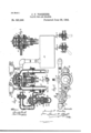
In the drawings, Figure l is a vertical sec tion of the improved valve mechanism. Fig. 2 is a plan of the same. "Fig. 3 is a cross section at the line 0o, oo. Figs. 4 and 5 'are diagrammatic sections of the engneers cock, and Fig. 6 is an inverted plan of the valve in the exhaust pipe.
reservoir upon the engine into which the air is pumped in the usual manner, and B is the 'connection to the train pipethat extends bolted, the parts being made air-tight by suitable packing material, and this cylinder E has a removable head 6, and within the cylinder E is a piston F withV a stem 7 forming a valve that closes upon the seat 4, and the stem of this valve 7 passes through a packing gland 8, and there is a port 9 leading from IOC) in a movable seat 12 which also forms a main` when the piston H is moved downwardly, the 1 valve Icloses the `passage ways 13; when such i piston I-l `and valve I are slightly lifted the Valve I lopen-s the passage ways `13,`and when the piston I-I `is lifted still farther the nuts 14 lift -Tthefmain `air valve 12 off its seat, allow-` ing the free and 'rapid escape of air through the exhaust 'pipe C, the passage way or port 15 `leading' from the train pipe B into the cylinder G below the piston H; and there is aport 16 leading from the pipe 11 into `the cylinder G above the piston H.
The `emgineerls valve K is ina pipe L leadinlg from the main reservoir pipe A to the passageor pipe 11,1and from this pipell the pipe 17 leads to `the small reservoirM, `and a pressure gage `is to be applied at `N upon the pipel', and there -should be another press-t ure gageO upon the pipe A from the main reservoir.
The pipe 18 totheengineers valve K `might lea'd "direct from the `pipe A or main reservoir; I however prefer to employ #a pressure regulator P between `thefpipe l-S and the kpipe 19 that connects to the pipe A. This pressure regulator is in the form ofacylindfer hav` ing with-in it `two pistons 2O and 21 connected together by -a stem `and `moved in one direction by a spring 22 which can be adjusted for more `or less pressure by fa screw sleeve `23 passingthrough the head 2lof the pressure regulator cylinder P, and the removable cap 25 isscrewed upon the head 24 to prevent access =t`o the screw sleeve 23 until the said kcap 25 has been reniovedgand it isiadv'an-tageous to femploya lock nut 26 to prevent the-screw sleeve 23 becoming looseor the adjustment varied iby ithejarand vibration of theiengine.
The pistons -20 and 21 are to move air-tight orsubstantiallyso yin the pressure regulator cylinder P, and there isa groove 217 near the edtranee tothepipe 18 and the air pressure from the pipe A between the pistons`20 and 2l is balanced; and theiairpressure between theeap 28 andthe piston 20 is equal to the pressure between thepistons 20and2l whenever thcpiston 20 is adjacent tothegroove 27, and the fair pressure upon the `piston 2l is resistedbyth'e spring 22, and Whenever the pressure in lthe pipe 18. `and on the `top of the piston `2O. is less than the pressure on the under `side of'said piston 20. the 'spring kmoves the parts and causes the piston 20. toadmit air to said pipe 18. and by this means the maximum pressure of air in 'the pipe 18. will be regulated by the adjustment of the spring 22.
The engineers cock K is three-way, as illustrated in the diagram Figs. 4: and 5, so that when turned into the position represented in Fig. 4t the air pressure will pass by 18, L, 11
vand 17 into the storage reservoir M, and the pressure in such storage reservoir M will be the maximum pressure to which the pressure regulator P may be set. Whenf `the plug is turned into 'the position indicated in Fig. 5, the pressure will be maintained in the small storage reservoir M as the ports of the engineers valve are all closed,and by turning the valve around the `air `may be @allowed to escape from the small "storage reservoir ito the atmosphere by the port "29.
It is now toybe understood that underierdinary *circumstances the `engineer turilr's the valve K and admits air into the sm all storage reservoir M until the gage N indicates lthe pressure desired in the train pipepand this pressure will be substantially maintainedbecause if the pressure in the train pipe "becomes less than the pressure in the storage reservoir M the pressure from SM acting through 11 Pand l0 lifts the piston l and valve 7, allowing pressure fromltheinainreservoir to pass by the pipe A randvalve fse'a't 4t into the trai'n'ipipe, and as `fsoonas thefpres'sure in the train pipe 'equals that iin the isterage reservoirthevalve 7 again @closes cnilts c seat; and the supplyof `ai-r will be in llproportion to the demand for the :same in theitrain pipeat all times, `and should there be leakage the same will be made up iso as to imaintain lthe pressure; and lon the other hand, lit' the pressure in the train pipe increases fbeyondthepressu rein the storage reservoir from any Lcause, the train :pipe pressure `:acting be low the pistonI-I williraise the piston land lthe valve I, vallowing the train pipe pressure to escape until itlequalizesthe pressurieupou the top ofthe piston II.
If the brakes are to be applied-,theengineer turns his valve, allowing `pressure `to escape from the small storage "reservoirso `las toureduce the pressure -above the pistoni-Land the train pipe pressure lifts the valvel, allowing lthe 'air to discharge lfrom the train pipe moreor lessra'pidly. For an'eure'rgency stop the-plu g of the `engineers valve is turned to fully open the escape to the atmosphere from `th-e storage reservoir through the port and pipe `29, rand the sudden relief =o`f ithe pressure causes the train `pi-pe pressure itolliift the piston H, valve I fan-d falso the main fair valve 12, so as tofgive free andrapididischarge for `theair from the trainpipe. :In this manner the brakes will be applied rapidly foran emergeucystop,"and for controllin'gthe brakes Whiletheitrain maybe running on :a `down grade,=or for relieving the brakes ,f .1;radually whencoming to astop, theengineerlcanfrnaintain in the train pipe any desired pressure,
IOC
IIO
and that pressure will be indicated by theY gage N regardless of the pressure indicated by the gage O.
It will be observed that the apparatus might be regulated by theengineers valve Without the useof a small storage reservoir, but it is advantageous to employ this small storage reservoir in order that there may be a sufficient reserve of air under pressure retained in that reservoir for actingin connection with the valves without requiring such constant and careful attention vas Would be necessary on the part of the engineer if the said storage reservoir were dispensed with. It will also be apparent that the pressure regulator Pmight be dispensed with and that the special advantage in using the said pressure regulator is to determine the maximum pressure that can be used in the train pipe, because the pressure in the small storage reservoir can never exceed the pressure which the regulator P is set to admit, and hence the pressure in the train pipe is regulated thereby through the intervention of the pistons that are controlled by the .pressure in the storage reservoir, and the pressure regulator P prevents the engineer applying too much pressure in the train pipe through carelessness or inattention, and this is convenient because a more nearly uniform pressure can be maintained in the brake apparatus of different trains by providing such pressure regulator upon all the engines, thus removing a difficulty that is sometimes found in throwing off all the brakes upon the train Where a train may be made up of one or more cars upon which the brake may have been applied by a greater pressure from the engine from which such car has been disconnected than is employed in the engine of the train to which such car is connected.
It is to be understood that the handle of the engineers valve may be provided With a segment or dial as indicated in Fig. `2 and that When the handle and plug are in the position indicated in Fig. 5, the mark on the dial or segment should be that ordinarily applied in air brakes, namely On lap, and the mark Emergency stop should correspond to the handle When the passage Ways are entirely open to the air pipe 29, and themark Service stop should be intermediate between the On lap and the Emergency stop,7 and when the plug is in the position indicated in Fig. 4, the handle should correspond to the Full release mark on the dial. By the present improvements the capacity of the engineers valve is increased, because,in addition to the duties heretofore performed bythe ordinary engineers brake and equalizing discharge valve, the engineer is enabled to control the pressure in the train pipe by simply turning the handle until the pressure in the gage N indicates the pressure desired for the train pipe, and the operations of the parts thereafter are automatic, saving and excepting the risk of 'leakage which may lessen the pressure in the small storage reservoir, but
this can be instantly restored by the engineer turning the handle of lhis valve for that purpose. l I
The engineers valve is the only device of this apparatus that is necessarily placed Within the cab, and the air valves can be located in any desired position Which is advantageous,because the parts need not be exposed to the heat of the boiler, and besides this the air blowing out from the exhaust valveneed not come into the cab and the risk of dust being blown into the engineers eyes `is lessened, and the 'durability and reliability of the parts are increased by being able to locate the valves where they are not exposed toheat;
and lby my improvements I avoid thev use of springs and'levers for acting upon the valves and control such valves entirely yby the air pressure, and the three-Way cock or valve that is acted upon by the engineer is of simple construction and not liable to become clogged IOC the main air discharge valve and has through it air passage ways that are opened and closed by the smaller air discharge valve, therey being a passage Way or port for admitting air under pressure from the train pipetolift the air discharge valve, and means for controlling an air pressure acting upon the piston to close such air discharge Valve, substantially as set forth.
2. The combination in an air brake apparatus with the pipe for supplying air under pressure, and the train pipe, of a valve to advmit air to the train pipe, a cylinder and piston connected with the valve for moving the same, a port for admitting air at one side of the piston from the train pipe, a storage reservoir and a connection from the same for admitting air to the other side of the piston, a valve for admitting air under pressure to the storage reservoir, and a gage for indicating the pressure, whereby the pressure in the train pipe Will correspond substantially to that indicated by the gage, substantially as set forth.
3. The combination in an air brake apparatus, of a pipe for supplying air under pressure from a reservoir, a smallr storage reservoir, a pipe from the main supply pipe anda pressure regulator for limiting the pressure of air admitted to the storage reservoir, a valve under the control of the engineer for IIO i ton to open and close the valve, substantially x valve and its piston within the cylinder, ports p for supplying air at opposite sides of the pisas set forth.
5. In an air brake apparatus the combination with the train pipe andthe pipe that sup plies air under pressure, of an intermediate valve body having a seat between the air supply and the train pipe, a removable cylinder bolted to the body of the Valve, an air supply Valve audits piston Within the cylinder, ports j for supplying air at opposite sides of the pisg ton to open and close the valve, an air discharge valve, a piston for moving the same, i and a cylinder for the piston connected to `the body of the valve, there being ports for `the admission of air to act upon the piston and regulate the discharge valve, substang tially as set forth.
Signed by me this 19th day of August, 1893.
J' ERE'MIAI-I F. VOORI'IEES.
Vitnesses:
FRANCIS C. W. ROVER, WM. F. BOYD.
Publications (1)
| Publication Number | Publication Date |
|---|---|
| US521996A true US521996A (en) | 1894-06-26 |
Family
ID=2590793
Family Applications (1)
| Application Number | Title | Priority Date | Filing Date |
|---|---|---|---|
| US521996D Expired - Lifetime US521996A (en) | Valve for air-brakes |
Country Status (1)
| Country | Link |
|---|---|
| US (1) | US521996A (en) |
-
0
- US US521996D patent/US521996A/en not_active Expired - Lifetime
Similar Documents
| Publication | Publication Date | Title |
|---|---|---|
| US521996A (en) | Valve for air-brakes | |
| US1438317A (en) | Automotive brake equipment | |
| US1230949A (en) | Variable-load brake. | |
| US1431477A (en) | Combined car-door control and air-brake equipment | |
| US563612A (en) | William k | |
| US462966A (en) | Automatic governor for air-brakes | |
| US1314975A (en) | Air brake system | |
| US1052342A (en) | Triple valve. | |
| US523937A (en) | Engineer s brake-valve | |
| US1215895A (en) | Combined automatic and straight-air valve mechanism. | |
| US1447706A (en) | Automatic retaining and release valve for air brakes | |
| US1138193A (en) | Air-brake system. | |
| US1081325A (en) | Fluid-pressure brake. | |
| US266684A (en) | Automatic air brake for railway cars | |
| US916669A (en) | Retaining-valve for automatic air-brakes. | |
| US1306504A (en) | Automatic brake | |
| US1294981A (en) | Pneumatic signal system. | |
| US1192482A (en) | Air-brake system. | |
| US2137228A (en) | Train brake equipment | |
| US1310951A (en) | Pressure brake system | |
| US1075389A (en) | Empty and load brake. | |
| US728485A (en) | Fluid-brake mechanism. | |
| US515617A (en) | Air-brake system | |
| US1042083A (en) | Straight-air brake attachment for automatic systems. | |
| US879700A (en) | Graduated-release valve. |