US521178A - Gear wheels - Google Patents
Gear wheels Download PDFInfo
- Publication number
- US521178A US521178A US521178DA US521178A US 521178 A US521178 A US 521178A US 521178D A US521178D A US 521178DA US 521178 A US521178 A US 521178A
- Authority
- US
- United States
- Prior art keywords
- die
- punch
- teeth
- billet
- gear
- Prior art date
- Legal status (The legal status is an assumption and is not a legal conclusion. Google has not performed a legal analysis and makes no representation as to the accuracy of the status listed.)
- Expired - Lifetime
Links
- 239000002184 metal Substances 0.000 description 14
- 229910052751 metal Inorganic materials 0.000 description 14
- 238000000034 method Methods 0.000 description 13
- 239000000725 suspension Substances 0.000 description 6
- 238000001816 cooling Methods 0.000 description 5
- 238000004519 manufacturing process Methods 0.000 description 5
- 229910000831 Steel Inorganic materials 0.000 description 4
- 239000010959 steel Substances 0.000 description 4
- 238000003825 pressing Methods 0.000 description 3
- 229910001018 Cast iron Inorganic materials 0.000 description 2
- CWYNVVGOOAEACU-UHFFFAOYSA-N Fe2+ Chemical compound [Fe+2] CWYNVVGOOAEACU-UHFFFAOYSA-N 0.000 description 2
- 229910000754 Wrought iron Inorganic materials 0.000 description 2
- 229910001208 Crucible steel Inorganic materials 0.000 description 1
- 229910000760 Hardened steel Inorganic materials 0.000 description 1
- 208000027418 Wounds and injury Diseases 0.000 description 1
- 230000015572 biosynthetic process Effects 0.000 description 1
- 230000009172 bursting Effects 0.000 description 1
- GPUADMRJQVPIAS-QCVDVZFFSA-M cerivastatin sodium Chemical compound [Na+].COCC1=C(C(C)C)N=C(C(C)C)C(\C=C\[C@@H](O)C[C@@H](O)CC([O-])=O)=C1C1=CC=C(F)C=C1 GPUADMRJQVPIAS-QCVDVZFFSA-M 0.000 description 1
- 238000010276 construction Methods 0.000 description 1
- 238000005520 cutting process Methods 0.000 description 1
- 230000006378 damage Effects 0.000 description 1
- 230000007547 defect Effects 0.000 description 1
- 230000000694 effects Effects 0.000 description 1
- 210000003746 feather Anatomy 0.000 description 1
- 238000005242 forging Methods 0.000 description 1
- 230000005484 gravity Effects 0.000 description 1
- 208000014674 injury Diseases 0.000 description 1
- 235000020004 porter Nutrition 0.000 description 1
- 238000009877 rendering Methods 0.000 description 1
- 230000002441 reversible effect Effects 0.000 description 1
Images

Classifications
-
- B—PERFORMING OPERATIONS; TRANSPORTING
- B21—MECHANICAL METAL-WORKING WITHOUT ESSENTIALLY REMOVING MATERIAL; PUNCHING METAL
- B21D—WORKING OR PROCESSING OF SHEET METAL OR METAL TUBES, RODS OR PROFILES WITHOUT ESSENTIALLY REMOVING MATERIAL; PUNCHING METAL
- B21D7/00—Bending rods, profiles, or tubes
- B21D7/16—Auxiliary equipment, e.g. for heating or cooling of bends
-
- Y—GENERAL TAGGING OF NEW TECHNOLOGICAL DEVELOPMENTS; GENERAL TAGGING OF CROSS-SECTIONAL TECHNOLOGIES SPANNING OVER SEVERAL SECTIONS OF THE IPC; TECHNICAL SUBJECTS COVERED BY FORMER USPC CROSS-REFERENCE ART COLLECTIONS [XRACs] AND DIGESTS
- Y10—TECHNICAL SUBJECTS COVERED BY FORMER USPC
- Y10T—TECHNICAL SUBJECTS COVERED BY FORMER US CLASSIFICATION
- Y10T29/00—Metal working
- Y10T29/49—Method of mechanical manufacture
- Y10T29/49462—Gear making
- Y10T29/49467—Gear shaping
Definitions
- Thisinvention relates to the manufacture of gear Wheels or pinions of steel or wrought iron by placing a heated billet of metal in a female die and subjecting it to hydraulic or other heavy pressure sufficient to cause the billet to flow and expand into and fill the teeth formed within the die, thereby forming a compressed gear or pinion having its teeth ready finished and of great strength and toughness. Gears of this character are described and claimed in the patent of E. W. Bliss, No. 472,664, dated April 12., 1892.
- the present invention provides an improved process or method for forming such compressed gears, and includes also an im-,
- I provide a female die formed with internal gear teeth conforming to the external teeth to be formed on the gear or pinion in every respect, except that they are made enough larger to allow for the shrinkage of the metal of the gear in cooling, and of a sufficiently greater height than the thickness of the gear or pinion to be made.
- I provide a male die or punch adapted to enter this female die, and having external teeth adapted to enter and slide into the teeth of the die.
- a billet of steel or wrought iron is formed of as large a diame-v ter as will easily enter the die, and of a height sufficient to afford the requisite metal, and this billet being first heated and then slightly cooled at one end, is inserted in the die.
- the punch or male die isthen placed against its cooler end.
- Hydraulic pressure is then applied to force the punch into the die, the latter being suitably supported on the bed of the press, and the billet is pressed down under the extremely heavy pressure and forced to flow or expand outwardly, so that its metal enters and fills the internal grooves or teeth-of the die.
- the billet is then forced out of the die either by pressure applied in the same direction, or preferablyby applying pressure in the opposite direction.
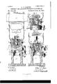
- Figure l of the accompanying drawings 18 a front elevation partly in section of a hydraulicpress to which has been applied my improved apparatus for the manufacture of gear wheels or pinions.
- Fig. 1 sa fragmentary elevation thereof partly in vertical sec tion.
- Fig. 3 is a plan of the femaledie.
- Fig. 4 is a vertical mid-section of my improved apparatus on a larger scale.
- Figs. 5 and 6 are portions of Fig. 4 showing the parts in difier- 'ent positions during different stages of the operation.
- Figs. 7 and 8 are elevations of the auxiliary punch and the lower punch respectively.
- Fig. 9 is an elevation of the gear or pinion produced by my process as it comes from the dies.
- FIG. 1 Let A designate the bed of a hydraulic press, of which B is thecylinder, 0 the ram, D the guiding cross-head, and E the head piece. These are or may be all of the usual or any suitable construction, except that the head piece E is preferably made with a hardened steel plate e inserted in it.
- a stand F which has an inner bore f and an opening f both large enough to afford ample room for the pressed gear to pass out through them.
- the top of the stand F is preferably formed of a steel disk or bed F having a hole through it'sufficiently large to permit the passage of the finished gear.
- This bed plate is constructed in any suitable manner, so that it may be readily removed or thrown out of the way, preferably by forming it with a lug and hinging it to a pintle g supported in an upright lug g formed on the stand F, as shown. To swing the plate around on this pintle, it is formed with an arm or lever G.
- the female die H is constructed to rest either on the table G, or when this is swung out of the way, on the disk F.
- The-die is constructed alike at opposite ends and is re versible. To facilitate its reversal, it is hung upon pivot pins h h on a diametrical axis intersecting its center of gravity. To enable it to be lifted and lowered with facility, it is hung by means of these pivot pins from the cross-head D, through the medium of suspension rods D D which pass freely through this cross-head, so that the head in descending after lowering the die into place, may cogtinue its descent by sliding against the r0 s.
- the internal surface of the die H is made of chilled cast iron in order to afford such extreme hardness as will resist the cutting or tearing tendency of the billet during the formation of the pressed gear and its expul sion out of the die.
- this inner chilled portion lettered 1 1s surrounded by a thick cast steel ring H which is shrunk upon it.
- the inner face of the die is formed with internal gear teeth conforming exactly to the exterior teeth upon the gear or pinion to be made, excepting only that they are sufficiently larger to allow for the shrinkage of the compressed gear in cooling.
- the height of the die is also considerably greater than thickness or width of face of the gear or pinion to be made.
- the male die or punch J is constructed to enter the female die, being formed with external gear teeth conforming to the internal teeth of the die, and adapted to slide into the die with a free or loose working fit.
- a lower punch or bottom piece K having teeth like the upper punch J, but made preferably as a shallow disk, either flat topped orwith a slight coning, as shown.
- the stand F has on its top a projection a engaging a depression a in the bottom of the disk F.
- the swinging table G has on its top a projection b, which is engaged by a depression b in either one end or the other of the female die.
- auxiliary punch L To center the auxiliary punch L relatively to either the lower punch or bottom piece K or the upper punch J, it is provided with a projection d which is adapted to enter a depression d in the bottom of the punch K, or a like depression 61 in the upper punch J.
- the billet M (Fig. 4) is made cylindrical and slightly smaller than the internal diameter of the female die within its gear teeth.
- the length of the billet is suiiicient to afford the requisite metal for making the required gear or pinion, and will vary according to the thickness or width of face desired in the gear.
- the billet is heated to a red heat, its upper end is slightly cooled, and the billet is then dropped into the die, the bottom piece or lower punch K having been first placed therein.
- the upper punchJ is then inserted in the die so that it rests on the top of the billet.
- the press is then operated, bringing the head piece E down on top of the punch J,and forcing it down into the die, thereby squeezing out the metal of the billet and causing it to expand and fiow into the teeth of the die.
- the pressure must be exceedingly heavy, for which purpose a hydraulic press is required.
- the metal of the billet consequently takes an exact impress of the interior of the die, and as the teeth thereof are smooth, the teeth formed on the billet or gear are made smooth so as to require no after finishing.
- Fig. 5 shows the dies at the end of this forcing operation.
- the press is then run up so that its cross-head D, acting through the suspension rods D, lifts the die 11, whereupon the table G is swung out of the way, and the die If is then swung over or inverted, whereupon the press is run down, thereby lowering the die ll onto the disk F. as shown in Fig. 6.
- punch L is then placed on the bottom piece or punch K, being centered therewith as shown.
- the head of the press is then again lowered, and striking the auxiliary punch L, communicates pressure through it and the bottom piece K to the pressed billet or gear M, thereby forcing it down through the female die and out through the hole in the disk F, dropping it into the cavityf' of the stand F.
- the punch J is at the same time forced out in advance of the billet.
- the punch and billet or molded gear are taken out through the opening f by tongs, the gear then appearing as in Fig. 0, that is to say, its teeth are slightly rounded at m, being the end against the bottom piece or punch K.
- the cooling of the upper end of the billet before commencing the forging operation is practically a very important step in the process.
- This cooling is for the purpose of rendering this end of the billet more resistant than its remaining portion, in order that it may sustain the strain communicated through it to the lower portion of the billet, it being understood that by reason of the resistance of the heated metal to pressure, the downward pressure per square inch is greater toward the upper end of the billet than it is toward its lower end, the tendency of which is to expand the billet to fill the die at the upper end in advance of its expansion into the die at its lower portion.
- Another serious difficulty is overcome by this means, namely, that with a billet heated uniformly throughout, the metal at the upper end of the billet is apt to flow under the pressure, not only The auxiliary punch J and of the femaledie.
- the pressed billet or gear M may be forced out of the die without inverting the die.
- the die is lowered without inverting until it rests on the disk F, and the auxillary punch L is then placed on the punch J and the head piece brought down to force the punch through the die.
- the die may still be used by forcing the billet down through. it without inverting it, accordmg to the method last described.
- a die for the manufacture of compressed wrought gears having its inner portion formed of chilled cast iron with internal gear teeth, and an outer portion consisting of a steel ring shrunk upon said inner portion to reinforce it.
- stand F removable table G
- female lie H, male (lie J, movable cross-head D, and suspension rods 1) by which 14.
- the combination of stand F, table G, female die H, male die or punch J, and anxthe lie can be lifted ofi? the table G, the latiliary punch L for forcing the compressed ter then moved out of the way, and the die 5 lowered upon the stand.
- stand F having top disk F with centering projection c
- removable table G having centering projection 12
- female die II having centering recesses 11 IO adapted to fit either of said projections Z) or c
Landscapes
- Engineering & Computer Science (AREA)
- Mechanical Engineering (AREA)
- Forging (AREA)
Description
' (No Model.) 2 sheets she'et 1.
A.T. PORTER.
PROCESS OF AND APPARATUS FOR MAKING GEAR WHEELS. No. 521,178. Patented June 12, 1894.
INVENTOR:
By his Atzomeys,
' UNITED STATES PATENT OFFICE.
ARTHUR T. PORTER, OF BROOKLYN, NEW YORK, ASSIGNOR TO THE UNITED STATES PROJEOTILE COMPANY, OF SAME PLACE.
PROCESS OF AND APPARATUS FOR MAKING GEAR-WHEELS.
SPECIFICATION forming part of Letters Patent No. 521,178, dated June l2, 1894. Application filed September 23, 1893. SerlalNo. 486,287. (No model.)
To 00% whom it may concern.-
Be it known that I, ARTHUR T. PORTER, a citizen of the United States, residing in Brooklyn, in the county of Kings and State of New York, have invented certain new and useful Improvements in Processes of and Apparatus for Making Gear-Wheels, of which the following is a specification.
Thisinvention relates to the manufacture of gear Wheels or pinions of steel or wrought iron by placing a heated billet of metal in a female die and subjecting it to hydraulic or other heavy pressure sufficient to cause the billet to flow and expand into and fill the teeth formed within the die, thereby forming a compressed gear or pinion having its teeth ready finished and of great strength and toughness. Gears of this character are described and claimed in the patent of E. W. Bliss, No. 472,664, dated April 12., 1892.
i. The present invention provides an improved process or method for forming such compressed gears, and includes also an im-,
proved apparatus for carrying out the new process of manufacture.
According to my invention I provide a female die formed with internal gear teeth conforming to the external teeth to be formed on the gear or pinion in every respect, except that they are made enough larger to allow for the shrinkage of the metal of the gear in cooling, and of a sufficiently greater height than the thickness of the gear or pinion to be made. I provide a male die or punch adapted to enter this female die, and having external teeth adapted to enter and slide into the teeth of the die. A billet of steel or wrought iron is formed of as large a diame-v ter as will easily enter the die, and of a height sufficient to afford the requisite metal, and this billet being first heated and then slightly cooled at one end, is inserted in the die. The punch or male die isthen placed against its cooler end. Hydraulic pressure is then applied to force the punch into the die, the latter being suitably supported on the bed of the press, and the billet is pressed down under the extremely heavy pressure and forced to flow or expand outwardly, so that its metal enters and fills the internal grooves or teeth-of the die. The billet is then forced out of the die either by pressure applied in the same direction, or preferablyby applying pressure in the opposite direction.
Figure l of the accompanying drawings 18 a front elevation partly in section of a hydraulicpress to which has been applied my improved apparatus for the manufacture of gear wheels or pinions. Fig. 1sa fragmentary elevation thereof partly in vertical sec tion. Fig. 3 is a plan of the femaledie. Fig. 4 is a vertical mid-section of my improved apparatus on a larger scale. Figs. 5 and 6 are portions of Fig. 4 showing the parts in difier- 'ent positions during different stages of the operation. Figs. 7 and 8 are elevations of the auxiliary punch and the lower punch respectively. Fig. 9 is an elevation of the gear or pinion produced by my process as it comes from the dies.
Referring to Fig. 1, let A designate the bed of a hydraulic press, of which B is thecylinder, 0 the ram, D the guiding cross-head, and E the head piece. These are or may be all of the usual or any suitable construction, except that the head piece E is preferably made with a hardened steel plate e inserted in it. On the bed of the press I place a stand F, which has an inner bore f and an opening f both large enough to afford ample room for the pressed gear to pass out through them. The top of the stand F is preferably formed of a steel disk or bed F having a hole through it'sufficiently large to permit the passage of the finished gear. On this disk F is mounted a table or bed plate G having no hole through it. This bed plate is constructed in any suitable manner, so that it may be readily removed or thrown out of the way, preferably by forming it with a lug and hinging it to a pintle g supported in an upright lug g formed on the stand F, as shown. To swing the plate around on this pintle, it is formed with an arm or lever G.
The female die H is constructed to rest either on the table G, or when this is swung out of the way, on the disk F. The-die is constructed alike at opposite ends and is re versible. To facilitate its reversal, it is hung upon pivot pins h h on a diametrical axis intersecting its center of gravity. To enable it to be lifted and lowered with facility, it is hung by means of these pivot pins from the cross-head D, through the medium of suspension rods D D which pass freely through this cross-head, so that the head in descending after lowering the die into place, may cogtinue its descent by sliding against the r0 s.
The internal surface of the die H is made of chilled cast iron in order to afford such extreme hardness as will resist the cutting or tearing tendency of the billet during the formation of the pressed gear and its expul sion out of the die. To resist the bursting pressure, this inner chilled portion lettered 1 1s surrounded by a thick cast steel ring H which is shrunk upon it. The inner face of the die is formed with internal gear teeth conforming exactly to the exterior teeth upon the gear or pinion to be made, excepting only that they are sufficiently larger to allow for the shrinkage of the compressed gear in cooling. The height of the die is also considerably greater than thickness or width of face of the gear or pinion to be made.
The male die or punch J is constructed to enter the female die, being formed with external gear teeth conforming to the internal teeth of the die, and adapted to slide into the die with a free or loose working fit. By preference I employ also a lower punch or bottom piece K having teeth like the upper punch J, but made preferably as a shallow disk, either flat topped orwith a slight coning, as shown.
The only remaining part of the apparatus is an auxiliary punch shown in Fig. 7.
In order to properly center the several parts, they are provided with interfittiug concentric projections and depressions. Thus the stand F has on its top a projection a engaging a depression a in the bottom of the disk F. The swinging table G has on its top a projection b, which is engaged by a depression b in either one end or the other of the female die. When the table G is swung out of the way and the die lowered upon the disk F, its de pression b fits over a projection c on this disk, whereby it is centered. To center the auxiliary punch L relatively to either the lower punch or bottom piece K or the upper punch J, it is provided with a projection d which is adapted to enter a depression d in the bottom of the punch K, or a like depression 61 in the upper punch J.
The apparatus being now understood, I will proceed to describe the process of manufacure.
The billet M (Fig. 4) is made cylindrical and slightly smaller than the internal diameter of the female die within its gear teeth. The length of the billet is suiiicient to afford the requisite metal for making the required gear or pinion, and will vary according to the thickness or width of face desired in the gear. The billet is heated to a red heat, its upper end is slightly cooled, and the billet is then dropped into the die, the bottom piece or lower punch K having been first placed therein.
The upper punchJ is then inserted in the die so that it rests on the top of the billet. The press is then operated, bringing the head piece E down on top of the punch J,and forcing it down into the die, thereby squeezing out the metal of the billet and causing it to expand and fiow into the teeth of the die. The pressure must be exceedingly heavy, for which purpose a hydraulic press is required. The metal of the billet consequently takes an exact impress of the interior of the die, and as the teeth thereof are smooth, the teeth formed on the billet or gear are made smooth so as to require no after finishing. Fig. 5 shows the dies at the end of this forcing operation. The press is then run up so that its cross-head D, acting through the suspension rods D, lifts the die 11, whereupon the table G is swung out of the way, and the die If is then swung over or inverted, whereupon the press is run down, thereby lowering the die ll onto the disk F. as shown in Fig. 6. punch L is then placed on the bottom piece or punch K, being centered therewith as shown. The head of the press is then again lowered, and striking the auxiliary punch L, communicates pressure through it and the bottom piece K to the pressed billet or gear M, thereby forcing it down through the female die and out through the hole in the disk F, dropping it into the cavityf' of the stand F. The punch J is at the same time forced out in advance of the billet. The punch and billet or molded gear are taken out through the opening f by tongs, the gear then appearing as in Fig. 0, that is to say, its teeth are slightly rounded at m, being the end against the bottom piece or punch K. To avoid this defect it would require a pressure so much in excess of that necessary to make an otherwise perfect gear, that it has been found better to form the gear enough longer than is required, and afterward cut it oif at both ends on the lines nc-x to remove the slightly imperfect portions at its ends. It is afterward bored, and if desired a key-wayis cut.
The cooling of the upper end of the billet before commencing the forging operation is practically a very important step in the process. This cooling is for the purpose of rendering this end of the billet more resistant than its remaining portion, in order that it may sustain the strain communicated through it to the lower portion of the billet, it being understood that by reason of the resistance of the heated metal to pressure, the downward pressure per square inch is greater toward the upper end of the billet than it is toward its lower end, the tendency of which is to expand the billet to fill the die at the upper end in advance of its expansion into the die at its lower portion. Another serious difficulty is overcome by this means, namely, that with a billet heated uniformly throughout, the metal at the upper end of the billet is apt to flow under the pressure, not only The auxiliary punch J and of the femaledie.
into the teeth' of the female die, but upwardly 1n the form of a feather'or fin within the narrow spaces between the teeth of the These fins as they harden,which they quickly do by reason of their thinness and the large surface of the metal of the die and punch with which they are in contact, are liable to cut or. score the teeth of the die and punch. Any injury thus done to the teeth of the die results in a corresponding imperfection in the teeth of the pinlons that are subsequently formed in 1t. These difficulties are entirely overcome by the slight cooling of the upper end of the billet in order that it shall sufficiently resist pressure to retard its fiow into the teeth sufficiently to avoid formingfins, and to communicate the requisite pressure downwardly to the lower portion of the billet.
If desired, the pressed billet or gear M may be forced out of the die without inverting the die. In this case, after the table G is swung out of the way, the die is lowered without inverting until it rests on the disk F, and the auxillary punch L is then placed on the punch J and the head piece brought down to force the punch through the die. I find this method inferior to that first described, because it has the effect of more rapidly wearlng the die, so that after manufacturing a certa n number of gears, there is a great appreciable difierence in their sizes, it being understood that the gears grow larger as the die wears away. In case by reason of breakage or any other imperfection occurring in the teeth of the die at its upper portion while leaving its teeth perfect and complete beneath, the die may still be used by forcing the billet down through. it without inverting it, accordmg to the method last described.
It will readily be understood that my invention may be otherwise varied or modified wlthout departing from its essential features. Those features which are believed to be essential to my invention are hereinafter defined in the claims.
I claim as my invention the following-defined novel features, substantially as hereinbefore specified, namely:
1. The improved process of making compressed wrought gears, consisting in placing a heated'billet in a die having internal gear "teeth and subjecting it to heavy pressure from a punch entering said die, so that its metal is caused to flow outward and fill the teeth of the die, and subsequently forcing it out of the die.
2. The improved process of making compressed wrought gears, consisting in placing a heated billet in a die having parallel internal gear teeth and subjecting it to heavy pressure from a punch entering said die, so that its metal is caused to flow outward and fill the teeth of the die, and subsequently applying pressure to its opposite end to force it out of the die through the same end thereof at which the punch entered it, whereby the teeth are smoothed and finished by rubbing against the parallel surfaces of the die.
3. The improved process of making compressed wrought gears, consisting in placing a heated billet in adie open at both ends'and having internal gear teeth and subjecting it to heavy pressure between a punch entering said die at one end and a plate closing the other end, so that its metal is caused to flow out ward and fill the teeth of the die, and then removing such plate and applying pressure to the end of the billet to force it through the die.
4. The improved process of making compressed wrought gears consisting in placing a heated billet with its end cooler than its remaining portion in a die having internal gear teeth and subjecting it to heavy pressure from a punch entering said die, and acting against said cooler end of the billet, so that the metal is caused to flow outward and fill the teeth of the die.
5. A die for the manufacture of compressed wrought gears having its inner portion formed of chilled cast iron with internal gear teeth, and an outer portion consisting of a steel ring shrunk upon said inner portion to reinforce it.
6. The combination of a female die open at both ends having parallel internal gear teeth, a male die or punch having external teeth adapted to freely enter the teeth of the female die, and a table for supporting the female die and closing its lower end.
7. The combination of a female die open at both ends having parallel internal gear teeth, a table for supporting it, a bottom plate or punch adapted to fill the lower end of the female die, and a male die or punch adapted to enter the upper end of the female die.
8. The combination of a female die having internal gear teeth, a male die or punch adapted to enter said female die, a removable table for supporting said female die during the operation of forming the pressed gear, and a supporting stand having a hole through its top adapted to support the die during the operation of forcing out the gear from the die.
9. The combination with the female die I-I, male die J and stand F, of the removable table G hung to the stand on a pintle g, whereby it may be swung out of the way.
10. The combination with a press having a vertically movable head, of a female die, a stationary support therefor, and suspension devices connected to said die and adapted to be lifted by the ascent of the head in order to lift the die 0% from said support.
11. The combination with a press having a vertically movable head, of a reversible female die having opposite pivot pins, and suspension rods engaging said pins and connected to the head of the press, whereby the ascent of the head acts through the suspension rods to lift the die, and the die when lifted may be swung upon its pivots to invert it.
12. The combination of stand F, removable table G, female (lie H, male (lie J, movable cross-head D, and suspension rods 1) by which 14. The combination of stand F, table G, female die H, male die or punch J, and anxthe (lie can be lifted ofi? the table G, the latiliary punch L for forcing the compressed ter then moved out of the way, and the die 5 lowered upon the stand.
13. The combination of stand F having top disk F with centering projection c, removable table G having centering projection 12, female die II having centering recesses 11 IO adapted to fit either of said projections Z) or c, and means for raising or lowering the (lie.
gear from the die.
In witness whereof I have hereunto s gned niy name in the presence of two subscribing witnesses.
ARTHUR T. PORTER. Witnesses:
JOHN B. WETI-IERBEE, J OHN CARLSON.
Publications (1)
| Publication Number | Publication Date |
|---|---|
| US521178A true US521178A (en) | 1894-06-12 |
Family
ID=2589976
Family Applications (1)
| Application Number | Title | Priority Date | Filing Date |
|---|---|---|---|
| US521178D Expired - Lifetime US521178A (en) | Gear wheels |
Country Status (1)
| Country | Link |
|---|---|
| US (1) | US521178A (en) |
Cited By (6)
| Publication number | Priority date | Publication date | Assignee | Title |
|---|---|---|---|---|
| US2426023A (en) * | 1944-02-10 | 1947-08-19 | Westinghouse Electric Corp | Clutch |
| US2542912A (en) * | 1945-12-08 | 1951-02-20 | Ford Motor Co | Process and apparatus for coining sintered articles |
| US2603987A (en) * | 1942-01-12 | 1952-07-22 | Lyon George Albert | Apparatus for making cartridge casing blanks or the like |
| US4797986A (en) * | 1986-06-20 | 1989-01-17 | Kabushiki Kaisha Yokoyama Seisakusho | Spur gear manufacturing process |
| US4800745A (en) * | 1986-07-01 | 1989-01-31 | Kabushiki Kaisha Yokoyama Seisakusho | Spur gear automatic production process |
| US4839952A (en) * | 1986-07-03 | 1989-06-20 | Kabushiki Kaisha Yokoyama Seisakusho | Process for manufacturing toothed parts |
-
0
- US US521178D patent/US521178A/en not_active Expired - Lifetime
Cited By (6)
| Publication number | Priority date | Publication date | Assignee | Title |
|---|---|---|---|---|
| US2603987A (en) * | 1942-01-12 | 1952-07-22 | Lyon George Albert | Apparatus for making cartridge casing blanks or the like |
| US2426023A (en) * | 1944-02-10 | 1947-08-19 | Westinghouse Electric Corp | Clutch |
| US2542912A (en) * | 1945-12-08 | 1951-02-20 | Ford Motor Co | Process and apparatus for coining sintered articles |
| US4797986A (en) * | 1986-06-20 | 1989-01-17 | Kabushiki Kaisha Yokoyama Seisakusho | Spur gear manufacturing process |
| US4800745A (en) * | 1986-07-01 | 1989-01-31 | Kabushiki Kaisha Yokoyama Seisakusho | Spur gear automatic production process |
| US4839952A (en) * | 1986-07-03 | 1989-06-20 | Kabushiki Kaisha Yokoyama Seisakusho | Process for manufacturing toothed parts |
Similar Documents
| Publication | Publication Date | Title |
|---|---|---|
| US2057669A (en) | Method of forging gear blanks | |
| US521178A (en) | Gear wheels | |
| CN110773689A (en) | A Flange Forging Process for Increased Strength | |
| US534665A (en) | Method of casting projectiles | |
| JP2558858B2 (en) | Hollow member forging device and method | |
| CN105880451A (en) | Closed forging formed die | |
| JP2010512249A (en) | Powder metal forgings, manufacturing method and manufacturing apparatus thereof | |
| US4545232A (en) | Method and apparatus for performing multiple closed and semi-closed operations on an open die press | |
| JPH0566216B2 (en) | ||
| US3078905A (en) | Method and apparatus for enlarging rings | |
| US3774430A (en) | Metal forming | |
| US3010186A (en) | Piston manufacture | |
| US1437690A (en) | Tubular forging and process for making the same | |
| US2759257A (en) | Process for forging cast iron and the like | |
| US2930483A (en) | Cold shaping of steel | |
| US1688111A (en) | Schaet | |
| US1101813A (en) | Process of forging. | |
| US1994863A (en) | Method of manufacturing forged, pressed, or rolled work pieces, especially crank shafts | |
| US1171344A (en) | Apparatus for concentric punching. | |
| US2039840A (en) | Method for causing cold flow in substances | |
| US532488A (en) | Apparatus | |
| US427716A (en) | Charles l | |
| US2778101A (en) | Process for forging hollow tubular objects | |
| US4107972A (en) | Dies for forging and trepanning large diameter couplings and method of forging and trepanning couplings | |
| US117397A (en) | Improvement in casting car-wheels |