US5209202A - Multiple functions cam sensing - Google Patents
Multiple functions cam sensing Download PDFInfo
- Publication number
- US5209202A US5209202A US07/919,339 US91933992A US5209202A US 5209202 A US5209202 A US 5209202A US 91933992 A US91933992 A US 91933992A US 5209202 A US5209202 A US 5209202A
- Authority
- US
- United States
- Prior art keywords
- camshaft
- crankshaft
- signal
- detecting
- generating
- Prior art date
- Legal status (The legal status is an assumption and is not a legal conclusion. Google has not performed a legal analysis and makes no representation as to the accuracy of the status listed.)
- Expired - Lifetime
Links
Images


Classifications
-
- G—PHYSICS
- G01—MEASURING; TESTING
- G01D—MEASURING NOT SPECIALLY ADAPTED FOR A SPECIFIC VARIABLE; ARRANGEMENTS FOR MEASURING TWO OR MORE VARIABLES NOT COVERED IN A SINGLE OTHER SUBCLASS; TARIFF METERING APPARATUS; MEASURING OR TESTING NOT OTHERWISE PROVIDED FOR
- G01D5/00—Mechanical means for transferring the output of a sensing member; Means for converting the output of a sensing member to another variable where the form or nature of the sensing member does not constrain the means for converting; Transducers not specially adapted for a specific variable
- G01D5/12—Mechanical means for transferring the output of a sensing member; Means for converting the output of a sensing member to another variable where the form or nature of the sensing member does not constrain the means for converting; Transducers not specially adapted for a specific variable using electric or magnetic means
- G01D5/14—Mechanical means for transferring the output of a sensing member; Means for converting the output of a sensing member to another variable where the form or nature of the sensing member does not constrain the means for converting; Transducers not specially adapted for a specific variable using electric or magnetic means influencing the magnitude of a current or voltage
- G01D5/142—Mechanical means for transferring the output of a sensing member; Means for converting the output of a sensing member to another variable where the form or nature of the sensing member does not constrain the means for converting; Transducers not specially adapted for a specific variable using electric or magnetic means influencing the magnitude of a current or voltage using Hall-effect devices
-
- F—MECHANICAL ENGINEERING; LIGHTING; HEATING; WEAPONS; BLASTING
- F01—MACHINES OR ENGINES IN GENERAL; ENGINE PLANTS IN GENERAL; STEAM ENGINES
- F01L—CYCLICALLY OPERATING VALVES FOR MACHINES OR ENGINES
- F01L1/00—Valve-gear or valve arrangements, e.g. lift-valve gear
- F01L1/34—Valve-gear or valve arrangements, e.g. lift-valve gear characterised by the provision of means for changing the timing of the valves without changing the duration of opening and without affecting the magnitude of the valve lift
- F01L1/344—Valve-gear or valve arrangements, e.g. lift-valve gear characterised by the provision of means for changing the timing of the valves without changing the duration of opening and without affecting the magnitude of the valve lift changing the angular relationship between crankshaft and camshaft, e.g. using helicoidal gear
-
- F—MECHANICAL ENGINEERING; LIGHTING; HEATING; WEAPONS; BLASTING
- F02—COMBUSTION ENGINES; HOT-GAS OR COMBUSTION-PRODUCT ENGINE PLANTS
- F02B—INTERNAL-COMBUSTION PISTON ENGINES; COMBUSTION ENGINES IN GENERAL
- F02B75/00—Other engines
- F02B75/16—Engines characterised by number of cylinders, e.g. single-cylinder engines
- F02B75/18—Multi-cylinder engines
- F02B75/22—Multi-cylinder engines with cylinders in V, fan, or star arrangement
-
- F—MECHANICAL ENGINEERING; LIGHTING; HEATING; WEAPONS; BLASTING
- F02—COMBUSTION ENGINES; HOT-GAS OR COMBUSTION-PRODUCT ENGINE PLANTS
- F02D—CONTROLLING COMBUSTION ENGINES
- F02D41/00—Electrical control of supply of combustible mixture or its constituents
- F02D41/30—Controlling fuel injection
- F02D41/32—Controlling fuel injection of the low pressure type
- F02D41/34—Controlling fuel injection of the low pressure type with means for controlling injection timing or duration
- F02D41/345—Controlling injection timing
-
- F—MECHANICAL ENGINEERING; LIGHTING; HEATING; WEAPONS; BLASTING
- F02—COMBUSTION ENGINES; HOT-GAS OR COMBUSTION-PRODUCT ENGINE PLANTS
- F02P—IGNITION, OTHER THAN COMPRESSION IGNITION, FOR INTERNAL-COMBUSTION ENGINES; TESTING OF IGNITION TIMING IN COMPRESSION-IGNITION ENGINES
- F02P15/00—Electric spark ignition having characteristics not provided for in, or of interest apart from, groups F02P1/00 - F02P13/00 and combined with layout of ignition circuits
- F02P15/008—Reserve ignition systems; Redundancy of some ignition devices
-
- F—MECHANICAL ENGINEERING; LIGHTING; HEATING; WEAPONS; BLASTING
- F02—COMBUSTION ENGINES; HOT-GAS OR COMBUSTION-PRODUCT ENGINE PLANTS
- F02P—IGNITION, OTHER THAN COMPRESSION IGNITION, FOR INTERNAL-COMBUSTION ENGINES; TESTING OF IGNITION TIMING IN COMPRESSION-IGNITION ENGINES
- F02P7/00—Arrangements of distributors, circuit-makers or -breakers, e.g. of distributor and circuit-breaker combinations or pick-up devices
- F02P7/06—Arrangements of distributors, circuit-makers or -breakers, e.g. of distributor and circuit-breaker combinations or pick-up devices of circuit-makers or -breakers, or pick-up devices adapted to sense particular points of the timing cycle
- F02P7/061—Arrangements of distributors, circuit-makers or -breakers, e.g. of distributor and circuit-breaker combinations or pick-up devices of circuit-makers or -breakers, or pick-up devices adapted to sense particular points of the timing cycle pick-up devices without mechanical contacts
-
- F—MECHANICAL ENGINEERING; LIGHTING; HEATING; WEAPONS; BLASTING
- F02—COMBUSTION ENGINES; HOT-GAS OR COMBUSTION-PRODUCT ENGINE PLANTS
- F02P—IGNITION, OTHER THAN COMPRESSION IGNITION, FOR INTERNAL-COMBUSTION ENGINES; TESTING OF IGNITION TIMING IN COMPRESSION-IGNITION ENGINES
- F02P7/00—Arrangements of distributors, circuit-makers or -breakers, e.g. of distributor and circuit-breaker combinations or pick-up devices
- F02P7/06—Arrangements of distributors, circuit-makers or -breakers, e.g. of distributor and circuit-breaker combinations or pick-up devices of circuit-makers or -breakers, or pick-up devices adapted to sense particular points of the timing cycle
- F02P7/067—Electromagnetic pick-up devices, e.g. providing induced current in a coil
- F02P7/07—Hall-effect pick-up devices
-
- F—MECHANICAL ENGINEERING; LIGHTING; HEATING; WEAPONS; BLASTING
- F02—COMBUSTION ENGINES; HOT-GAS OR COMBUSTION-PRODUCT ENGINE PLANTS
- F02P—IGNITION, OTHER THAN COMPRESSION IGNITION, FOR INTERNAL-COMBUSTION ENGINES; TESTING OF IGNITION TIMING IN COMPRESSION-IGNITION ENGINES
- F02P7/00—Arrangements of distributors, circuit-makers or -breakers, e.g. of distributor and circuit-breaker combinations or pick-up devices
- F02P7/06—Arrangements of distributors, circuit-makers or -breakers, e.g. of distributor and circuit-breaker combinations or pick-up devices of circuit-makers or -breakers, or pick-up devices adapted to sense particular points of the timing cycle
- F02P7/077—Circuits therefor, e.g. pulse generators
- F02P7/0775—Electronical verniers
-
- F—MECHANICAL ENGINEERING; LIGHTING; HEATING; WEAPONS; BLASTING
- F02—COMBUSTION ENGINES; HOT-GAS OR COMBUSTION-PRODUCT ENGINE PLANTS
- F02B—INTERNAL-COMBUSTION PISTON ENGINES; COMBUSTION ENGINES IN GENERAL
- F02B1/00—Engines characterised by fuel-air mixture compression
- F02B1/02—Engines characterised by fuel-air mixture compression with positive ignition
- F02B1/04—Engines characterised by fuel-air mixture compression with positive ignition with fuel-air mixture admission into cylinder
-
- F—MECHANICAL ENGINEERING; LIGHTING; HEATING; WEAPONS; BLASTING
- F02—COMBUSTION ENGINES; HOT-GAS OR COMBUSTION-PRODUCT ENGINE PLANTS
- F02B—INTERNAL-COMBUSTION PISTON ENGINES; COMBUSTION ENGINES IN GENERAL
- F02B75/00—Other engines
- F02B75/16—Engines characterised by number of cylinders, e.g. single-cylinder engines
- F02B75/18—Multi-cylinder engines
- F02B2075/1804—Number of cylinders
- F02B2075/1832—Number of cylinders eight
-
- Y—GENERAL TAGGING OF NEW TECHNOLOGICAL DEVELOPMENTS; GENERAL TAGGING OF CROSS-SECTIONAL TECHNOLOGIES SPANNING OVER SEVERAL SECTIONS OF THE IPC; TECHNICAL SUBJECTS COVERED BY FORMER USPC CROSS-REFERENCE ART COLLECTIONS [XRACs] AND DIGESTS
- Y02—TECHNOLOGIES OR APPLICATIONS FOR MITIGATION OR ADAPTATION AGAINST CLIMATE CHANGE
- Y02T—CLIMATE CHANGE MITIGATION TECHNOLOGIES RELATED TO TRANSPORTATION
- Y02T10/00—Road transport of goods or passengers
- Y02T10/10—Internal combustion engine [ICE] based vehicles
- Y02T10/40—Engine management systems
Definitions
- This invention relates to systems and methods for determining camshaft and engine rotational location and velocity in order to phase shift camshafts relative to a crankshaft and also control sequential fuel injection and ignition, during both start-up and while running. Also, the system allows for ignition timing should the crankshaft sensor fail.
- phase shifting mechanisms have been developed to allow the rotational phase of the camshaft to vary relative to the crankshaft.
- sensors have been added along with marked camshaft data wheels and a crankshaft data wheel, to determine the rotational position and velocity of the camshaft and crankshaft which then signals to an onboard microprocessor. This then determines how much phase shift is needed for a given engine operating condition and activates the phase shifting mechanisms to accomplish the phase shift.
- crankshaft sensor determines the ignition timing for each cylinder.
- an additional redundant sensor on the crankshaft has typically been used to back-up the first sensor in case of failure.
- the present invention contemplates a system and method for accurately determining the position and velocity of multiple camshafts, and also engine position, using one crankshaft sensor and one camshaft sensor for each independently phase shiftable camshaft, respectively.
- This integrated system can then control four functions at one time, namely, controlling cam phase shifting, controlling cylinder identification for sequential fuel injection at both start-up and also during running, controlling normal ignition operation and controlling ignition timing should the crankshaft sensor fail.
- VCT Variable cam timing signals are sent to a first onboard microprocessor along with a signal from the crankshaft sensor, modified by a second onboard microprocessor. These signals are compared to determine both crankshaft rotational position and velocity and also the rotational position and velocity of each camshaft relative to the crankshaft rotational position and velocity. This information is then processed to determine the necessary phase shift of the respective independently phase shiftable camshafts relative to the crankshaft, for given engine operating conditions, and activate the camshaft phase shift actuator in order to maximize fuel economy and reduce emissions. These VCT signals are also accurate enough to provide for sequential fuel injection on start-up as well as the engine running condition, to further reduce harmful emissions.
- An additional benefit of accurately determining the camshaft rotational position is that the engine position can be determined from the camshaft sensors alone, thus providing for continuing vehicle operation, albeit at less than the optimum operating condition. Therefore, should the crankshaft sensor fail, the ignition timing, normally calculated from the crankshaft sensor signal, used in determination of engine position, may also be determined from the VCT signal produced by the camshaft sensors. This removes the need for a redundant crankshaft sensor. A limit to this alternative operating condition is that camshaft phase shifting is prohibited until the crankshaft sensor is again operating properly.
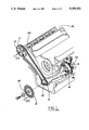
- FIG. 1 is a perspective view of a V-8 engine showing two independently phase shiftable camshafts and crankshaft assembly
- FIGS. 2A, 2B, and 2C show, respectively, a front view of two camshaft data wheels and a crankshaft data wheel;
- FIG. 3 is schematic block diagram of a control circuit for cam phase shifting for two independently phase shiftable camshafts and sequential fuel control
- FIG. 4 is a wave form diagram for the signals generated by the crankshaft and camshaft sensors showing relative timing of the signals without phase shifting.
- FIG. 1 is a perspective of a typical V-8 internal combustion engine showing the locations of a crankshaft data wheel 10 and the right-hand cam data wheel 12 and the left-hand camshaft data wheel 14, as assembled on to the two independent camshafts 20,22.
- the crankshaft data wheel 10 is fixed rotationally relative to the crankshaft 18 and the crankshaft sprocket 9.
- the camshaft data wheels 12,14 are fixed rotationally to their respective camshafts 20,22.
- the camshaft data wheels 12, 14 are rotationally coupled to the camshaft sprockets 11, 13 respectively.
- These camshaft sprockets 11, 13 rotate about the same axis as their respective camshafts 20, 22 and are in turn rotationally coupled to the crankshaft sprocket 9.
- Adjacent to the crankshaft data wheel 10 is a magnetic sensor 60, fixed relative to the engine 16, that generates an electrical pulse as each tooth 24 of the crankshaft data wheel 10 passes.
- the right-hand camshaft data wheel 12 has four camshaft position markers 26, 28, 30,32 affixed to one of its faces, spaced radially around the periphery, one unique marker for a specific cylinder.
- the right-hand and left-hand designations herein are merely used as a convenient way to distinguish one camshaft from another.
- the cam sensor 34 is fixed relative to the engine 16.
- the material of these markers 26, 28, 30, 32 will be such that a sensor 34, such as a hall sensor, will be able to detect the leading and trailing edges as they pass.
- the right-hand camshaft data wheel 12 will rotate clockwise as shown in this figure.
- the radial length of the marker 26 can vary significantly, so long as the radial length is sufficient for the sensor 34 to read the marker 26 as it passes.
- each consecutive marker 26, 28, 30, 32 is 90° ahead of the next one.
- the leading edge 36 of marker 26 is 90° ahead of the leading edge 38 of marker 28, and so on.
- Each marker 26, 28, 30, 32 has a unique angular width, to permit the sensor to accurately distinguish the rotational position of the right-hand camshaft data wheel 12.
- marker 26 is 15° wide A; marker 28 is 20° wide B; marker 30 is 25° wide C; and marker 32 is 30° wide D.
- the markers are positioned so that the leading edge of the signal generated by sensor 34 is advanced 10° from the rotational position of the crankshaft when its associated piston is at top dead center.
- the left-hand camshaft data wheel 14 as shown in FIGS. 2-C and 3 has four camshaft position markers 40, 42, 44, 46 and one cylinder identification marker 48. Each is similar in radial length to the markers on the right-hand camshaft data wheel 12. This radial length is sufficient for the left-hand camshaft sensor 54, affixed relative to the engine block 16, to read these markers.
- the markers 40, 42, 44, 46, 48 are spaced radially around the periphery and rotate clockwise as shown in this figure with four markers for cylinders, and one for cylinder identification. The leading edge of each of the camshaft position markers 40, 42, 44, 46 are 90° ahead of the next one, respectively.
- the leading edge 50 of marker 40 is 90° ahead of the leading edge 52 of marker 42.
- the leading edge of the cylinder identification marker 48 is half-way, i.e. 45°, between the leading edge of the camshaft position marker 40 and the camshaft position marker 46 to distinguish it from the other markers.
- Each of these camshaft position markers 40, 42, 44, 46 has a unique angular width.
- marker 40 is 15° wide E; marker 42 is 20° wide F; marker 44 is 25° wide G; marker 46 is 35° wide H; and the cylinder identification marker 48 is 15° wide.
- crankshaft data wheel 10 shown in FIGS. 2-B and 3, contains at its periphery an arrangement of 35 gear teeth 24 spaced 10° apart so as to leave a 20° gap 58 between two of the teeth 24.
- the crankshaft sensor 60 which is fixed relative to the engine 16, senses the teeth 24, and generates a corresponding crankshaft position signal.
- the crankshaft sensor 60 is electrically connected 64 to the electronic distributorless ignition system (EDIS) microprocessor 62.
- This EDIS microprocessor 62 is electrically connected to both transmit signals on electrical lead 66 and receive signals on electrical lead 68 from the electronic engine control (EEC) microprocessor 70.
- the EDIS microprocessor 62 is electrically connected by lead 74 to an ignition spark mechanism 72.
- Both the right-hand 34 and left-hand 54 camshaft sensors are electrically connected by means of electrical leads 76,78, respectively, to the EEC microprocessor 70.
- the EEC microprocessor 70 is also electrically connected via leads 80,82 to a right-hand cam phase actuator mechanism 84 and a left-hand cam phase actuator mechanism 86, respectively.
- the cam phase actuator mechanisms 84,86 are coupled between the corresponding camshafts 20,22 and camshaft sprockets 11,13. This can be accomplished through the use of a suitable cam phase shifting mechanism such as shown and described in U.S. Pat. No. 5,117,784 Schechter et al, which is incorporated herein by reference, preferably with an added feature of an ability to return to a predetermined default position if and when the crankshaft position signal is lost.
- the EEC microprocessor 70 is electrically connected by electrical lead 88 to the fuel injectors 90.
- crankshaft sensor 60 magnetically senses each crankshaft data wheel tooth 24 and produces a crankshaft signal which is electrically transmitted via lead 64 to the EDIS microprocessor 62 resulting in the signals shown in FIG. 4.
- the EDIS microprocessor 62 converts the signal 92 into a profile ignition pick-up (PIP) signal 94, also shown in FIG. 4, thereafter electrically transmitted via lead 66 to the EEC microprocessor 70.
- PIP profile ignition pick-up
- the right-hand camshaft sensor 34 senses the cam data wheel markers 26, 28, 30, 32 and produces the resulting electric variable cam timing (VCT) signal 96 as shown in FIG. 4, which is electrically transmitted via lead 76 to the EEC microprocessor 70, and electrically transmitted via lead 102 to the EDIS microprocessor 62.
- VCT electric variable cam timing
- the left-hand camshaft data wheel 14 senses the cam sprocket markers 40, 42, 44, 46 and produces a resulting VCT signal 98, as shown in FIG. 4. Yet, unlike the right-hand side, the signal 98 also contains in this a component due to the cylinder identification marker 48. This overall signal 98 is then electrically transmitted via lead 78 to the EEC microprocessor 70, and electrically transmitted via lead 104 to the EDIS microprocessor 62.
- the pulses 41, 43, 45, 47, 49 correspond to the left-hand cam markers 40, 42, 44, 46, 48, respectively.
- the VCT signals 96, 98 that are received by the EDIS microprocessor 62 are used to calculate the sequential fuel injection timing and ignition timing during start-up. This is accomplished in the EDIS microprocessor 62, by counting the number of crankshaft signal 92 pulses per VCT signal 96, 98 pulse.
- the variable width VCT pulses 27, 29, 31, 33 have unique widths and thus the number of crankshaft signal 92 pulses will be different for each, correlating to each individual cylinder. Therefore, the engine position and velocity can be determined quickly after the starter switch 112 is activated.
- the EEC microprocessor 70 compares and synthesizes the PIP signal 94, the right-hand VCT signal 96, and the left-hand VCT and CID signal 98 to calculate the needed phase shift of either the left-hand camshaft 22, or right-hand camshaft 20, or both. If the phase shift of the right-hand camshaft 20 is necessary, then the EEC microprocessor 70 transmits an electric signal via lead 80 to the right-hand cam phase actuator mechanism 84 which physically shifts the phase of the right-hand camshaft 20. Likewise, if the phase shift is needed for the left-hand camshaft 20, the same process takes place with respect to the left-hand cam actuator mechanism 86. In addition, the EEC microprocessor 70 uses the signals 94, 96, 98 to calculate the timing necessary for sequential fuel injection and electrically transmits this via lead 88 to the sequential fuel injectors 90.
- the EEC microprocessor 70 transmits a signal via lead 68 to the EDIS microprocessor 62 which in turn uses that signal to calculate the ignition timing and send an ignition timing signal via lead 74 to the spark mechanism 72.
- the microprocessor 62 will in turn electrically transmit, via lead 67, a failure signal to the EEC microprocessor 70.
- the EEC microprocessor 62 will then use VCT signals 96, 98 to create a signal and transmit this to the EDIS microprocessor 62 which will use this via lead 68 to determine the ignition timing signal to electrically transmit via lead 74 to the ignition mechanism 72.
- VCT signals 96, 98 to create a signal and transmit this to the EDIS microprocessor 62 which will use this via lead 68 to determine the ignition timing signal to electrically transmit via lead 74 to the ignition mechanism 72.
- the EEC microprocessor 70 will send cam phase signals via leads 80,82 to return the camshafts 20,22 to their predetermined default position and no phase shifting is possible until the crankshaft sensor 60 is again working properly.
- FIG. 4 shows the pulsewaves relative to each other for various signals in the system in one complete engine cycle (for an 8 cylinder engine with 2 independently phase shiftable camshafts), with the camshaft faces in their baseline position.
- the pulses 27, 29, 31, 33 of varying widths correspond to the right-hand cam markers 26, 28, 30, 32, respectively.
- the pulses 41, 43, 45, 47, 49 correspond to the left-hand cam markers 40, 42, 44, 46, 48, respectively.
- the present invention can determine camshaft 20,22 rotational position phase relative to the crankshaft 18 whenever one of the cam pulses from the signals 96,98 correspond to the pulses of the PIP pulse 94, thus increasing the accuracy of determining camshaft 20,22 position relative to the crankshaft 18.
- the only change is to use optical sensors instead of the magnetic sensors 34,54 with a corresponding change in the camshaft data wheel markers 26, 28, 30, 32, 42, 44, 46, 48 to readable optical differences between them and the camshaft data wheels 12,14, rather than a magnetic variation.
- camshaft sensors 34, 54 may be oriented radially relative to the camshaft data wheels 12, 14, respectively, rather than perpendicular to the plane of rotation of the data wheels 24, 54.
- the variable width markers 26, 28, 30, 32, 40, 42, 44, 46, 48 would then be placed along the periphery of the data wheels 12, 14 to allow the camshaft sensors 34, 54 to read them. Numerous other rearrangements, modifications and substitutions are possible without departing from the scope of the claims hereafter.
Landscapes
- Engineering & Computer Science (AREA)
- Mechanical Engineering (AREA)
- General Engineering & Computer Science (AREA)
- Chemical & Material Sciences (AREA)
- Combustion & Propulsion (AREA)
- Physics & Mathematics (AREA)
- Electromagnetism (AREA)
- General Physics & Mathematics (AREA)
- Combined Controls Of Internal Combustion Engines (AREA)
- Valve Device For Special Equipments (AREA)
- Electrical Control Of Air Or Fuel Supplied To Internal-Combustion Engine (AREA)
- Valve-Gear Or Valve Arrangements (AREA)
- Ignition Installations For Internal Combustion Engines (AREA)
- Electrical Control Of Ignition Timing (AREA)
- Output Control And Ontrol Of Special Type Engine (AREA)
Abstract
Description
Claims (10)
Priority Applications (4)
| Application Number | Priority Date | Filing Date | Title |
|---|---|---|---|
| US07/919,339 US5209202A (en) | 1992-07-27 | 1992-07-27 | Multiple functions cam sensing |
| DE69327273T DE69327273T2 (en) | 1992-07-27 | 1993-07-19 | Multi-functional camshaft position transmitter |
| EP93305667A EP0581508B1 (en) | 1992-07-27 | 1993-07-19 | Multiple functions cam sensing |
| JP5184089A JPH06200816A (en) | 1992-07-27 | 1993-07-26 | Setting method and system of optimum phase of crankshaft relative to camshaft and operating method of internal combustion engine thereby |
Applications Claiming Priority (1)
| Application Number | Priority Date | Filing Date | Title |
|---|---|---|---|
| US07/919,339 US5209202A (en) | 1992-07-27 | 1992-07-27 | Multiple functions cam sensing |
Publications (1)
| Publication Number | Publication Date |
|---|---|
| US5209202A true US5209202A (en) | 1993-05-11 |
Family
ID=25441914
Family Applications (1)
| Application Number | Title | Priority Date | Filing Date |
|---|---|---|---|
| US07/919,339 Expired - Lifetime US5209202A (en) | 1992-07-27 | 1992-07-27 | Multiple functions cam sensing |
Country Status (4)
| Country | Link |
|---|---|
| US (1) | US5209202A (en) |
| EP (1) | EP0581508B1 (en) |
| JP (1) | JPH06200816A (en) |
| DE (1) | DE69327273T2 (en) |
Cited By (43)
| Publication number | Priority date | Publication date | Assignee | Title |
|---|---|---|---|---|
| US5329904A (en) * | 1992-08-04 | 1994-07-19 | Nippondenso Co., Ltd. | Engine control apparatus for discriminating cylinders |
| US5333577A (en) * | 1992-09-25 | 1994-08-02 | Nippondenso Co., Ltd. | Variable valve operation timing control device |
| US5357932A (en) * | 1993-04-08 | 1994-10-25 | Ford Motor Company | Fuel control method and system for engine with variable cam timing |
| FR2706530A1 (en) * | 1993-06-16 | 1994-12-23 | Bosch Gmbh Robert | Method and apparatus for adjusting the angular position of a camshaft |
| DE4335805A1 (en) * | 1993-10-20 | 1995-04-27 | Bayerische Motoren Werke Ag | Circuit arrangement for detecting at least one marking assigned to an angle of rotation (angle of revolution) position of a shaft |
| DE4340614A1 (en) * | 1993-11-29 | 1995-06-01 | Bayerische Motoren Werke Ag | Adjustment of camshaft relative to crankshaft |
| GB2284685A (en) * | 1993-11-22 | 1995-06-14 | Ford Motor Co | Detecting the angular position of a variable postion camshaft |
| US5460134A (en) * | 1991-12-18 | 1995-10-24 | Robert Bosch Gmbh | Transmitter arrangement for cylinder identification in an internal combustion engine having n cylinders |
| US5462022A (en) * | 1993-11-29 | 1995-10-31 | Nippondenso Co., Ltd. | Valve timing control apparatus having cylinder discriminating function |
| US5549091A (en) * | 1992-09-30 | 1996-08-27 | Honda Giken Kogyo Kabushiki Kaisha | 4-cycle engine and magnetic sensor |
| US5572973A (en) * | 1992-12-16 | 1996-11-12 | Robert Bosch Gmbh | Method for cylinder identification in an internal combustion engine when idling |
| US5671145A (en) * | 1994-05-17 | 1997-09-23 | Siemens Aktiengesellschaft | Method for emergency control of an internal combustion engine |
| US5736633A (en) * | 1997-01-16 | 1998-04-07 | Ford Global Technologies, Inc. | Method and system for decoding of VCT/CID sensor wheel |
| US5829412A (en) * | 1994-12-15 | 1998-11-03 | Robert Bosch Gmbh | System for controlling an internal combustion engine |
| US5860406A (en) * | 1996-04-10 | 1999-01-19 | Caterpillar Inc. | Engine timing apparatus and method of operating same |
| US6101993A (en) * | 1999-02-19 | 2000-08-15 | Ford Global Technologies, Inc. | Variable cam timing control system and method |
| US6277045B1 (en) * | 1999-12-08 | 2001-08-21 | Daimlerchrysler Corporation | Thin profile cam sprocket with integrated timing target |
| US6295964B1 (en) | 2000-08-10 | 2001-10-02 | Ford Global Technologies, Inc. | End-feed variable cam timing oil supply and control module |
| US20020157641A1 (en) * | 2001-04-20 | 2002-10-31 | Koji Sakakibara | Engine control system with cam sensor |
| US6474278B1 (en) | 2000-11-20 | 2002-11-05 | General Motors Corporation | Global cam sensing system |
| US20030000501A1 (en) * | 2000-11-16 | 2003-01-02 | Klaus Bayerle | Method for injecting fuel during the start phase of an intrenal combustion engine |
| US6505128B1 (en) | 1999-11-02 | 2003-01-07 | Unisia Jecs Corporation | Apparatus and method for judging cylinders of an engine |
| US6536389B1 (en) | 2002-04-16 | 2003-03-25 | Ford Global Technologies, Inc. | Adaptive control of cylinder valve timing in internal combustion engine |
| US20030106524A1 (en) * | 2001-12-06 | 2003-06-12 | Glugla Christopher Paul | Intake manifold pressure control for variable displacement engines |
| US20030168044A1 (en) * | 2002-02-01 | 2003-09-11 | Ingolf Rupp | Method of determining the crankshaft position of an internal combustion engine |
| US20030178005A1 (en) * | 2002-03-12 | 2003-09-25 | Fewell Roy J. | Processor controlled discharge ignition with fixed firing angle at startup |
| US6637390B1 (en) * | 2002-05-23 | 2003-10-28 | Delphi Technologies, Inc. | Apparatus and method for measuring cam phaser locking pin position |
| US20030230263A1 (en) * | 2002-06-17 | 2003-12-18 | Earl Ekdahl | VCT cam timing system utilizing calculation of intake phase for dual dependent cams |
| US6675772B1 (en) * | 2002-09-19 | 2004-01-13 | Ford Global Technologies, Llc | Method and system for controlling an internal combustion engine when such engine loses a primary crankshaft position sensor |
| US20040074289A1 (en) * | 2002-06-24 | 2004-04-22 | Siemens Aktiengesellschaft | Method and device for determining the initial angle position of an internal combustion engine |
| US6732709B1 (en) | 2002-12-06 | 2004-05-11 | Caterpillar Inc | Dynamic engine timing control |
| US20040134472A1 (en) * | 2003-01-15 | 2004-07-15 | Duty Mark J. | System and method for determining purge valve flow tolerance |
| US6853184B2 (en) | 2002-12-02 | 2005-02-08 | Honeywell International Inc. | Methods and systems for utilizing a ring magnet for magnetic sensing applications |
| US6868812B2 (en) * | 2000-11-28 | 2005-03-22 | Unisia Jecs Corporation | Valve timing control system for internal combustion engine |
| US20050252469A1 (en) * | 2002-12-18 | 2005-11-17 | Aft Atlas Fahrzeugtechnik Gmbh | Arrangement for adjusting the angle of rotation of a camshaft relative to a crankshaft |
| US20060052932A1 (en) * | 2004-09-08 | 2006-03-09 | Meyer Garth M | Method and system for determining cylinder position with an internal combustion engine |
| US20080172160A1 (en) * | 2003-09-05 | 2008-07-17 | Borgwarner Inc. | Method to measure VCT phase by tracking the absolute angular positions of the camshaft and the crankshaft |
| US20090093939A1 (en) * | 2007-10-09 | 2009-04-09 | Ford Global Technologies, Llc | Valve Control Synchronization and Error Detection in an Electronic Valve Actuation Engine System |
| US20100263438A1 (en) * | 2009-04-15 | 2010-10-21 | Gm Global Technology Operations, Inc. | Camshaft position measurement and diagnosis |
| US20110048350A1 (en) * | 2006-08-25 | 2011-03-03 | Borgwarner Inc. | Variable force solenoid with integrated position sensor |
| US9683468B2 (en) | 2014-06-24 | 2017-06-20 | Ford Global Technologies, Llc | Camshaft positioning |
| US20200165942A1 (en) * | 2018-11-26 | 2020-05-28 | Borgwarner Inc. | Electrically-actuated variable camshaft timing device controller |
| CN113931742A (en) * | 2021-09-29 | 2022-01-14 | 上海海事大学 | A kind of diesel engine connecting rod bearing temperature monitoring device and monitoring method |
Families Citing this family (4)
| Publication number | Priority date | Publication date | Assignee | Title |
|---|---|---|---|---|
| JP3979161B2 (en) * | 2001-04-20 | 2007-09-19 | 株式会社デンソー | Engine control device |
| JP3789848B2 (en) * | 2002-05-02 | 2006-06-28 | 三菱電機株式会社 | Valve timing control device for internal combustion engine |
| US6955145B1 (en) * | 2004-04-15 | 2005-10-18 | Borgwarner Inc. | Methods and apparatus for receiving excessive inputs in a VCT system |
| KR101438315B1 (en) * | 2013-03-29 | 2014-09-04 | 쌍용자동차 주식회사 | cam shaft gear for automobile |
Citations (10)
| Publication number | Priority date | Publication date | Assignee | Title |
|---|---|---|---|---|
| US4365602A (en) * | 1979-12-21 | 1982-12-28 | Volkswagenwerk Aktiengesellschaft | Timing signal generator for ignition and fuel injection systems in a 4-stroke internal combustion engine |
| US4459968A (en) * | 1983-05-27 | 1984-07-17 | Ford Motor Company | Ignition system |
| US4485784A (en) * | 1981-06-30 | 1984-12-04 | New Nippon Electric Co., Ltd. | An engine ignition control circuit having a failsafe for a crank angle sensor |
| US4615318A (en) * | 1984-10-06 | 1986-10-07 | Hitachi, Ltd | Ignition apparatus for internal combustion engine |
| US4873958A (en) * | 1987-08-28 | 1989-10-17 | Fuji Jukogyo Kabushiki Kaisha | Engine ignition timing control system |
| US4924830A (en) * | 1988-04-30 | 1990-05-15 | Fuji Jukogyo Kabushiki Kaisha | Cylinder discriminating system for an automotive engine |
| US4926822A (en) * | 1988-04-28 | 1990-05-22 | Fuji Jukogyo Kabushiki Kaisha | Control system for an automotive engine |
| US4953531A (en) * | 1988-09-27 | 1990-09-04 | Fuji Jukogyo Kabushiki Kaisha | Crank angle detector for an engine |
| US5117784A (en) * | 1991-05-03 | 1992-06-02 | Ford Motor Company | Internal combustion engine camshaft phaseshift control system |
| US5144920A (en) * | 1989-02-10 | 1992-09-08 | Imp Renzo | Automatic timing governor between crankshaft and camshafts, operating by means of actuators on the shaft connecting chain |
Family Cites Families (2)
| Publication number | Priority date | Publication date | Assignee | Title |
|---|---|---|---|---|
| JPH0694854B2 (en) * | 1983-04-08 | 1994-11-24 | 株式会社ゼクセル | Fuel injection advance measuring device for diesel engine |
| US4909194A (en) * | 1989-07-20 | 1990-03-20 | Siemens-Bendix Automotive Electronics L.P. | Modular position controller for variable valve timing |
-
1992
- 1992-07-27 US US07/919,339 patent/US5209202A/en not_active Expired - Lifetime
-
1993
- 1993-07-19 DE DE69327273T patent/DE69327273T2/en not_active Expired - Fee Related
- 1993-07-19 EP EP93305667A patent/EP0581508B1/en not_active Expired - Lifetime
- 1993-07-26 JP JP5184089A patent/JPH06200816A/en active Pending
Patent Citations (10)
| Publication number | Priority date | Publication date | Assignee | Title |
|---|---|---|---|---|
| US4365602A (en) * | 1979-12-21 | 1982-12-28 | Volkswagenwerk Aktiengesellschaft | Timing signal generator for ignition and fuel injection systems in a 4-stroke internal combustion engine |
| US4485784A (en) * | 1981-06-30 | 1984-12-04 | New Nippon Electric Co., Ltd. | An engine ignition control circuit having a failsafe for a crank angle sensor |
| US4459968A (en) * | 1983-05-27 | 1984-07-17 | Ford Motor Company | Ignition system |
| US4615318A (en) * | 1984-10-06 | 1986-10-07 | Hitachi, Ltd | Ignition apparatus for internal combustion engine |
| US4873958A (en) * | 1987-08-28 | 1989-10-17 | Fuji Jukogyo Kabushiki Kaisha | Engine ignition timing control system |
| US4926822A (en) * | 1988-04-28 | 1990-05-22 | Fuji Jukogyo Kabushiki Kaisha | Control system for an automotive engine |
| US4924830A (en) * | 1988-04-30 | 1990-05-15 | Fuji Jukogyo Kabushiki Kaisha | Cylinder discriminating system for an automotive engine |
| US4953531A (en) * | 1988-09-27 | 1990-09-04 | Fuji Jukogyo Kabushiki Kaisha | Crank angle detector for an engine |
| US5144920A (en) * | 1989-02-10 | 1992-09-08 | Imp Renzo | Automatic timing governor between crankshaft and camshafts, operating by means of actuators on the shaft connecting chain |
| US5117784A (en) * | 1991-05-03 | 1992-06-02 | Ford Motor Company | Internal combustion engine camshaft phaseshift control system |
Cited By (62)
| Publication number | Priority date | Publication date | Assignee | Title |
|---|---|---|---|---|
| US5460134A (en) * | 1991-12-18 | 1995-10-24 | Robert Bosch Gmbh | Transmitter arrangement for cylinder identification in an internal combustion engine having n cylinders |
| US5329904A (en) * | 1992-08-04 | 1994-07-19 | Nippondenso Co., Ltd. | Engine control apparatus for discriminating cylinders |
| US5333577A (en) * | 1992-09-25 | 1994-08-02 | Nippondenso Co., Ltd. | Variable valve operation timing control device |
| US5549091A (en) * | 1992-09-30 | 1996-08-27 | Honda Giken Kogyo Kabushiki Kaisha | 4-cycle engine and magnetic sensor |
| US5572973A (en) * | 1992-12-16 | 1996-11-12 | Robert Bosch Gmbh | Method for cylinder identification in an internal combustion engine when idling |
| US5357932A (en) * | 1993-04-08 | 1994-10-25 | Ford Motor Company | Fuel control method and system for engine with variable cam timing |
| FR2706530A1 (en) * | 1993-06-16 | 1994-12-23 | Bosch Gmbh Robert | Method and apparatus for adjusting the angular position of a camshaft |
| DE4335805A1 (en) * | 1993-10-20 | 1995-04-27 | Bayerische Motoren Werke Ag | Circuit arrangement for detecting at least one marking assigned to an angle of rotation (angle of revolution) position of a shaft |
| GB2284685B (en) * | 1993-11-22 | 1998-03-18 | Ford Motor Co | Detecting the angular position of a variable position camshaft |
| GB2284685A (en) * | 1993-11-22 | 1995-06-14 | Ford Motor Co | Detecting the angular position of a variable postion camshaft |
| US5548995A (en) * | 1993-11-22 | 1996-08-27 | Ford Motor Company | Method and apparatus for detecting the angular position of a variable position camshaft |
| US5462022A (en) * | 1993-11-29 | 1995-10-31 | Nippondenso Co., Ltd. | Valve timing control apparatus having cylinder discriminating function |
| DE4340614C2 (en) * | 1993-11-29 | 1998-01-22 | Bayerische Motoren Werke Ag | Device for rotating a camshaft relative to the crankshaft in a motor vehicle internal combustion engine |
| DE4340614A1 (en) * | 1993-11-29 | 1995-06-01 | Bayerische Motoren Werke Ag | Adjustment of camshaft relative to crankshaft |
| US5671145A (en) * | 1994-05-17 | 1997-09-23 | Siemens Aktiengesellschaft | Method for emergency control of an internal combustion engine |
| US5829412A (en) * | 1994-12-15 | 1998-11-03 | Robert Bosch Gmbh | System for controlling an internal combustion engine |
| US5860406A (en) * | 1996-04-10 | 1999-01-19 | Caterpillar Inc. | Engine timing apparatus and method of operating same |
| US5736633A (en) * | 1997-01-16 | 1998-04-07 | Ford Global Technologies, Inc. | Method and system for decoding of VCT/CID sensor wheel |
| US6101993A (en) * | 1999-02-19 | 2000-08-15 | Ford Global Technologies, Inc. | Variable cam timing control system and method |
| US6505128B1 (en) | 1999-11-02 | 2003-01-07 | Unisia Jecs Corporation | Apparatus and method for judging cylinders of an engine |
| US6277045B1 (en) * | 1999-12-08 | 2001-08-21 | Daimlerchrysler Corporation | Thin profile cam sprocket with integrated timing target |
| US6295964B1 (en) | 2000-08-10 | 2001-10-02 | Ford Global Technologies, Inc. | End-feed variable cam timing oil supply and control module |
| US6769412B2 (en) * | 2000-11-16 | 2004-08-03 | Siemens Aktiengesellschaft | Method for injecting fuel during the start phase of an internal combustion engine |
| US20030000501A1 (en) * | 2000-11-16 | 2003-01-02 | Klaus Bayerle | Method for injecting fuel during the start phase of an intrenal combustion engine |
| US6474278B1 (en) | 2000-11-20 | 2002-11-05 | General Motors Corporation | Global cam sensing system |
| US6868812B2 (en) * | 2000-11-28 | 2005-03-22 | Unisia Jecs Corporation | Valve timing control system for internal combustion engine |
| US20020157641A1 (en) * | 2001-04-20 | 2002-10-31 | Koji Sakakibara | Engine control system with cam sensor |
| US6679223B2 (en) * | 2001-04-20 | 2004-01-20 | Denso Corporation | Engine control system with cam sensor |
| US6817336B2 (en) | 2001-12-06 | 2004-11-16 | Ford Global Technologies, Llc | Intake manifold pressure control for variable displacement engines |
| US20030106524A1 (en) * | 2001-12-06 | 2003-06-12 | Glugla Christopher Paul | Intake manifold pressure control for variable displacement engines |
| US20030168044A1 (en) * | 2002-02-01 | 2003-09-11 | Ingolf Rupp | Method of determining the crankshaft position of an internal combustion engine |
| US6895931B2 (en) * | 2002-02-01 | 2005-05-24 | Robert Bosch Gmbh | Method of determining the crankshaft position of an internal combustion engine |
| WO2003078830A1 (en) * | 2002-03-12 | 2003-09-25 | R.E. Phelon Company, Inc. | Processor controlled discharge ignition with fixed firing angle at startup |
| US20030178005A1 (en) * | 2002-03-12 | 2003-09-25 | Fewell Roy J. | Processor controlled discharge ignition with fixed firing angle at startup |
| US6799557B2 (en) | 2002-03-12 | 2004-10-05 | R. E. Phelon Company, Inc. | Processor controlled discharge ignition with fixed firing angle at startup |
| US6536389B1 (en) | 2002-04-16 | 2003-03-25 | Ford Global Technologies, Inc. | Adaptive control of cylinder valve timing in internal combustion engine |
| US6637390B1 (en) * | 2002-05-23 | 2003-10-28 | Delphi Technologies, Inc. | Apparatus and method for measuring cam phaser locking pin position |
| US20030230263A1 (en) * | 2002-06-17 | 2003-12-18 | Earl Ekdahl | VCT cam timing system utilizing calculation of intake phase for dual dependent cams |
| US6745732B2 (en) * | 2002-06-17 | 2004-06-08 | Borgwarner Inc. | VCT cam timing system utilizing calculation of intake phase for dual dependent cams |
| US20040074289A1 (en) * | 2002-06-24 | 2004-04-22 | Siemens Aktiengesellschaft | Method and device for determining the initial angle position of an internal combustion engine |
| US7047127B2 (en) * | 2002-06-24 | 2006-05-16 | Siemens Aktiengesellschaft | Method and device for determining the initial angle position of an internal combustion engine |
| US6675772B1 (en) * | 2002-09-19 | 2004-01-13 | Ford Global Technologies, Llc | Method and system for controlling an internal combustion engine when such engine loses a primary crankshaft position sensor |
| US6853184B2 (en) | 2002-12-02 | 2005-02-08 | Honeywell International Inc. | Methods and systems for utilizing a ring magnet for magnetic sensing applications |
| US6732709B1 (en) | 2002-12-06 | 2004-05-11 | Caterpillar Inc | Dynamic engine timing control |
| US7146947B2 (en) * | 2002-12-18 | 2006-12-12 | Aft Atlas Fahrzeugtechnik Gmbh | Arrangement for adjusting the angle of rotation of a camshaft relative to a crankshaft |
| US20050252469A1 (en) * | 2002-12-18 | 2005-11-17 | Aft Atlas Fahrzeugtechnik Gmbh | Arrangement for adjusting the angle of rotation of a camshaft relative to a crankshaft |
| US6830039B2 (en) * | 2003-01-15 | 2004-12-14 | Daimlerchrysler Corporation | System and method for determining purge valve flow tolerance |
| US20040134472A1 (en) * | 2003-01-15 | 2004-07-15 | Duty Mark J. | System and method for determining purge valve flow tolerance |
| US20080172160A1 (en) * | 2003-09-05 | 2008-07-17 | Borgwarner Inc. | Method to measure VCT phase by tracking the absolute angular positions of the camshaft and the crankshaft |
| US20060052932A1 (en) * | 2004-09-08 | 2006-03-09 | Meyer Garth M | Method and system for determining cylinder position with an internal combustion engine |
| US7058500B2 (en) * | 2004-09-08 | 2006-06-06 | Ford Global Technologies, Llc | Method and system for determining cylinder position with an internal combustion engine |
| US20110048350A1 (en) * | 2006-08-25 | 2011-03-03 | Borgwarner Inc. | Variable force solenoid with integrated position sensor |
| US7865290B2 (en) | 2007-10-09 | 2011-01-04 | Ford Global Technologies, Llc | Valve control synchronization and error detection in an electronic valve actuation engine system |
| US20090093939A1 (en) * | 2007-10-09 | 2009-04-09 | Ford Global Technologies, Llc | Valve Control Synchronization and Error Detection in an Electronic Valve Actuation Engine System |
| CN101876279A (en) * | 2009-04-15 | 2010-11-03 | 通用汽车环球科技运作公司 | Camshaft position measurement and diagnosis |
| US20100263438A1 (en) * | 2009-04-15 | 2010-10-21 | Gm Global Technology Operations, Inc. | Camshaft position measurement and diagnosis |
| US7984644B2 (en) * | 2009-04-15 | 2011-07-26 | GM Global Technology Operations LLC | Camshaft position measurement and diagnosis |
| CN101876279B (en) * | 2009-04-15 | 2013-08-14 | 通用汽车环球科技运作公司 | Camshaft position measurement and diagnosis |
| US9683468B2 (en) | 2014-06-24 | 2017-06-20 | Ford Global Technologies, Llc | Camshaft positioning |
| US20200165942A1 (en) * | 2018-11-26 | 2020-05-28 | Borgwarner Inc. | Electrically-actuated variable camshaft timing device controller |
| CN113931742A (en) * | 2021-09-29 | 2022-01-14 | 上海海事大学 | A kind of diesel engine connecting rod bearing temperature monitoring device and monitoring method |
| CN113931742B (en) * | 2021-09-29 | 2024-03-19 | 上海海事大学 | Diesel engine connecting rod bearing temperature monitoring device and monitoring method |
Also Published As
| Publication number | Publication date |
|---|---|
| EP0581508B1 (en) | 1999-12-15 |
| JPH06200816A (en) | 1994-07-19 |
| EP0581508A2 (en) | 1994-02-02 |
| DE69327273D1 (en) | 2000-01-20 |
| EP0581508A3 (en) | 1997-09-03 |
| DE69327273T2 (en) | 2000-04-13 |
Similar Documents
| Publication | Publication Date | Title |
|---|---|---|
| US5209202A (en) | Multiple functions cam sensing | |
| US5245968A (en) | System to determine cam phase and cylinder identification for a variable cam timing engine | |
| KR100238735B1 (en) | Transmitter appangement for cylinder recognition in an internal combustion engine with n cylinders | |
| US5469823A (en) | Sensor arrangement for rapid cylinder detection in a multi-cylinder internal combustion engine | |
| US6752009B2 (en) | Encoded crank position sensor | |
| US6474278B1 (en) | Global cam sensing system | |
| US4700305A (en) | Position displacement and speed sensor system, particularly for combination with an automotive engine control computer | |
| US4787355A (en) | Crank angle detecting system for an internal combustion engine | |
| US5860406A (en) | Engine timing apparatus and method of operating same | |
| EP1141532B1 (en) | Apparatus in a combustion engine | |
| KR20010032397A (en) | Phase recognition device | |
| US4959996A (en) | Control signal generator for an internal combustion engine | |
| JP3786269B2 (en) | Crank angle detection device for internal combustion engine | |
| NZ258815A (en) | Electronic ignition and fuel injection system, using top-dead-centre signal and flywheel tooth sensor | |
| US20010006344A1 (en) | Method of and device for detecting angular position of a rotatable machine part | |
| JP2813210B2 (en) | Cylinder identification device for internal combustion engines | |
| US6588404B1 (en) | Redundant sensor with cylinder shutdown | |
| US20020157649A1 (en) | Method for synchronizing an internal combustion engine based on the angular position of a rotating part | |
| JP3089997B2 (en) | Cylinder identification system for a multi-cylinder internal combustion engine | |
| EP1334267B1 (en) | Camless engine with crankshaft position feedback | |
| US11512676B2 (en) | Detection apparatus and control apparatus | |
| JP3959950B2 (en) | Engine control information detection device | |
| JP2570442B2 (en) | Cylinder identification device for internal combustion engine | |
| US4917064A (en) | Method of and apparatus for generating cylinder discriminating signal in distributor for internal combustion engine | |
| JPH0130622Y2 (en) |
Legal Events
| Date | Code | Title | Description |
|---|---|---|---|
| AS | Assignment |
Owner name: FORD MOTOR COMPANY A CORP. OF DE. Free format text: ASSIGNMENT OF ASSIGNORS INTEREST.;ASSIGNORS:MAURER, JAMES B.;CZEKALA, MICHAEL D.;MRJOIAN, MARC G.;REEL/FRAME:006269/0065 Effective date: 19920717 |
|
| STCF | Information on status: patent grant |
Free format text: PATENTED CASE |
|
| CC | Certificate of correction | ||
| FPAY | Fee payment |
Year of fee payment: 4 |
|
| FPAY | Fee payment |
Year of fee payment: 8 |
|
| AS | Assignment |
Owner name: FORD GLOBAL TECHNOLOGIES, INC. A MICHIGAN CORPORAT Free format text: ASSIGNMENT OF ASSIGNORS INTEREST;ASSIGNOR:FORD MOTOR COMPANY, A DELAWARE CORPORATION;REEL/FRAME:011467/0001 Effective date: 19970301 |
|
| REMI | Maintenance fee reminder mailed | ||
| FPAY | Fee payment |
Year of fee payment: 12 |
|
| SULP | Surcharge for late payment |
Year of fee payment: 11 |