US5206453A - Ejection module for subammunition container - Google Patents
Ejection module for subammunition container Download PDFInfo
- Publication number
- US5206453A US5206453A US07/766,192 US76619291A US5206453A US 5206453 A US5206453 A US 5206453A US 76619291 A US76619291 A US 76619291A US 5206453 A US5206453 A US 5206453A
- Authority
- US
- United States
- Prior art keywords
- ejecting
- ejection module
- pistons
- gas generator
- ejection
- Prior art date
- Legal status (The legal status is an assumption and is not a legal conclusion. Google has not performed a legal analysis and makes no representation as to the accuracy of the status listed.)
- Expired - Fee Related
Links
- 230000002093 peripheral effect Effects 0.000 claims 1
- 238000002347 injection Methods 0.000 abstract 1
- 239000007924 injection Substances 0.000 abstract 1
- 239000007789 gas Substances 0.000 description 35
- 230000001133 acceleration Effects 0.000 description 3
- 238000010276 construction Methods 0.000 description 3
- 239000003380 propellant Substances 0.000 description 2
- 239000002737 fuel gas Substances 0.000 description 1
- 238000005259 measurement Methods 0.000 description 1
- 238000007789 sealing Methods 0.000 description 1
- 238000000926 separation method Methods 0.000 description 1
Images


Classifications
-
- F—MECHANICAL ENGINEERING; LIGHTING; HEATING; WEAPONS; BLASTING
- F42—AMMUNITION; BLASTING
- F42B—EXPLOSIVE CHARGES, e.g. FOR BLASTING, FIREWORKS, AMMUNITION
- F42B12/00—Projectiles, missiles or mines characterised by the warhead, the intended effect, or the material
- F42B12/02—Projectiles, missiles or mines characterised by the warhead, the intended effect, or the material characterised by the warhead or the intended effect
- F42B12/36—Projectiles, missiles or mines characterised by the warhead, the intended effect, or the material characterised by the warhead or the intended effect for dispensing materials; for producing chemical or physical reaction; for signalling ; for transmitting information
- F42B12/56—Projectiles, missiles or mines characterised by the warhead, the intended effect, or the material characterised by the warhead or the intended effect for dispensing materials; for producing chemical or physical reaction; for signalling ; for transmitting information for dispensing discrete solid bodies
- F42B12/58—Cluster or cargo ammunition, i.e. projectiles containing one or more submissiles
- F42B12/60—Cluster or cargo ammunition, i.e. projectiles containing one or more submissiles the submissiles being ejected radially
Definitions
- the present invention relates to an ejection module for a subammunition container.
- European Patent Document EP 0 169 956 A1 discloses an ejection module of this generic type in which a bomb or a missile with a warhead has two sets of nine subammunitions arranged respectively in two circular patterns disposed one behind the other. Each subammunition has an ejecting piston which is arranged in a cylinder and which can be acted upon by a propellant by means of a pyrotechnic primer inserted on the floor of the cylinder. When the primers are ignited, the subammunitions are driven radially toward the outside by the ejecting pistons. This device can therefore only be used as a bomb in vertical or parabolic flight, the subammunitions covering an approximately circular target area.
- German Patent Document DE-PS 30 48 469 discloses another ejection module in which the subammunition container has several ejection modules with ejection tubes arranged transversely with respect to the direction of flight.
- the munitions canisters are inserted into ejection tubes taking up the whole width of the munitions container and are driven out by a central gas generator like pistons. This arrangement is therefore suitable only for subammunitions adapted to the size of the ejection tubes.
- the ejection module in which subammunitions are situated in front of driving elements actuated by gas generator driven pistons and are ejected transversely to the direction of flight of the munitions container.
- the gas generator may be arranged transversely or longitudinally of the flight direction.
- the principal advantage of the invention is that due to the arrangement of the driving devices, bulky subammunition can also be ejected in an essentially horizontal direction, and are brought to a high ejecting speed with moderate acceleration.
- the ejection module according to the invention it is possible to carry out an almost recoil-free ejection of at least two subammunitions disposed opposite one another.
- a larger target surface can be covered with subammunitions, and the sequence of ejections can be distributed over a longer period of time in horizontal flight.
- the ejection is caused in a known manner by gas pressure from only one gas generator.
- FIG. 1 is a partial sectional view of a first embodiment of an ejection module with a traverse gas generator and a short ejecting piston;
- FIGS. 2 and 3 are views of the ejection module according to FIG. 1 in two different phases of ejection;
- FIG. 4 is a phantom view of the ejection module according to FIG. 1 with only one subammunition;
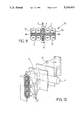
- FIG. 5 is a top view of a second embodiment of an ejection module with a lengthwise gas generator and a short ejecting piston;
- FIG. 6 is a top view of a third embodiment of an ejection module with a lengthwise gas generator and a double ejecting piston;
- FIG. 7 is a lateral view of FIGS. 5 or 6 with a straight ejecting piston without a subammunition
- FIG. 8 is a lateral view of FIGS. 5 or 6 with the ejecting piston in a slight V-position without a subammunition;
- FIG. 9 is a top view of a fourth embodiment of an ejection module with a lengthwise gas generator in a particularly flat construction
- FIG. 10 is a phantom view of the ejection module according to FIG. 9 without a subammunition
- FIG. 11 is a top view of a fifth embodiment of an ejection module with an ejecting piston which extends along the whole width of the module and with the gas generator;
- FIG. 12 is a view of the ejection module according to FIG. 11 during ejection of the subammunition
- FIG. 13 is a phantom view of the ejection module according to FIG. 11 with only one subammunition;
- FIGS. 14 to 16 are three views of a sixth embodiment of an ejection module with a long ejecting piston and a lengthwise gas generator;
- FIGS. 17 and 18 are respectively a top view and a longitudinal view of a seventh embodiment of an ejection module in a flat construction that is free of recoil moments and has four long ejecting pistons and a lengthwise gas generator;
- FIG. 19 is a phantom view of the ejection module according to FIGS. 17 and 18.
- FIGS. 1 to 4 show an ejection module 1 with two mirror-symmetric ejecting pistons 2, which extend approximately half the width of the module, and a gas generator 4 installed inside them.
- the ejecting pistons 2 and the gas generator 4 are disposed transversely with respect to the flight direction of the ejection module indicated by an arrow 3.
- Driving devices 5 for subammunitions (SM's) 7 are connected with the ejecting piston 2.
- Loosely arranged intermediate layers 6 exist between the SM's 7.
- the gas generator 4 is disposed in a pipe 17 (FIG. 2) which is inserted into the ejecting pistons 2 and serves as a guide for these ejecting pistons 2 during the ejecting operation.
- two sealing and sliding elements 8 are arranged between the pipe 17 and the ejecting piston.
- the ejection module 1 is disposed in a munitions container 9 indicated by an interrupted line. In a known manner, the latter is mounted together with a number of ejection modules 1 on an aircraft or missile.
- the ejecting pistons 2 are driven out of the munitions container 9 directly by the gases of the ignited gas generator 4 in the direction of the arrows 11 and 12.
- the SM's 7 detach from the driving devices 5 and the intermediate layers 6 and fly away in the direction of the arrows 13 to 16.
- FIG. 4 The phantom view of FIG. 4 clearly shows the simple construction of this ejection module 1. For a better representation, only one SM 7 is illustrated.
- FIG. 5 is a top view of an ejection module 20 with a gas generator 4 arranged in the flight direction.
- the fuel gases of gas generator 4 flow into a gas pipe 21 which is inserted into each of the respective ejecting pistons 2a and serves as a guide for these ejecting pistons 2a during the ejection operation.
- Driving devices 5, in turn, are connected to the ejecting pistons 2a.
- Only two of the SM's 7 are shown, separated by an intermediate layer 6.
- the carrier structure 9 of the munitions container is indicated by an interrupted line.
- FIG. 6 illustrates an ejection module 25, in which, for example, for large SM's 7, two ejecting pistons 2a respectively are provided which are each connected by way of driving devices 5a.
- the propellant flows from the gas generator 4 into gas pipes 21.
- the ejecting pistons 2a may have a smaller cross-section than those in FIG. 1, so that the overall measurements of the munitions container 9 may be kept small.
- FIGS. 7 and 8 are views of the ejection modules 20 and 25 in the flight direction, the ejection module in FIG. 8 having a slight V-position so that the SM's (not shown)are provided with a vertical speed component during ejection.
- the projection path is increased relative to the ejection height which leads, for example, to wider projecting widths of the SM's.
- the recoil forces which affect the supporting structure are small in the case of small V-positions.
- the ejection model 30 illustrated in FIGS. 9 and 10 has a very flatly constructed solution in which the ejecting pistons and the gas pipes 32 do not have a rotationally symmetrical cross-section, as shown particularly in the phantom view of FIG. 10.
- the ejecting pistons form a structural unit 31 with the driving devices, whereby the driving forces contribute to the stiffening.
- the one end of the structural unit 31 is shown in a sectional view, so that one of the gas pipes 32 segmented into several parallel-acting parts is easily visible.
- the ejecting pistons of the previously described embodiments have a length which is less than half the width of the container modules, in the case of the following embodiments, the ejecting pistons extend along the full width of the ejection modules.
- This arrangement has the advantage of the largest possible accelerating paths; thus, in the case of a slight acceleration, the highest ejecting speeds for the SM's can be achieved.
- FIGS. 11 to 13 show an ejection module 40 in which the gas generator 4 is arranged in parallel to the axes between two ejecting pistons 41 which slide in cylinders 43 and 44. On both ends of the gas generator 4, overflow slots 45 and 46 are arranged through which the gas can act upon the ejecting pistons 41.
- FIGS. 11 and 12 illustrate the SM's 7 and the supporting structure 9 of the munitions container.
- the phantom view of FIG. 13 shows that the driving structures 48 are fastened on both sides in the front to the ejecting pistons 41.
- FIGS. 14 to 16 are three views of an ejection module 50 in which the gas generator 4 can be housed in the longitudinal structure of the munitions container which is not shown here. Gas from the gas generator 4 flows behind the ejecting pistons 41 by way of a central overflow slot 51 and gas duct 52.
- the cylinders 43 and 44 as well as the driving structures 48 correspond to those of FIGS. 11 to 13. The advantage of this arrangement is the slight lateral separation of the ejecting pistons 41 and the resulting low recoil moments.
- FIGS. 17 to 19 show a flatly constructed recoil-moment-free arrangement of an ejection module 60.
- Double ejecting pistons 61 and 62 in a cylinder unit 63, overflow slots 64 and gas ducts 65 are constructed mirror-symmetrically about the axis of the ejection module 60.
- Each of the ejecting pistons 61 and 62 comprises two longitudinal pipes 61a, 61b and 62a, 62b which are connected with one another in piston heads 61c and 62c.
- the gas guides in the piston heads 61c and 62c as well as the gas ducts 65 are constructed to be pressure-compensating so that the same pressure exists in each of the four piston pipes.
- the gas generator 4 is arranged centrally in the flight direction.
- Driving structures 67 are fastened to the piston heads 61c and 62c.
- the ejecting pistons are shown partially slid out for the purpose of a better representation.
Landscapes
- Engineering & Computer Science (AREA)
- Chemical & Material Sciences (AREA)
- Combustion & Propulsion (AREA)
- General Engineering & Computer Science (AREA)
- Feeding, Discharge, Calcimining, Fusing, And Gas-Generation Devices (AREA)
- Toys (AREA)
- Sampling And Sample Adjustment (AREA)
Abstract
Description
Claims (13)
Applications Claiming Priority (2)
| Application Number | Priority Date | Filing Date | Title |
|---|---|---|---|
| DE4033476 | 1990-10-20 | ||
| DE4033476A DE4033476C2 (en) | 1990-10-20 | 1990-10-20 | Ejection module for submunition containers |
Publications (1)
| Publication Number | Publication Date |
|---|---|
| US5206453A true US5206453A (en) | 1993-04-27 |
Family
ID=6416763
Family Applications (1)
| Application Number | Title | Priority Date | Filing Date |
|---|---|---|---|
| US07/766,192 Expired - Fee Related US5206453A (en) | 1990-10-20 | 1991-09-27 | Ejection module for subammunition container |
Country Status (3)
| Country | Link |
|---|---|
| US (1) | US5206453A (en) |
| EP (1) | EP0482421B1 (en) |
| DE (2) | DE4033476C2 (en) |
Cited By (1)
| Publication number | Priority date | Publication date | Assignee | Title |
|---|---|---|---|---|
| US5554815A (en) * | 1993-09-06 | 1996-09-10 | Etienne Lacroix Toux Artifices S.A. | Munition constituting a cartridge-launcher loader, in particular for countermeasure cartridge-launcher on aircraft |
Families Citing this family (2)
| Publication number | Priority date | Publication date | Assignee | Title |
|---|---|---|---|---|
| DE102004059991B4 (en) * | 2004-12-13 | 2007-03-15 | Nico-Pyrotechnik Hanns-Jürgen Diederichs GmbH & Co. KG | irritation body |
| DE102004061658A1 (en) * | 2004-12-22 | 2006-07-13 | Diehl Bgt Defence Gmbh & Co. Kg | Ejecting acceleration sensitive ammunition from a projectile, comprises accelerating the ammunition during primary and secondary phases |
Citations (8)
| Publication number | Priority date | Publication date | Assignee | Title |
|---|---|---|---|---|
| US2979991A (en) * | 1951-10-10 | 1961-04-18 | Martin Co | Rapid firing recoilless bomb projecting device |
| US4172407A (en) * | 1978-08-25 | 1979-10-30 | General Dynamics Corporation | Submunition dispenser system |
| US4307650A (en) * | 1978-07-05 | 1981-12-29 | Messerschmitt-Boelkow-Blohm Gesellschaft Mit Beschraenkter Haftung | Weapons system for the ballistic and guided attack on multiple targets, especially by an aircraft |
| US4750403A (en) * | 1986-01-31 | 1988-06-14 | Loral Corporation | Spin dispensing method and apparatus |
| GB2204388A (en) * | 1984-05-10 | 1988-11-09 | Messerschmitt Boelkow Blohm | Container for dispersing ammunition |
| US4941392A (en) * | 1988-12-22 | 1990-07-17 | Messerschmitt-Boelkow-Blohm Gmbh | Scatter ammunition container |
| US5005481A (en) * | 1989-06-26 | 1991-04-09 | Olin Corporation | Inflatable bladder submunition dispensing system |
| US5014590A (en) * | 1986-10-23 | 1991-05-14 | Messerschmitt-Bolkow-Blohm Gmbh | Device for ejecting submunition |
Family Cites Families (6)
| Publication number | Priority date | Publication date | Assignee | Title |
|---|---|---|---|---|
| NL300029A (en) * | 1962-11-08 | |||
| DE3048469C1 (en) * | 1980-12-22 | 1988-12-15 | Messerschmitt Boelkow Blohm | Cluster munitions container |
| US4455943A (en) * | 1981-08-21 | 1984-06-26 | The Boeing Company | Missile deployment apparatus |
| DE3219535C2 (en) * | 1982-05-25 | 1984-04-05 | Messerschmitt-Bölkow-Blohm GmbH, 8000 München | Missile for dropping cluster munitions |
| FR2557286B1 (en) * | 1983-12-27 | 1986-12-05 | Brandt Armements | MULTIPLE HEAD MILITARY LOAD |
| FR2594219B1 (en) * | 1986-02-13 | 1989-12-15 | Rafaut & Cie | EJECTION DEVICE, PARTICULARLY FOR AMMUNITION |
-
1990
- 1990-10-20 DE DE4033476A patent/DE4033476C2/en not_active Expired - Fee Related
-
1991
- 1991-09-27 US US07/766,192 patent/US5206453A/en not_active Expired - Fee Related
- 1991-10-09 DE DE59107301T patent/DE59107301D1/en not_active Expired - Fee Related
- 1991-10-09 EP EP91117165A patent/EP0482421B1/en not_active Expired - Lifetime
Patent Citations (8)
| Publication number | Priority date | Publication date | Assignee | Title |
|---|---|---|---|---|
| US2979991A (en) * | 1951-10-10 | 1961-04-18 | Martin Co | Rapid firing recoilless bomb projecting device |
| US4307650A (en) * | 1978-07-05 | 1981-12-29 | Messerschmitt-Boelkow-Blohm Gesellschaft Mit Beschraenkter Haftung | Weapons system for the ballistic and guided attack on multiple targets, especially by an aircraft |
| US4172407A (en) * | 1978-08-25 | 1979-10-30 | General Dynamics Corporation | Submunition dispenser system |
| GB2204388A (en) * | 1984-05-10 | 1988-11-09 | Messerschmitt Boelkow Blohm | Container for dispersing ammunition |
| US4750403A (en) * | 1986-01-31 | 1988-06-14 | Loral Corporation | Spin dispensing method and apparatus |
| US5014590A (en) * | 1986-10-23 | 1991-05-14 | Messerschmitt-Bolkow-Blohm Gmbh | Device for ejecting submunition |
| US4941392A (en) * | 1988-12-22 | 1990-07-17 | Messerschmitt-Boelkow-Blohm Gmbh | Scatter ammunition container |
| US5005481A (en) * | 1989-06-26 | 1991-04-09 | Olin Corporation | Inflatable bladder submunition dispensing system |
Cited By (1)
| Publication number | Priority date | Publication date | Assignee | Title |
|---|---|---|---|---|
| US5554815A (en) * | 1993-09-06 | 1996-09-10 | Etienne Lacroix Toux Artifices S.A. | Munition constituting a cartridge-launcher loader, in particular for countermeasure cartridge-launcher on aircraft |
Also Published As
| Publication number | Publication date |
|---|---|
| EP0482421B1 (en) | 1996-01-24 |
| DE4033476C2 (en) | 1994-10-13 |
| DE59107301D1 (en) | 1996-03-07 |
| DE4033476A1 (en) | 1992-04-23 |
| EP0482421A1 (en) | 1992-04-29 |
Similar Documents
| Publication | Publication Date | Title |
|---|---|---|
| US4616567A (en) | Method and apparatus for covering a target area with ammunition | |
| RU2513079C2 (en) | Transport aircraft cargoes carry-and-drop system | |
| WO1979000658A1 (en) | An arrangement for launching interference material | |
| US5005483A (en) | Method for the ejection of sub-munitions and projectile applying said method | |
| US4681013A (en) | Rotary launcher system for an aircraft | |
| US4444117A (en) | Stacked tube submunition dispenser | |
| JP2795537B2 (en) | Missile lateral thrust assembly | |
| US3517584A (en) | Stores ejection means | |
| US7051659B2 (en) | Projectile structure | |
| RU2068169C1 (en) | Process of launching of rocket from aircraft | |
| US5206453A (en) | Ejection module for subammunition container | |
| SE508475C2 (en) | Method and apparatus for spreading combat parts | |
| SE442246B (en) | SET AND DEVICE TO REDUCE BASIC RESISTANCE FOR PROJECTILES | |
| SE452207B (en) | DEVICE FOR COLLECTION OF CYLINDRIC COUNTRY AMUNITATION IN PACKAGES | |
| US5218165A (en) | Pneumatic separation device | |
| RU2175726C1 (en) | Solid-propellant engine boost unit | |
| US4625649A (en) | Projectiles | |
| SE444725B (en) | GRANTE CASTLE FRAMEWORK MUNICIPAL WITH SEPARATED PROJECT BODY AND TARGET WITH DRIVE CHARGING | |
| JP2003114096A (en) | Flying object | |
| SE8701729D0 (en) | PROJECTILE | |
| EP0513153B1 (en) | Hypervelocity sabot | |
| RU182345U1 (en) | A device for separating a group of unmanned aerial vehicles from a carrier aircraft | |
| US5363767A (en) | Stand-off weapons | |
| GB2150091A (en) | Guided munition | |
| CA2019879A1 (en) | Gas generator missile launch system |
Legal Events
| Date | Code | Title | Description |
|---|---|---|---|
| AS | Assignment |
Owner name: MESSERSCHMITT-BOLKOW-BLOHM GMBH, GERMANY Free format text: ASSIGNMENT OF ASSIGNORS INTEREST.;ASSIGNOR:RIEGER, ULRICH;REEL/FRAME:006043/0327 Effective date: 19920124 |
|
| FEPP | Fee payment procedure |
Free format text: PAYOR NUMBER ASSIGNED (ORIGINAL EVENT CODE: ASPN); ENTITY STATUS OF PATENT OWNER: LARGE ENTITY |
|
| FPAY | Fee payment |
Year of fee payment: 4 |
|
| AS | Assignment |
Owner name: LFK-LENKFLUGKOERPERSYSTEME GMBH, GERMANY Free format text: ASSIGNMENT OF ASSIGNORS INTEREST;ASSIGNOR:DAIMLER-BENZ AEROSPACE AG;REEL/FRAME:009883/0794 Effective date: 19981111 |
|
| FEPP | Fee payment procedure |
Free format text: PAYER NUMBER DE-ASSIGNED (ORIGINAL EVENT CODE: RMPN); ENTITY STATUS OF PATENT OWNER: LARGE ENTITY Free format text: PAYOR NUMBER ASSIGNED (ORIGINAL EVENT CODE: ASPN); ENTITY STATUS OF PATENT OWNER: LARGE ENTITY |
|
| FPAY | Fee payment |
Year of fee payment: 8 |
|
| REMI | Maintenance fee reminder mailed | ||
| LAPS | Lapse for failure to pay maintenance fees | ||
| STCH | Information on status: patent discontinuation |
Free format text: PATENT EXPIRED DUE TO NONPAYMENT OF MAINTENANCE FEES UNDER 37 CFR 1.362 |
|
| FP | Lapsed due to failure to pay maintenance fee |
Effective date: 20050427 |