US519620A - Or other furnaces - Google Patents
Or other furnaces Download PDFInfo
- Publication number
- US519620A US519620A US519620DA US519620A US 519620 A US519620 A US 519620A US 519620D A US519620D A US 519620DA US 519620 A US519620 A US 519620A
- Authority
- US
- United States
- Prior art keywords
- furnace
- air
- furnaces
- brickwork
- puddling
- Prior art date
- Legal status (The legal status is an assumption and is not a legal conclusion. Google has not performed a legal analysis and makes no representation as to the accuracy of the status listed.)
- Expired - Lifetime
Links
- 239000011449 brick Substances 0.000 description 7
- 238000002485 combustion reaction Methods 0.000 description 7
- 238000010276 construction Methods 0.000 description 4
- 239000000446 fuel Substances 0.000 description 4
- 239000007789 gas Substances 0.000 description 4
- 238000002791 soaking Methods 0.000 description 4
- 238000003303 reheating Methods 0.000 description 3
- 230000000694 effects Effects 0.000 description 2
- 230000004048 modification Effects 0.000 description 2
- 238000012986 modification Methods 0.000 description 2
- 239000002699 waste material Substances 0.000 description 2
- 210000000481 breast Anatomy 0.000 description 1
- 238000010438 heat treatment Methods 0.000 description 1
- 239000011148 porous material Substances 0.000 description 1
- 230000001737 promoting effect Effects 0.000 description 1
- 239000007787 solid Substances 0.000 description 1
- 239000002918 waste heat Substances 0.000 description 1
Images


Classifications
-
- C—CHEMISTRY; METALLURGY
- C21—METALLURGY OF IRON
- C21C—PROCESSING OF PIG-IRON, e.g. REFINING, MANUFACTURE OF WROUGHT-IRON OR STEEL; TREATMENT IN MOLTEN STATE OF FERROUS ALLOYS
- C21C3/00—Manufacture of wrought-iron or wrought-steel
Definitions
- TN mman. LrrHoGnAPHINa coMPANv.
- FIG- 1E- l Wit/@888648 /Uj/Z-Or; M Q. M, @QW 51mm,f
- My invention relates to the class of furnaces known as puddling, mill, reh eating, and forge furnaces, or the like structures such as gas furnaces and soaking pits into which air can be advantageously admitted in the manner hereinafter described.
- Puddling and reheating furnaces are constructed with walls and roof of solid brickwork, the whole of the air required for the combustion kof the fuel being admitted through the furnace grate.
- the object of my invention is to effect improvementsy in -attaining the same results namely, to utilize the heat which is absorbed into the roof andupper brickwork of the furnaceby heating air which is drawn'through the said brickwork into the furnace by which the brickwork is 6o ⁇ different forms of brick used in the construction of the furnace' or soaking pit.
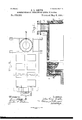
- Figs. 7, 8 and 9 illustrate my invention as applied to 75 a soaking pit, Fig. 9 being a longitudinal s ec, tional view on the line .c a: of Fig. 8, with part of the side wallbrokeu away to show the interstices therein.
- Fig. 10 is an enlarged front elevation partly in section, showing the 8o interstice as formed in the wall.
- a a a are holes in the breast of the furnace into which the outside air is flrst admitted. The air then becomes dilfused among the passages and intersticesb until it reaches the bricks D in which openings d are provided through which the air is discharged into the interior of the furnace just beyond the. furnace bridge e.
- openings d are provided through which the air is discharged into the interior of the furnace just beyond the. furnace bridge e.
- Fig. 3 is the form of brick used at A, Fig. 4, being the form of br1ck used at B, Fig. 5 at C to provide for the holes ct, communicating with the outside air and at C for communicating endwise with thereof; and Fig. 6 at D to provide for the holes cl communicating with the interior of the furnace.
- Any desired number of pores or openings communicating with the internal lnterstices are provided as required to admit outside air both on the outer surface and ou the inner surface to deliver the air so admitted into the interior of the furnace.
- the usual grate is provided below or at the end of the furnace to support the combustion of the fuel as in puddling and reheating furnaces of the ordinary construction.
- f is the usual fire grate which draws in air through the bars in the usual manner to excite the combustion of the fuel for generating gas, and g g g are stoke holes for stoking the fire.
- Figs. 7, 8 and 9 which illustrate my invention as applied to a ⁇ soaking pit it will be observed that the interstices and passages are formed in the side and end walls of the furnace, the air entering in at the openings a and threading its Way along to the air ports h where it combines with the' gases from the gas ports K in the manner required for combustion.
- Z is an annular boiler constructed and erected to serve as the uptake for the products of combustion, the waste heat of which is thereby intercepted and utilized for generating steam.
Landscapes
- Engineering & Computer Science (AREA)
- Chemical & Material Sciences (AREA)
- Manufacturing & Machinery (AREA)
- Materials Engineering (AREA)
- Metallurgy (AREA)
- Organic Chemistry (AREA)
- Furnace Housings, Linings, Walls, And Ceilings (AREA)
Description
. (No Model.)
Patented May 8. 1.894.
- Inventur:
OCW Sfmf),
vVhtneE-.EES
(No Model.) v3 Sheets-Sheet 2.
J. L. SMITH. CONSTRUCTION OT PUDDLING OR OTHER TURNAOES. No. 519,620. Patented May 8, 1894.
lf/Fi-f` N ik e y se bei 7 we: A l .l
Winesses: QL hxga.-
' Attnrrre'ya,
TN: mman. LrrHoGnAPHINa coMPANv.
(No Model.) 3 Sheets-Sheet 3.
J. L. SMITH. CONSTRUCTION OP PUDDLING OR'OTHBR PURNAGES.
No. 519,620. Patented May 8, 1894.
FIG- 1E- l Wit/@888648: /Uj/Z-Or; M Q. M, @QW 51mm,f
- .www
-NITED STATI-s' P..TENT Orifice.5
JOHN LAW SMITH, OF WEST HARTLEPOOL, ENGLAND.
SPECIFICATION forming part of Letters Patent No. 519,620, dated May 8, 1894.
Application filed March 16,1893. Serial No. 466,303. (No model.) Patented in England March 2, 1892, No. 4,106; in France February 2, 1893,11'0. 227,609, and in Belgium February 20, 1893.110. 103,510.
ToaZZ whom, it may concern.'
Be it known that I, JOHN LAW SMITH, a subject of the Queen of Great Britain, residing at West Hartlepool,in the county of Durham, England, have invented certain new and useful Improvements in the Construction of Puddling or other Furnaces, (for which I have obtained patents in Great Britain, No.
`- 4,106, dated March 2, 1892; in France, No.
227,609, dated February 2, 1893, and in Belgium, No. 103,510, dated February 20, 1893;) and I do hereby declare the following to be a full, clear, and exact description of the invention, such as will enable others skilled in the art to which it appertains to make and use the Same.
My invention relates to the class of furnaces known as puddling, mill, reh eating, and forge furnaces, or the like structures such as gas furnaces and soaking pits into which air can be advantageously admitted in the manner hereinafter described.
In describing my invention Ivwill in the first place refer toits application to puddlingand reheatin g furnaces of the usual design. Puddling and reheating furnaces are constructed with walls and roof of solid brickwork, the whole of the air required for the combustion kof the fuel being admitted through the furnace grate. It is found in practice that although the heat generated within the furnace in this manner is sufficient to effect lits intended purpose, a waste of fuel results owing to a proportion of the elements of combustion'passin'g out of the furnace unconsumed and tothe waste of theheat in the upper region of the furnace which impinges upon and -is absorbed into the brickwork of the roof and adjoining parts which in consequence re` is made to serve the useful purpose of heat- 5 0 ingthe incoming air, while the air so admitted serves the useful purpose of keeping the brickwork cool and of promoting a more perfect combustion within the furnace. The object of my invention is to effect improvementsy in -attaining the same results namely, to utilize the heat which is absorbed into the roof andupper brickwork of the furnaceby heating air which is drawn'through the said brickwork into the furnace by which the brickwork is 6o `different forms of brick used in the construction of the furnace' or soaking pit. Figs. 7, 8 and 9 illustrate my invention as applied to 75 a soaking pit, Fig. 9 being a longitudinal s ec, tional view on the line .c a: of Fig. 8, with part of the side wallbrokeu away to show the interstices therein. Fig. 10 is an enlarged front elevation partly in section, showing the 8o interstice as formed in the wall.
In applying my invention to a piiddling or relieating furnace from which its application to furnaces generally will be readily understood I construct the roof and upper brickwork wholly or in-part of lbricks specially molded or constructed for the purposes of myV invention and substantially in the form of which the modifications required in constructing the furnace shown in Figs. 1 and 2 9o are' illustrated in Figs. 3 to 6 inclusive, that is to say, that brickworkfso constructed includes numerous interstices forming tortuous and intersecting passages or ramifications through which outside air is drawn into the 9 5 interior of the furnace on the Well known principle of checker work and with a view of bringing the incoming-air into intimate contact with as large an area of heated brick surface as possible.
Referring to Figs. l and 2 in which the puddling furnace is of the ordinary design and the precise form indicated by the drawings 1s given for the purposes of illustration only, a a a are holes in the breast of the furnace into which the outside air is flrst admitted. The air then becomes dilfused among the passages and intersticesb until it reaches the bricks D in which openings d are provided through which the air is discharged into the interior of the furnace just beyond the. furnace bridge e. As it is essential that the above described nterstices and passages be provided without resorting to brickwork of unusual thickness it will be understood that specially constructed bricks must be used; these special bricks as adapted for the purpose of my invention, take the form shown 1n F1gs. 3 to 6 inclusive, that is to say, the central part of each brick is hollowed out while the ends present the usual faces for surface contact subject to such modification as the general construction of the furnace may require, as for instance, Fig. 3 is the form of brick used at A, Fig. 4, being the form of br1ck used at B, Fig. 5 at C to provide for the holes ct, communicating with the outside air and at C for communicating endwise with thereof; and Fig. 6 at D to provide for the holes cl communicating with the interior of the furnace. Any desired number of pores or openings communicating with the internal lnterstices are provided as required to admit outside air both on the outer surface and ou the inner surface to deliver the air so admitted into the interior of the furnace. In furnaces constructed with my improved porous roofs or .upper walls the usual grate is provided below or at the end of the furnace to support the combustion of the fuel as in puddling and reheating furnaces of the ordinary construction. f is the usual fire grate which draws in air through the bars in the usual manner to excite the combustion of the fuel for generating gas, and g g g are stoke holes for stoking the fire.
Referring to Figs. 7, 8 and 9 which illustrate my invention as applied to a` soaking pit it will be observed that the interstices and passages are formed in the side and end walls of the furnace, the air entering in at the openings a and threading its Way along to the air ports h where it combines with the' gases from the gas ports K in the manner required for combustion. Z is an annular boiler constructed and erected to serve as the uptake for the products of combustion, the waste heat of which is thereby intercepted and utilized for generating steam.
Having thus described my iuvention,`what I claim, and desire to secure by Letters Patent of the United States, is-
1. In a furnace, the combination with a tire chamber; of walls having horizontal air pasing horizontal and vertical air passages there in, the said air passages breaking joints with each other, forming tortuous passages for the air, the lower courses ot openings communt eating with the external air, and the upper courses of openings communicating with the interior of the furnace, substantially as and for the purposes described.
In testimony whereof I affix my signature in presence of two witnesses.
Jol-1N LAW sMrrn.
lVitnesses:
GEORGE J AMES CLARKsoN, EDWARD THOMAS ELcoAT.
Publications (1)
| Publication Number | Publication Date |
|---|---|
| US519620A true US519620A (en) | 1894-05-08 |
Family
ID=2588418
Family Applications (1)
| Application Number | Title | Priority Date | Filing Date |
|---|---|---|---|
| US519620D Expired - Lifetime US519620A (en) | Or other furnaces |
Country Status (1)
| Country | Link |
|---|---|
| US (1) | US519620A (en) |
-
0
- US US519620D patent/US519620A/en not_active Expired - Lifetime
Similar Documents
| Publication | Publication Date | Title |
|---|---|---|
| US566924A (en) | Furnace for steam-generators | |
| US519620A (en) | Or other furnaces | |
| US103651A (en) | Improvement in hot-blast ovens | |
| US248059A (en) | Rumble | |
| US130154A (en) | Improvement in glass-furnaces | |
| US480561A (en) | Brick-kiln | |
| US618218A (en) | barnes | |
| US120378A (en) | Improvement in lime-kilns | |
| US850066A (en) | Kiln. | |
| US240429A (en) | Puddling and heating furnace | |
| US480969A (en) | Waelder | |
| US413247A (en) | Hot-blast stove | |
| US797626A (en) | Furnace. | |
| US988131A (en) | Furnace for melting metals, glass, and the like. | |
| US257574A (en) | Regenerative stove for heating air | |
| US1199016A (en) | Kiln. | |
| US891452A (en) | Blast-heating apparatus for furnaces. | |
| US328389A (en) | Frank wesley dick and james eiley | |
| US285316A (en) | Glass-furnace | |
| US530869A (en) | Furnace | |
| US147159A (en) | Improvement in reverberatory furnaces | |
| US293821A (en) | tower | |
| US783234A (en) | Hot-blast stove. | |
| US1169769A (en) | Hot-air furnace. | |
| US524915A (en) | Regenerative furnace |