US5195700A - Low speed model following velocity command system for rotary wing aircraft - Google Patents
Low speed model following velocity command system for rotary wing aircraft Download PDFInfo
- Publication number
- US5195700A US5195700A US07/751,437 US75143791A US5195700A US 5195700 A US5195700 A US 5195700A US 75143791 A US75143791 A US 75143791A US 5195700 A US5195700 A US 5195700A
- Authority
- US
- United States
- Prior art keywords
- signal
- signal value
- value
- providing
- ground speed
- Prior art date
- Legal status (The legal status is an assumption and is not a legal conclusion. Google has not performed a legal analysis and makes no representation as to the accuracy of the status listed.)
- Expired - Fee Related
Links
- RZVHIXYEVGDQDX-UHFFFAOYSA-N 9,10-anthraquinone Chemical compound C1=CC=C2C(=O)C3=CC=CC=C3C(=O)C2=C1 RZVHIXYEVGDQDX-UHFFFAOYSA-N 0.000 claims abstract description 15
- 230000008859 change Effects 0.000 claims description 29
- 230000004044 response Effects 0.000 claims description 8
- 238000001914 filtration Methods 0.000 claims 2
- 230000001131 transforming effect Effects 0.000 claims 2
- 230000026676 system process Effects 0.000 abstract 1
- 230000006870 function Effects 0.000 description 28
- 230000007704 transition Effects 0.000 description 10
- 238000006073 displacement reaction Methods 0.000 description 4
- 238000010586 diagram Methods 0.000 description 3
- 230000035945 sensitivity Effects 0.000 description 3
- 230000000007 visual effect Effects 0.000 description 3
- 230000003750 conditioning effect Effects 0.000 description 2
- 125000004122 cyclic group Chemical group 0.000 description 2
- 230000005484 gravity Effects 0.000 description 2
- 238000000638 solvent extraction Methods 0.000 description 2
- 230000009466 transformation Effects 0.000 description 2
- 230000001133 acceleration Effects 0.000 description 1
- 238000007792 addition Methods 0.000 description 1
- 238000013459 approach Methods 0.000 description 1
- 238000006243 chemical reaction Methods 0.000 description 1
- 230000003111 delayed effect Effects 0.000 description 1
- 230000001419 dependent effect Effects 0.000 description 1
- 238000005562 fading Methods 0.000 description 1
- 230000001360 synchronised effect Effects 0.000 description 1
- 230000001052 transient effect Effects 0.000 description 1
- 238000009966 trimming Methods 0.000 description 1
Images


Classifications
-
- G—PHYSICS
- G05—CONTROLLING; REGULATING
- G05D—SYSTEMS FOR CONTROLLING OR REGULATING NON-ELECTRIC VARIABLES
- G05D1/00—Control of position, course, altitude or attitude of land, water, air or space vehicles, e.g. using automatic pilots
- G05D1/0055—Control of position, course, altitude or attitude of land, water, air or space vehicles, e.g. using automatic pilots with safety arrangements
- G05D1/0061—Control of position, course, altitude or attitude of land, water, air or space vehicles, e.g. using automatic pilots with safety arrangements for transition from automatic pilot to manual pilot and vice versa
-
- A—HUMAN NECESSITIES
- A61—MEDICAL OR VETERINARY SCIENCE; HYGIENE
- A61P—SPECIFIC THERAPEUTIC ACTIVITY OF CHEMICAL COMPOUNDS OR MEDICINAL PREPARATIONS
- A61P1/00—Drugs for disorders of the alimentary tract or the digestive system
-
- A—HUMAN NECESSITIES
- A61—MEDICAL OR VETERINARY SCIENCE; HYGIENE
- A61P—SPECIFIC THERAPEUTIC ACTIVITY OF CHEMICAL COMPOUNDS OR MEDICINAL PREPARATIONS
- A61P11/00—Drugs for disorders of the respiratory system
-
- A—HUMAN NECESSITIES
- A61—MEDICAL OR VETERINARY SCIENCE; HYGIENE
- A61P—SPECIFIC THERAPEUTIC ACTIVITY OF CHEMICAL COMPOUNDS OR MEDICINAL PREPARATIONS
- A61P11/00—Drugs for disorders of the respiratory system
- A61P11/08—Bronchodilators
-
- A—HUMAN NECESSITIES
- A61—MEDICAL OR VETERINARY SCIENCE; HYGIENE
- A61P—SPECIFIC THERAPEUTIC ACTIVITY OF CHEMICAL COMPOUNDS OR MEDICINAL PREPARATIONS
- A61P13/00—Drugs for disorders of the urinary system
- A61P13/02—Drugs for disorders of the urinary system of urine or of the urinary tract, e.g. urine acidifiers
-
- A—HUMAN NECESSITIES
- A61—MEDICAL OR VETERINARY SCIENCE; HYGIENE
- A61P—SPECIFIC THERAPEUTIC ACTIVITY OF CHEMICAL COMPOUNDS OR MEDICINAL PREPARATIONS
- A61P15/00—Drugs for genital or sexual disorders; Contraceptives
-
- A—HUMAN NECESSITIES
- A61—MEDICAL OR VETERINARY SCIENCE; HYGIENE
- A61P—SPECIFIC THERAPEUTIC ACTIVITY OF CHEMICAL COMPOUNDS OR MEDICINAL PREPARATIONS
- A61P9/00—Drugs for disorders of the cardiovascular system
-
- A—HUMAN NECESSITIES
- A61—MEDICAL OR VETERINARY SCIENCE; HYGIENE
- A61P—SPECIFIC THERAPEUTIC ACTIVITY OF CHEMICAL COMPOUNDS OR MEDICINAL PREPARATIONS
- A61P9/00—Drugs for disorders of the cardiovascular system
- A61P9/10—Drugs for disorders of the cardiovascular system for treating ischaemic or atherosclerotic diseases, e.g. antianginal drugs, coronary vasodilators, drugs for myocardial infarction, retinopathy, cerebrovascula insufficiency, renal arteriosclerosis
-
- A—HUMAN NECESSITIES
- A61—MEDICAL OR VETERINARY SCIENCE; HYGIENE
- A61P—SPECIFIC THERAPEUTIC ACTIVITY OF CHEMICAL COMPOUNDS OR MEDICINAL PREPARATIONS
- A61P9/00—Drugs for disorders of the cardiovascular system
- A61P9/12—Antihypertensives
-
- G—PHYSICS
- G05—CONTROLLING; REGULATING
- G05D—SYSTEMS FOR CONTROLLING OR REGULATING NON-ELECTRIC VARIABLES
- G05D1/00—Control of position, course, altitude or attitude of land, water, air or space vehicles, e.g. using automatic pilots
- G05D1/08—Control of attitude, i.e. control of roll, pitch, or yaw
- G05D1/0808—Control of attitude, i.e. control of roll, pitch, or yaw specially adapted for aircraft
- G05D1/0858—Control of attitude, i.e. control of roll, pitch, or yaw specially adapted for aircraft specially adapted for vertical take-off of aircraft
Definitions
- This invention relates to flight control systems for rotary wing aircraft, and more particularly to control systems with model following control laws that operate in a velocity command mode.
- pilot inputs are used to set a main rotor blade tip path which results in a certain aircraft attitude, and velocity vector (i.e., a flight path).
- a control system leads to the aforementioned high workload the pilot experiences while hovering in degraded visual environments.
- the pilot if the pilot is hovering above a particular spot and desires to move the aircraft to another location and hover, he inputs a lateral cyclic input which starts the aircraft moving towards the new hover location. As the aircraft approaches the new desired hover location, the pilot provides an arresting cyclic input to bring the aircraft to a stop over the new desired hover location.
- Such a positioning system results in a high workload being placed on the pilot since he may have to iterate several times before being able to enter a hover over the new desired location. Furthermore, the difficulty of entering hover over a precise location is increased under degraded visual flight conditions in which an attack helicopter must be fully capable of operating.
- An object of the present invention is to reduce the amount of pilot work load required to manually fly a rotary winged aircraft at low airspeeds.
- Another object of the present invention is to allow small precise changes to aircraft position with low pilot workload.
- Another object of the present invention is to provide an aircraft flight control system which operates a velocity command model in response to pilot inputs at low airspeeds.
- Yet another object of the present invention is to generate aircraft commands necessary to provide a ground referenced velocity response which is proportional to lateral or longitudinal inputs on a sidearm controller.
- a further object of the present invention is to provide a rotary winged aircraft flight control system which transitions smoothly in and out of the velocity command mode.
- a model following flight control system for a rotary winged aircraft operates in a velocity command mode at low airspeeds to control aircraft velocity in response to pitch and roll stick commands from the pilot.
- the present invention allows a rotary winged aircraft pilot to make precise changes to an aircraft's position while the aircraft is operating at low airspeeds, thereby reducing the pilot workload required to make such a precise change.
- FIG. 1 is a pictorial illustration of a rotary winged aircraft in which the present invention may be used;
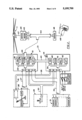
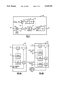
- FIG. 2 is a block diagram of the model following flight control system of the present invention
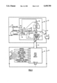
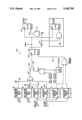
- FIG. 3 is a schematic illustration of one portion of the embodiment of FIG. 1;
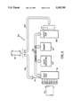
- FIG. 4 is a block diagram of one embodiment of one of the system components illustrated in FIG. 2;
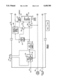
- FIG. 5 is a schematic illustration of the functional elements of the embodiment of FIG. 4;
- FIG. 6 is a companion schematic illustration of FIG. 5;
- FIG. 7 is a schematic illustration of further functional details of the embodiment of FIG. 4;
- FIG. 8A is a schematic illustration of still further functional details of the embodiment of FIG. 4;
- FIG. 8B is a schematic illustration of still further functional details of the embodiment of FIG. 4.
- FIG. 9 is a schematic illustration of still further functional details of the embodiment of FIG. 4.
- FIG. 1 is a pictorial illustration of a helicopter embodiment 10 of a rotary winged aircraft in which the present invention may be used.
- the helicopter includes a main rotor assembly 11 and tail rotor assembly 12.
- the helicopter flight control system of the present invention 21 is a model following control system which shapes the pilot's sidearm controller and displacement stick commands through an "inverse vehicle model" to produce a desired aircraft response.
- the system includes a Primary Flight Control System (PFCS) 22 and an Automatic Flight Control System (AFCS) 24.
- the PFCS receives displacement command output signals from a displacement collective stick 26 on line 27 and the AFCS receives the collective stick discrete output signals on a line 28.
- the PFCS and AFCS each receive the force output command signals of a force type four axis sidearm controller 29, on lines 30, and the aircraft's sensed parameter signals from sensors 31, on lines 32.
- the pilot command signals on lines 27, 28, and 30 and the sensed parameter signals on lines 32 are shown consolidated within trunk lines 33 and 34 in the PFCS and AFCS, respectively.
- the PFCS and AFCS each contain control channel logic for controlling the yaw, pitch, roll and lift axes of the aircraft.
- these logic modules are shown by blocks 35-38 for the PFCS and blocks 39-42 for the AFCS.
- the PFCS provides rotor command signals and the AFCS logic provides conditioning and/or trimming of the PFCS four axis logic functions.
- the PFCS and AFCS logic modules interconnect through bus 43.
- the PFCS and AFCS use a model following algorithm in each control axis to provide rotor command signals on output lines 44 to a main rotor mixing function 45 which commands displacement of mechanical servos 46 and linkages 47 to control the tip path plane of the main rotor 11.
- Command signals are also provided on lines 44 to the helicopter's tail rotor servos 48 which control the thrust of the tail rotor 12 through linkages 49.
- the sensed parameter signals from sensors 31, on lines 32, provide the PFCS and AFCS with the aircraft's angular rate and attitude response to the rotor command signals.
- FIG. 3 is a partial schematic section of FIG. 2, illustrating the functional interconnection of the PFCS 22 and AFCS 24 pitch logic modules 36 and 40, respectfully.
- the PFCS pitch logic module 36 receives a pitch axis command signal on line 50, provided through trunk lines 33 and lines 30, from the sidearm controller 29 (FIG. 2).
- the sidearm controller is a four axis sidearm controller in which the pitch axis command signal is generated by the pilot's imparting a longitudinal force on the sidearm controller.
- the pitch command signal is presented to the input of pitch rate model circuitry 52 (e.g.
- a first order lag filter with selected radian/sec signal gain that provides a desired pitch rate signal on a line 54 indicative of the desired rate of change for the aircraft attitude about the pitch axis.
- Selection of the pitch rate model order of magnitude is dependant on the dynamics of the aircraft and the pitch response desired.
- the desired pitch rate signal on line 54 is presented simultaneously to: the input of a pitch-axis, vehicle inverse model 56, a summing junction 58, and the bus 43 to the AFCS pitch logic module 40.
- the inverse model 56 receives the aircraft's actual airspeed from sensors 31, through lines 32 and trunk 33, as a sensed airspeed signal on line 60.
- the inverse model 56 is a Z-transform model, which may be embodied as a first order lead filter with instantaneous voltage gain and time constant characteristics which vary with the magnitude of the sensed airspeed signal on line 60.
- the cascaded pitch rate model 52 and inverse model 56 provide a feedforward path for the sidearm control signal on line 50.
- the feedforward, inverse Z transform model provides the primary control input to the main rotor assembly 11 (FIG. 1) which causes the helicopter 10 (FIG. 1) to pitch at a rate set by a desired pitch rate command signal on a line 62.
- This desired pitch rate signal represents the main rotor command necessary to achieve the desired pitch-axis rate of change of the aircraft for each pilot commanded maneuver.
- the summing function 58 sums the desired pitch rate signal on line 54 (from the pitch rate model 52) with the aircraft's actual pitch rate, received (from sensors 31, through lines 32 and trunk 33) as a sensed pitch rate signal on line 64, to provide a pitch rate error signal on line 65.
- the rate error signal is amplified in a rate gain stage and presented to one input of a second summing junction 66.
- the junction 66 also receives the desired pitch rate command signal on line 62 from the inverse model 56, and a pitch rate modifying signal on a line 68 from a rate and magnitude limiter 70.
- the limiter 70 which receives a nonlimited version of the modifying pitch rate signal on a line 71 (through bus 43) from the AFCS pitch logic module 40, limits the pitch rate modifying signal magnitude and rate of change to predetermined.
- the resulting sum signal is provided on the output line 72 of the PFCS pitch logic module 36, and presented through the PFCS output trunk lines 44 to the main rotor servos (46, FIG. 1).
- the magnitude and rate of change of the pitch rate modifying signal from the AFCS is a function of the aircraft pitch attitude error.
- the aircraft pitch attitude error is the second of two feedback loops around the main rotor command signal; the first being the pitch rate error signal on line 65.
- the pitch rate modifying signal is a calculated value provided by a model following algorithm within the AFCS, based on the actual aircraft response to the rotor command signal.
- the pitch rate modifying signal modifies the magnitude and rate of change of the main rotor command signal.
- the AFCS pitch logic module 40 receives the following sensed aircraft parameters through trunk line 34: actual airspeed (line 60), actual yaw rate (line 64), pitch attitude (line 86), bank angle (PHI) (line 87), roll rate (line 88), lateral acceleration (line 89), heading (line 90), longitudinal ground speed (line 91), and lateral ground speed (line 92).
- the best mode embodiment of the AFCS is as a microprocessor based electronic control system in which the algorithms of the AFCS logic modules (39-42, FIG. 1) reside in executable program listings stored in memory.
- FIG. 4 shows the architecture of a microprocessor based AFCS 24.
- the desired pitch rate signal on line 54 is received from input lines 93 included within the lines 43 interconnecting the AFCS and PFCS.
- the sensed aircraft parameter signals on lines 60, 64, and 86-92 are received from the AFCS input trunk line 34, at an AFCS input port 94.
- the input port 94 which may include an analog- to-digital converter, a frequency-to-digital convertor, and such other signal conditioning functions known to those skilled in the art as being required to transform the input signals to digital signal format.
- the input port is connected through an address/data bus 95 to a microprocessor 96 (e.g., Intel 80286, Motorola 68020), memory means 97 (including RAM, UVPROM, EEPROM), and an output port 98.
- the output port may comprise a digital-to-analog converter, a parallel- to-serial convertor, a discrete output driver, and such other signal conversion functions known to those skilled in the art as being required to transform the AFCS digital signal format to that required by the control system (21, FIG. 1).
- the output port lines, including the line 71 to the PFCS pitch logic module 36, are presented through lines 99 to the interconnecting lines 43.
- FIG. 5 is illustrated a block diagram of a portion of the AFCS pitch control logic resident in the memory 97, and which executes in the microprocessor 96.
- the present invention is also applicable to control of the AFCS roll logic module 41 with only changes to the applicable roll signals.
- the desired pitch rate command from the PFCS is input on the line 54 to a Body-to-Euler Transformation 102 which also receives the actual vehicle pitch rate, PHI on the line 86.
- the transformation provides a commanded pitch rate signal on a line 104 that has been transformed from a reference about the aircraft body axes to a reference about inertial axes.
- FIG. 8A is a detailed illustration of the logic of the transform.
- the commanded pitch rate signal is input to a pitch attitude model 118 (e.g., an integrator) which integrates over time, and provides a desired pitch attitude signal on a line 120.
- a pitch attitude model 118 e.g., an integrator
- the desired pitch attitude signal is input to a washout filter 122 (i.e., derivative/lag filter with a 2 second time constant), which provides a washed out signal on a line 124 to a summer 126, and a velocity command model 128.
- the summer 126 receives: the pitch attitude signal THETA on the line 86, an attitude bias from a trim map 127, and the signal on the line 124 to provide a washed out error signal on a line 130 to a transient free switch (TFS) 132.
- TFS transient free switch
- the desired pitch attitude signal on the line 120 is also input to a summing function 134 which receives the actual pitch attitude signal THETA, and provides a pitch attitude error signal on a line 136 to the TFS 132.
- the TFS provides a smooth transition of its output signal when the discrete signal HHSW1 changes. That is, rather than instantaneously switching its output signal on a line 140 between the signals on the lines 130,136, the TFS linearly transitions between the two signals when HHSW1 changes state, providing a smooth transition of the TFS output provided on the line 140.
- An explanation of the velocity command model is now in order.
- FIG. 7 is an illustration of the velocity command model 128.
- the washed signal on the line 124 is provided to a switch 150 whose position is dependent upon whether velocity command mode is engaged. If velocity command is engaged the switch 150 is placed in the closed position allowing the washed out signal to pass along a line 152 to a summing function 154. Note, when the pilot applies a change in force to the sidearm controller 29 in the direction the pilot desires the aircraft 10 to move, the washed out signal on the line 124 is non-zero.
- the summing function 154 also receives a feedback signal on a line 156, and provides a difference signal on a line 158 to an integrator with limits 160.
- the difference signal is integrated over time and an integrated signal is provided on a line 162 to a gravity gain 164.
- the gravity gain provides a product in units of velocity to a sensitivity gain 166 whose value sets the sensitivity of the model 128.
- the sensitivity gain provides a velocity command signal on a line 167.
- the integrated signal on the line 162 is also input to a feedback gain 168 which provides a signal to a limit function 170.
- the limit function provides a limited feedback signal on a line 172 which is input to a switch 174 responsive to a discrete signal PHHINS on a line 176.
- the feedback path (162,172,156) acts to washout the integrator when no force is being imparted on the sidearm controller (i.e., the pilot is requesting zero velocity) to ensure there are no steady state velocity commands.
- the value of the feedback gain sets the time constant of the first order lag created by providing the feedback path around the integrator 160.
- FIG. 9 is an illustration of control logic 180 for the various discrete signals used for switching and event triggering.
- the logic receives commands from the sidearm, controller 29 via the lines 30.
- Comparison functions 182,184 each judge the sidearm control commands to determine if the pilot is providing either a pitch command or a roll command. If the pilot is not providing a pitch command, the comparator 182 provides a signal on a line 186 which is set, otherwise the signal is cleared.
- Comparator 184 operates in a similar manner but judges if a roll command is being input via the sidearm controller. If roll input is not being provided provided the comparator 184 sets a signal on a line 188; otherwise the signal is cleared.
- Magnitude comparators 190,192 receive the longitudinal ground speed signal and the lateral ground speed signal respectively, and each compares the magnitude to the speeds to a threshold value of 5 feet/sec. If the magnitude of the longitudinal ground speed is less than 5 feet/sec, the comparator 190 sets a signal on a line 194. Similarly, if the magnitude of lateral ground speed is less than 5 feet/sec., comparator 192 sets a signal on a line 194. Each comparator clears its respective output if the magnitude of its input signal exceeds 5 feet/sec.
- the signals from comparators 182,184,186 and 192 are all input an AND gate 198 which provides an output on line 200 to a two input AND gate 202.
- the two input AND gate also receives a signal from a NOR gate 204 which is cleared if either pitch velocity hold or roll velocity hold is engaged.
- the second AND gate provides a signal on a line 206 to a latch 208. If the signal on the line 206 is set, the output of the latch HHSW1 on the line 133 is set if the reset of the latch on a line 210 is cleared.
- the latch reset input has priority over the set input.
- the signal on the line 210 is set if the magnitude of either the longitudinal ground speed or the lateral ground speed is greater than 8.5 feet/sec as judged by comparators 212,214, thus clearing HHSW1 on the line 133.
- the circuit combination 204,202,208 insures that the velocity command mode cannot be engaged if currently disengaged, while roll or pitch velocity hold is engaged.
- the TF switch 132 provides the signal on the line 140 to a Euler-to-Body transform 220 which transforms the selected error signal on the line 140 which is in terms of Euler axes, back to aircraft body axes.
- the operation of the transform involves straight mathematics as shown.
- the transform 220 provides a transformed error signal on a line 222 to a proportional compensator 224 having a gain function 226 and a limiting function 228 which are cascaded to provide a signal on a line 226.
- the velocity command model 128 provides its output signal on the line 167 to a summing function 228 which also receives the longitudinal ground speed signal on the line 91.
- the summing function 228 provides a signal on a line 230 which is indicative of the longitudinal ground speed error, i.e., it represents the difference between the output signal from the velocity command model and the actual longitudinal ground speed.
- the longitudinal ground speed error is input to a track/hold function 232 which is controlled by HHSW1 on the line 133. When HHSW1 is cleared the function operates in track mode allowing the signal on the line 230 to pass to 232, and when set the function holds the past value on the output line.
- the track/hold function in used to smooth the transition in and out of velocity command mode by holding its output signal on a line 234 constant while a fade function 235 fades the longitudinal speed error signal out when velocity command mode is disengaged (i.e., HHSW1 transitions from set to clear).
- the fade function allows for a smooth transition on the fade output signal on a line 236 by fading the signal on the line in and out over a period of time (e.g., 3 seconds) as the system transitions in and out velocity command, depending upon the conditions shown in FIG. 8.
- the fade function 235 provides the signal on the line 236 to a summing function 238, which also receives a signal on a line 240.
- the longitudinal ground speed signal on the line 91 is also input to a synchronizer 242 which is responsive to the discrete signal PVSELND which is a delayed version of the pitch attitude hold engaged signal.
- PVSELND discrete signal
- PVELSND is set when pitch velocity hold is engaged, and conversely it is cleared when pitch velocity hold is disengaged.
- the synchronizer 242 continuously stores the value of the longitudinal ground speed signal on the line 91, and provides an output signal on a line 244 which is equal to zero.
- the synchronizer When PVELSND transitions from clear to set, indicating that pitch velocity hold has been engaged, the synchronizer begins to provide a signal on the line 244 which is indicative of the difference between the current value of the signal on the line 91, and stored value within the synchronizer, which represents the signal on the line when PVELSND transitioned from clear to set.
- the synchronized signal is input to a fade function 246 whose operation is controlled by the inverted version of the velocity command mode enable signal HHSW1. Therefore, the fade function 246 fades in the signal on the line when velocity command mode is disengaged (i.e., HHSW1 transitions from set to clear), and fades out the signal on the line 244 upon engaging the velocity command mode.
- the summing function takes the difference of the signals on lines 236,240 and provides a difference signal to a proportional and integral compensator 248.
- the compensator provides a signal on a line 250 which is summed with the signal on the line 226 by the summing function 154 to provide the nonlimited pitch modifying command signal on the line 71.
- the present invention may be incorporated with a hover hold system an example of which is co-pending application Ser. No. 07/518,593 filed May 3, 1990, entitled "Hover Position Hold System for Rotary Winged Aircraft".
- This allows the present invention to act as a bias to the hover hold input signal to the mixer, where the bias amount is indicative of the new desired aircraft hover position.
- the present invention has been illustrated in an exemplary embodiment of a microprocessor based electronic control system, one skilled in the art will appreciate that the present invention can be implemented in electronic hardware without the use of a microprocessor. Furthermore, it should be understood that the partitioning of the tasks between the PFCS and the AFCS for the purposes of the present invention is not necessary, rather the partitioning represents the system design conventionally done for a flight control system due to the reliability concerns of placing the complete flight control system in a single electronic package. It should also be noted that the present invention is clearly not limited to attack helicopters, but rather the present invention has applicability to all rotary winged aircraft which seek the advantages of a velocity command mode while operating at low aircraft ground speeds.
Landscapes
- Health & Medical Sciences (AREA)
- Engineering & Computer Science (AREA)
- Bioinformatics & Cheminformatics (AREA)
- General Health & Medical Sciences (AREA)
- Animal Behavior & Ethology (AREA)
- Veterinary Medicine (AREA)
- Public Health (AREA)
- Chemical & Material Sciences (AREA)
- Chemical Kinetics & Catalysis (AREA)
- General Chemical & Material Sciences (AREA)
- Medicinal Chemistry (AREA)
- Nuclear Medicine, Radiotherapy & Molecular Imaging (AREA)
- Organic Chemistry (AREA)
- Pharmacology & Pharmacy (AREA)
- Life Sciences & Earth Sciences (AREA)
- Aviation & Aerospace Engineering (AREA)
- Physics & Mathematics (AREA)
- Automation & Control Theory (AREA)
- Heart & Thoracic Surgery (AREA)
- General Physics & Mathematics (AREA)
- Cardiology (AREA)
- Radar, Positioning & Navigation (AREA)
- Remote Sensing (AREA)
- Pulmonology (AREA)
- Urology & Nephrology (AREA)
- Endocrinology (AREA)
- Reproductive Health (AREA)
- Vascular Medicine (AREA)
- Control Of Position, Course, Altitude, Or Attitude Of Moving Bodies (AREA)
- Control Of Electric Motors In General (AREA)
- Feedback Control In General (AREA)
- Toys (AREA)
Abstract
Description
Claims (10)
Priority Applications (10)
| Application Number | Priority Date | Filing Date | Title |
|---|---|---|---|
| US07/751,437 US5195700A (en) | 1991-08-28 | 1991-08-28 | Low speed model following velocity command system for rotary wing aircraft |
| AU25981/92A AU655845B2 (en) | 1991-08-28 | 1992-08-21 | Low speed model following velocity command system for rotary wing aircraft |
| JP50521993A JP3308533B2 (en) | 1991-08-28 | 1992-08-21 | Low speed model following speed command system for rotary wing aircraft. |
| CA002116565A CA2116565C (en) | 1991-08-28 | 1992-08-21 | Low speed model following velocity command system for rotary wing aircraft |
| PCT/US1992/006962 WO1993005462A1 (en) | 1991-08-28 | 1992-08-21 | Low speed model following velocity command system for rotary wing aircraft |
| KR1019940700623A KR100235272B1 (en) | 1991-08-28 | 1992-08-21 | Low speed model following velocity command system for rotary wing aircraft |
| EP92920165A EP0601123B1 (en) | 1991-08-28 | 1992-08-21 | Low speed model following velocity command system for rotary wing aircraft |
| ES92920165T ES2078753T3 (en) | 1991-08-28 | 1992-08-21 | SPEED COMMAND SYSTEM FOLLOWING A LOW SPEED MODEL FOR ROTATING WING AIRCRAFT. |
| DE69204071T DE69204071T2 (en) | 1991-08-28 | 1992-08-21 | Model-assisted speed control at low speeds for rotary wing aircraft. |
| IL10297792A IL102977A (en) | 1991-08-28 | 1992-08-28 | Low speed model following velocity command system for rotary wing aircraft |
Applications Claiming Priority (1)
| Application Number | Priority Date | Filing Date | Title |
|---|---|---|---|
| US07/751,437 US5195700A (en) | 1991-08-28 | 1991-08-28 | Low speed model following velocity command system for rotary wing aircraft |
Publications (1)
| Publication Number | Publication Date |
|---|---|
| US5195700A true US5195700A (en) | 1993-03-23 |
Family
ID=25021980
Family Applications (1)
| Application Number | Title | Priority Date | Filing Date |
|---|---|---|---|
| US07/751,437 Expired - Fee Related US5195700A (en) | 1991-08-28 | 1991-08-28 | Low speed model following velocity command system for rotary wing aircraft |
Country Status (10)
| Country | Link |
|---|---|
| US (1) | US5195700A (en) |
| EP (1) | EP0601123B1 (en) |
| JP (1) | JP3308533B2 (en) |
| KR (1) | KR100235272B1 (en) |
| AU (1) | AU655845B2 (en) |
| CA (1) | CA2116565C (en) |
| DE (1) | DE69204071T2 (en) |
| ES (1) | ES2078753T3 (en) |
| IL (1) | IL102977A (en) |
| WO (1) | WO1993005462A1 (en) |
Cited By (32)
| Publication number | Priority date | Publication date | Assignee | Title |
|---|---|---|---|---|
| US5431084A (en) * | 1992-05-19 | 1995-07-11 | United Technologies Corporation | Helicopter integrated fire and flight control having azimuth and pitch control |
| US5465212A (en) * | 1993-12-23 | 1995-11-07 | United Technologies Corporation | Helicopter integrated fire and flight control having a pre-launch and post-launch maneuver director |
| US5553817A (en) * | 1994-05-03 | 1996-09-10 | United Technologies Corporation | Turn coordination inhibit for rotary wing aircraft control system |
| US5553812A (en) * | 1994-06-03 | 1996-09-10 | United Technologies Corporation | Inertial velocity command system |
| US5617316A (en) * | 1995-03-15 | 1997-04-01 | Sikorsky Aircraft Corporation | Maintaining attitude error constant in Euler singularity protection |
| US5816533A (en) * | 1995-07-27 | 1998-10-06 | Eurocopter | Method and device for reducing the vibration generated on the structure of a helicopter |
| US5895012A (en) * | 1996-04-04 | 1999-04-20 | Eurocopter France | Method and device for reducing the effect of the vibration generated by the driveline of a helicopter |
| US6076024A (en) * | 1998-04-29 | 2000-06-13 | Sikorsky Aircraft Corporation | Earth-referenced wind adjustment for hovering aircraft |
| US6145428A (en) * | 1998-03-31 | 2000-11-14 | Sikorsky Aircraft Corporation | Integrated fire and flight control system for controlling the angle of attack of a rotary wing aircraft |
| FR2793765A1 (en) * | 1999-05-18 | 2000-11-24 | Eurocopter France | Rotor control for helicopter has sensors to control actuators differentially dependent on flight regime |
| US6648269B2 (en) | 2001-12-10 | 2003-11-18 | Sikorsky Aircraft Corporation | Trim augmentation system for a rotary wing aircraft |
| US20060054737A1 (en) * | 2004-09-14 | 2006-03-16 | The Boeing Company | Tandem rotor wing rotational position control system |
| FR2899562A1 (en) * | 2006-04-05 | 2007-10-12 | Eurocopter France | DEVICE FOR CONTROLLING FLIGHT OF A GIRAVION |
| US20080249672A1 (en) * | 2007-04-03 | 2008-10-09 | Igor Cherepinsky | Altitude and acceleration command altitude hold algorithm for rotorcraft with large center of gravity range |
| US20090047636A1 (en) * | 2005-10-12 | 2009-02-19 | Filip Van Biervliet | Method to Control The Movements of a Flight Simulator and Flight Simulator Implementing such method |
| US20120068007A1 (en) * | 2010-09-16 | 2012-03-22 | Eurocopter | Rotary wing aircraft provided with propulsion means, and a method applied by said aircraft |
| US20140027565A1 (en) * | 2012-02-10 | 2014-01-30 | Merlin Technology, Inc. | Rotorcraft advanced autopilot control arrangement and methods |
| US20140191079A1 (en) * | 2013-01-04 | 2014-07-10 | Bell Helicopter Textron Inc. | Disconnecting a Rotor |
| US9150308B2 (en) | 2012-02-10 | 2015-10-06 | Merlin Technology, Inc. | Rotorcraft autopilot system, components and methods |
| US20150375850A1 (en) * | 2014-06-30 | 2015-12-31 | Airbus Helicopters | Flight control system and method for a rotary wing aircraft, enabling it to maintain either track or heading depending on its forward speed |
| US9304516B2 (en) | 2011-01-14 | 2016-04-05 | Textron Innovations Inc. | Flight control laws for vertical flight path |
| US9360869B1 (en) | 2013-12-03 | 2016-06-07 | Sikorsky Aircraft Corporation | Vehicle heading error compensation |
| EP1877930A4 (en) * | 2005-05-03 | 2016-08-24 | Sikorsky Aircraft Corp | Fly by wire static longitudinal stability compensator system |
| US9682768B2 (en) | 2014-06-30 | 2017-06-20 | Airbus Helicopters | Flight control system and method with track maintenance for a rotary wing aircraft |
| US20180101180A1 (en) * | 2016-10-07 | 2018-04-12 | Sikorsky Aircraft Corporation | Simultaneous flight path control and attitude control with control axis splitting |
| US10112722B2 (en) | 2015-01-15 | 2018-10-30 | Unison Industries Llc | Power control for propeller-driven aircraft |
| US10351225B2 (en) | 2015-05-05 | 2019-07-16 | Sikorsky Aircraft Corporation | Position hold override control |
| CN113031636A (en) * | 2021-03-01 | 2021-06-25 | 之江实验室 | Unmanned aerial vehicle control method and device, electronic equipment, unmanned aerial vehicle and storage medium |
| CN113443123A (en) * | 2021-08-11 | 2021-09-28 | 上海时的科技有限公司 | Unmanned aerial vehicle variable pitch propeller closed-loop control method, device and system |
| CN113492971A (en) * | 2020-03-18 | 2021-10-12 | 沃科波特有限公司 | Flight device and control method and control device thereof |
| CN114489094A (en) * | 2020-10-27 | 2022-05-13 | 中国科学院沈阳自动化研究所 | An anti-wind disturbance control method for rotor UAV based on acceleration feedback enhancement |
| US12300111B2 (en) | 2019-12-19 | 2025-05-13 | Textron Innovations Inc. | Fleet controller |
Families Citing this family (6)
| Publication number | Priority date | Publication date | Assignee | Title |
|---|---|---|---|---|
| US5265825A (en) * | 1991-08-27 | 1993-11-30 | United Technologies Corporation | Helicopter engine control having yaw input anticipation |
| US5265826A (en) * | 1991-08-27 | 1993-11-30 | United Technologies Corporation | Helicopter engine control having lateral cyclic pitch anticipation |
| US7970498B2 (en) | 2007-06-01 | 2011-06-28 | Sikorsky Aircraft Corporation | Model based sensor system for loads aware control laws |
| ATE544674T1 (en) * | 2009-12-30 | 2012-02-15 | Agustawestland Spa | MOUNTING DEVICE FOR A HELICOPTER CONTROL STICK |
| US10259575B2 (en) | 2014-09-25 | 2019-04-16 | Sikorsky Aircraft Corporation | Feed-forward compensation for gyroscopic loads in a coaxial rotor |
| CN109987221B (en) * | 2019-03-19 | 2022-04-15 | 黄迅 | Unmanned aerial vehicle |
Citations (11)
| Publication number | Priority date | Publication date | Assignee | Title |
|---|---|---|---|---|
| US3057584A (en) * | 1960-03-01 | 1962-10-09 | Honeywell Regulator Co | Automatic control apparatus |
| US4004756A (en) * | 1974-11-22 | 1977-01-25 | The Boeing Company | Automatic flight control means for rotary wing aircraft |
| US4106094A (en) * | 1976-12-13 | 1978-08-08 | Turpin Systems Company | Strap-down attitude and heading reference system |
| US4371937A (en) * | 1981-03-30 | 1983-02-01 | United Technologies Corporation | Retaining airspeed hold engagement in low speed maneuver |
| US4371938A (en) * | 1981-03-30 | 1983-02-01 | United Technologies Corporation | Automatic airspeed engage/disengage |
| US4420808A (en) * | 1980-04-01 | 1983-12-13 | United Technologies Corporation | Multi-axis force stick, self-trimmed aircraft flight control system |
| US4527242A (en) * | 1982-06-28 | 1985-07-02 | Rockwell International Corporation | Automatic flight control pilot assist system |
| US4573125A (en) * | 1982-04-07 | 1986-02-25 | Messerschmitt-Boelkow-Blohm Gesellschaft Mit Beschraenkter Haftung | Flight control system especially for helicopters |
| US4642774A (en) * | 1982-07-01 | 1987-02-10 | Rockwell International Corporation | Automatic flight control with pilot fly-through |
| US4697768A (en) * | 1985-11-12 | 1987-10-06 | Grumman Aerospace Corporation | Flight control system employing complementary filter |
| US5008825A (en) * | 1989-05-01 | 1991-04-16 | Nadkarni Arun A | Apparatus and methods for automatically maintaining aircraft track angle |
Family Cites Families (3)
| Publication number | Priority date | Publication date | Assignee | Title |
|---|---|---|---|---|
| US4645141A (en) * | 1984-05-23 | 1987-02-24 | Rockwell International Corporation | Automatic flight control system |
| US4924400A (en) * | 1988-09-01 | 1990-05-08 | United Technologies Corporation | Arrangement for controlling the performance of bob-up/bob-down maneuvers by a helicopter |
| US5001646A (en) * | 1988-12-19 | 1991-03-19 | Mcdonnell Douglas Corporation | Automated helicopter flight control system |
-
1991
- 1991-08-28 US US07/751,437 patent/US5195700A/en not_active Expired - Fee Related
-
1992
- 1992-08-21 WO PCT/US1992/006962 patent/WO1993005462A1/en not_active Ceased
- 1992-08-21 CA CA002116565A patent/CA2116565C/en not_active Expired - Fee Related
- 1992-08-21 JP JP50521993A patent/JP3308533B2/en not_active Expired - Fee Related
- 1992-08-21 DE DE69204071T patent/DE69204071T2/en not_active Expired - Fee Related
- 1992-08-21 EP EP92920165A patent/EP0601123B1/en not_active Expired - Lifetime
- 1992-08-21 KR KR1019940700623A patent/KR100235272B1/en not_active Expired - Fee Related
- 1992-08-21 AU AU25981/92A patent/AU655845B2/en not_active Ceased
- 1992-08-21 ES ES92920165T patent/ES2078753T3/en not_active Expired - Lifetime
- 1992-08-28 IL IL10297792A patent/IL102977A/en not_active IP Right Cessation
Patent Citations (11)
| Publication number | Priority date | Publication date | Assignee | Title |
|---|---|---|---|---|
| US3057584A (en) * | 1960-03-01 | 1962-10-09 | Honeywell Regulator Co | Automatic control apparatus |
| US4004756A (en) * | 1974-11-22 | 1977-01-25 | The Boeing Company | Automatic flight control means for rotary wing aircraft |
| US4106094A (en) * | 1976-12-13 | 1978-08-08 | Turpin Systems Company | Strap-down attitude and heading reference system |
| US4420808A (en) * | 1980-04-01 | 1983-12-13 | United Technologies Corporation | Multi-axis force stick, self-trimmed aircraft flight control system |
| US4371937A (en) * | 1981-03-30 | 1983-02-01 | United Technologies Corporation | Retaining airspeed hold engagement in low speed maneuver |
| US4371938A (en) * | 1981-03-30 | 1983-02-01 | United Technologies Corporation | Automatic airspeed engage/disengage |
| US4573125A (en) * | 1982-04-07 | 1986-02-25 | Messerschmitt-Boelkow-Blohm Gesellschaft Mit Beschraenkter Haftung | Flight control system especially for helicopters |
| US4527242A (en) * | 1982-06-28 | 1985-07-02 | Rockwell International Corporation | Automatic flight control pilot assist system |
| US4642774A (en) * | 1982-07-01 | 1987-02-10 | Rockwell International Corporation | Automatic flight control with pilot fly-through |
| US4697768A (en) * | 1985-11-12 | 1987-10-06 | Grumman Aerospace Corporation | Flight control system employing complementary filter |
| US5008825A (en) * | 1989-05-01 | 1991-04-16 | Nadkarni Arun A | Apparatus and methods for automatically maintaining aircraft track angle |
Cited By (56)
| Publication number | Priority date | Publication date | Assignee | Title |
|---|---|---|---|---|
| US5431084A (en) * | 1992-05-19 | 1995-07-11 | United Technologies Corporation | Helicopter integrated fire and flight control having azimuth and pitch control |
| US5465212A (en) * | 1993-12-23 | 1995-11-07 | United Technologies Corporation | Helicopter integrated fire and flight control having a pre-launch and post-launch maneuver director |
| US5553817A (en) * | 1994-05-03 | 1996-09-10 | United Technologies Corporation | Turn coordination inhibit for rotary wing aircraft control system |
| US5553812A (en) * | 1994-06-03 | 1996-09-10 | United Technologies Corporation | Inertial velocity command system |
| US5617316A (en) * | 1995-03-15 | 1997-04-01 | Sikorsky Aircraft Corporation | Maintaining attitude error constant in Euler singularity protection |
| US5816533A (en) * | 1995-07-27 | 1998-10-06 | Eurocopter | Method and device for reducing the vibration generated on the structure of a helicopter |
| US5895012A (en) * | 1996-04-04 | 1999-04-20 | Eurocopter France | Method and device for reducing the effect of the vibration generated by the driveline of a helicopter |
| US6145428A (en) * | 1998-03-31 | 2000-11-14 | Sikorsky Aircraft Corporation | Integrated fire and flight control system for controlling the angle of attack of a rotary wing aircraft |
| US6076024A (en) * | 1998-04-29 | 2000-06-13 | Sikorsky Aircraft Corporation | Earth-referenced wind adjustment for hovering aircraft |
| FR2793765A1 (en) * | 1999-05-18 | 2000-11-24 | Eurocopter France | Rotor control for helicopter has sensors to control actuators differentially dependent on flight regime |
| US6338454B1 (en) | 1999-05-18 | 2002-01-15 | Eurocopter | Aircraft flight control device |
| US6648269B2 (en) | 2001-12-10 | 2003-11-18 | Sikorsky Aircraft Corporation | Trim augmentation system for a rotary wing aircraft |
| US20060054737A1 (en) * | 2004-09-14 | 2006-03-16 | The Boeing Company | Tandem rotor wing rotational position control system |
| US7546975B2 (en) * | 2004-09-14 | 2009-06-16 | The Boeing Company | Tandem rotor wing rotational position control system |
| EP1877930A4 (en) * | 2005-05-03 | 2016-08-24 | Sikorsky Aircraft Corp | Fly by wire static longitudinal stability compensator system |
| US20090047636A1 (en) * | 2005-10-12 | 2009-02-19 | Filip Van Biervliet | Method to Control The Movements of a Flight Simulator and Flight Simulator Implementing such method |
| US20110070564A2 (en) * | 2005-10-12 | 2011-03-24 | Filip Van Biervliet | Method to control the movements of a flight simulator and flight simulator implementing such method |
| US8393902B2 (en) * | 2005-10-12 | 2013-03-12 | W.ING.S. sprl | Method to control the movements of a flight simulator and flight simulator implementing such method |
| FR2899562A1 (en) * | 2006-04-05 | 2007-10-12 | Eurocopter France | DEVICE FOR CONTROLLING FLIGHT OF A GIRAVION |
| US8052097B2 (en) | 2006-04-05 | 2011-11-08 | Eurocopter | Flying control device for a rotorcraft |
| US20080249672A1 (en) * | 2007-04-03 | 2008-10-09 | Igor Cherepinsky | Altitude and acceleration command altitude hold algorithm for rotorcraft with large center of gravity range |
| US8694182B2 (en) * | 2007-04-03 | 2014-04-08 | Sikorsky Aircraft Corporation | Altitude and acceleration command altitude hold algorithm for rotorcraft with large center of gravity range |
| US20120068007A1 (en) * | 2010-09-16 | 2012-03-22 | Eurocopter | Rotary wing aircraft provided with propulsion means, and a method applied by said aircraft |
| US8967532B2 (en) * | 2010-09-16 | 2015-03-03 | Airbus Helicopters | Rotary wing aircraft provided with propulsion means, and a method applied by said aircraft |
| US9304516B2 (en) | 2011-01-14 | 2016-04-05 | Textron Innovations Inc. | Flight control laws for vertical flight path |
| US9272780B2 (en) | 2012-02-10 | 2016-03-01 | Merlin Technology, Inc. | Rotorcraft autopilot and methods |
| US10351231B2 (en) | 2012-02-10 | 2019-07-16 | Merlin Technology, Inc. | Rotorcraft autopilot and methods |
| US9150308B2 (en) | 2012-02-10 | 2015-10-06 | Merlin Technology, Inc. | Rotorcraft autopilot system, components and methods |
| US11591078B2 (en) | 2012-02-10 | 2023-02-28 | Merlin Technology, Inc. | Rotorcraft autopilot and methods |
| US10926872B2 (en) | 2012-02-10 | 2021-02-23 | Merlin Technology, Inc. | Rotorcraft autopilot and methods |
| US20140027565A1 (en) * | 2012-02-10 | 2014-01-30 | Merlin Technology, Inc. | Rotorcraft advanced autopilot control arrangement and methods |
| US9586681B2 (en) | 2012-02-10 | 2017-03-07 | Merlin Technology, Inc. | Rotorcraft autopilot system, components and methods |
| US10843796B2 (en) * | 2012-02-10 | 2020-11-24 | Merlin Technology, Inc. | Rotorcraft advanced autopilot control arrangement and methods |
| US9758244B2 (en) | 2012-02-10 | 2017-09-12 | Merlin Technology, Inc. | Rotorcraft autopilot and methods |
| US10464662B2 (en) | 2012-02-10 | 2019-11-05 | Merlin Technology, Inc. | Rotorcraft autopilot system, components and methods |
| US10059441B2 (en) | 2012-02-10 | 2018-08-28 | Merlin Technology, Inc. | Rotorcraft autopilot system, components and methods |
| US20200140069A1 (en) * | 2013-01-04 | 2020-05-07 | Bell Textron Inc. | Disconnecting a rotor |
| US20140191079A1 (en) * | 2013-01-04 | 2014-07-10 | Bell Helicopter Textron Inc. | Disconnecting a Rotor |
| US10377473B2 (en) * | 2013-01-04 | 2019-08-13 | Bell Helicopter Textron Inc. | Disconnecting a rotor |
| US10073455B2 (en) | 2013-12-03 | 2018-09-11 | Sikorsky Aircraft Corporation | Vehicle heading error compensation |
| US9360869B1 (en) | 2013-12-03 | 2016-06-07 | Sikorsky Aircraft Corporation | Vehicle heading error compensation |
| US10705527B2 (en) | 2013-12-03 | 2020-07-07 | Sikorsky Aircraft Corporation | Vehicle heading error compensation |
| US9682768B2 (en) | 2014-06-30 | 2017-06-20 | Airbus Helicopters | Flight control system and method with track maintenance for a rotary wing aircraft |
| US9789953B2 (en) * | 2014-06-30 | 2017-10-17 | Airbus Helicopters | Flight control system and method for a rotary wing aircraft, enabling it to maintain either track or heading depending on its forward speed |
| US20150375850A1 (en) * | 2014-06-30 | 2015-12-31 | Airbus Helicopters | Flight control system and method for a rotary wing aircraft, enabling it to maintain either track or heading depending on its forward speed |
| US10112722B2 (en) | 2015-01-15 | 2018-10-30 | Unison Industries Llc | Power control for propeller-driven aircraft |
| US10351225B2 (en) | 2015-05-05 | 2019-07-16 | Sikorsky Aircraft Corporation | Position hold override control |
| US20180101180A1 (en) * | 2016-10-07 | 2018-04-12 | Sikorsky Aircraft Corporation | Simultaneous flight path control and attitude control with control axis splitting |
| US10642283B2 (en) * | 2016-10-07 | 2020-05-05 | Sikorsky Aircraft Corporation | Simultaneous flight path control and attitude control with control axis splitting |
| US12300111B2 (en) | 2019-12-19 | 2025-05-13 | Textron Innovations Inc. | Fleet controller |
| CN113492971A (en) * | 2020-03-18 | 2021-10-12 | 沃科波特有限公司 | Flight device and control method and control device thereof |
| CN113492971B (en) * | 2020-03-18 | 2024-04-30 | 沃科波特有限公司 | Flying device, control method and control device thereof |
| CN114489094A (en) * | 2020-10-27 | 2022-05-13 | 中国科学院沈阳自动化研究所 | An anti-wind disturbance control method for rotor UAV based on acceleration feedback enhancement |
| CN113031636A (en) * | 2021-03-01 | 2021-06-25 | 之江实验室 | Unmanned aerial vehicle control method and device, electronic equipment, unmanned aerial vehicle and storage medium |
| CN113031636B (en) * | 2021-03-01 | 2024-02-20 | 之江实验室 | UAV control method, device, electronic equipment, UAV and storage medium |
| CN113443123A (en) * | 2021-08-11 | 2021-09-28 | 上海时的科技有限公司 | Unmanned aerial vehicle variable pitch propeller closed-loop control method, device and system |
Also Published As
| Publication number | Publication date |
|---|---|
| EP0601123B1 (en) | 1995-08-09 |
| AU655845B2 (en) | 1995-01-12 |
| DE69204071D1 (en) | 1995-09-14 |
| JPH06510005A (en) | 1994-11-10 |
| ES2078753T3 (en) | 1995-12-16 |
| EP0601123A1 (en) | 1994-06-15 |
| WO1993005462A1 (en) | 1993-03-18 |
| AU2598192A (en) | 1993-04-05 |
| CA2116565A1 (en) | 1993-03-18 |
| JP3308533B2 (en) | 2002-07-29 |
| DE69204071T2 (en) | 1996-02-29 |
| CA2116565C (en) | 2000-07-04 |
| IL102977A (en) | 1995-12-31 |
| KR100235272B1 (en) | 1999-12-15 |
Similar Documents
| Publication | Publication Date | Title |
|---|---|---|
| US5195700A (en) | Low speed model following velocity command system for rotary wing aircraft | |
| EP0601000B1 (en) | Vertical control system for rotary wing aircraft | |
| US5404305A (en) | Control of pilot control station authority for a dual piloted flight control system | |
| US5238203A (en) | High speed turn coordination for rotary wing aircraft | |
| US5141177A (en) | Model following control system | |
| US5000404A (en) | Aircraft precision approach control system | |
| EP0601016B1 (en) | Low speed turn coordination for rotary wing aircraft | |
| EP0763222B1 (en) | Inertial velocity command system | |
| EP1782319B1 (en) | Systems and methods for controlling dynamic systems | |
| EP0600991B1 (en) | Automatic turn coordination trim control for rotary wing aircraft | |
| US5169090A (en) | Attitude synchronization for model following control systems | |
| EP0600990B1 (en) | High speed yaw control system for rotary wing aircraft | |
| US5596499A (en) | Control law mode switching between rate command and attitude command control systems | |
| Sturgeon et al. | A mathematical model of the CH-53 helicopter |
Legal Events
| Date | Code | Title | Description |
|---|---|---|---|
| AS | Assignment |
Owner name: UNITED TECHNOLOGIES CORPORATION A CORP. OF DELAWA Free format text: ASSIGNMENT OF ASSIGNORS INTEREST.;ASSIGNORS:FOGLER, DONALD L., JR.;RICHARD, JAMES L.;GOLD, PHILLIP J.;REEL/FRAME:005942/0615 Effective date: 19911023 |
|
| AS | Assignment |
Owner name: BOEING COMPANY, THE A CORPORATION OF DE, WASHINGT Free format text: ASSIGNMENT OF ASSIGNORS INTEREST.;ASSIGNOR:GLUSMAN, STEVEN I.;REEL/FRAME:006027/0084 Effective date: 19920206 |
|
| AS | Assignment |
Owner name: UNITED TECHNOLOGIES CORPORATION, CONNECTICUT Free format text: ASSIGNMENT OF ASSIGNORS INTEREST;ASSIGNOR:BOEING COMPANY, DEFENSE & SPACE GROUP, THE;REEL/FRAME:006531/0420 Effective date: 19930427 |
|
| FPAY | Fee payment |
Year of fee payment: 4 |
|
| AS | Assignment |
Owner name: ARMY, U.S. GOVERNMENT AS REPRESENTED BY THE SECRE Free format text: CONFIRMATORY LICENSE;ASSIGNOR:UNITED TECHNOLOGIES CORPORATION SIKORSKY AIRCRAFT;REEL/FRAME:008613/0084 Effective date: 19920113 |
|
| FEPP | Fee payment procedure |
Free format text: PAYOR NUMBER ASSIGNED (ORIGINAL EVENT CODE: ASPN); ENTITY STATUS OF PATENT OWNER: LARGE ENTITY |
|
| FEPP | Fee payment procedure |
Free format text: PAYER NUMBER DE-ASSIGNED (ORIGINAL EVENT CODE: RMPN); ENTITY STATUS OF PATENT OWNER: LARGE ENTITY |
|
| FPAY | Fee payment |
Year of fee payment: 8 |
|
| REMI | Maintenance fee reminder mailed | ||
| LAPS | Lapse for failure to pay maintenance fees | ||
| STCH | Information on status: patent discontinuation |
Free format text: PATENT EXPIRED DUE TO NONPAYMENT OF MAINTENANCE FEES UNDER 37 CFR 1.362 |
|
| FP | Lapsed due to failure to pay maintenance fee |
Effective date: 20050323 |