US5187896A - Pivot rod connector for moveable shutters - Google Patents
Pivot rod connector for moveable shutters Download PDFInfo
- Publication number
- US5187896A US5187896A US07/859,652 US85965292A US5187896A US 5187896 A US5187896 A US 5187896A US 85965292 A US85965292 A US 85965292A US 5187896 A US5187896 A US 5187896A
- Authority
- US
- United States
- Prior art keywords
- connector
- louvre
- control bar
- louvres
- connector portion
- Prior art date
- Legal status (The legal status is an assumption and is not a legal conclusion. Google has not performed a legal analysis and makes no representation as to the accuracy of the status listed.)
- Expired - Lifetime
Links
- 230000037431 insertion Effects 0.000 claims abstract description 5
- 238000003780 insertion Methods 0.000 claims abstract description 5
- 239000000463 material Substances 0.000 claims description 5
- 239000004033 plastic Substances 0.000 claims description 3
- 229920003023 plastic Polymers 0.000 claims description 3
- 238000005452 bending Methods 0.000 description 4
- 238000010276 construction Methods 0.000 description 4
- 239000002023 wood Substances 0.000 description 3
- 239000004743 Polypropylene Substances 0.000 description 2
- -1 polypropylene Polymers 0.000 description 2
- 229920001155 polypropylene Polymers 0.000 description 2
- 125000000391 vinyl group Chemical group [H]C([*])=C([H])[H] 0.000 description 2
- 229920002554 vinyl polymer Polymers 0.000 description 2
- 239000011347 resin Substances 0.000 description 1
- 229920005989 resin Polymers 0.000 description 1
Images


Classifications
-
- E—FIXED CONSTRUCTIONS
- E06—DOORS, WINDOWS, SHUTTERS, OR ROLLER BLINDS IN GENERAL; LADDERS
- E06B—FIXED OR MOVABLE CLOSURES FOR OPENINGS IN BUILDINGS, VEHICLES, FENCES OR LIKE ENCLOSURES IN GENERAL, e.g. DOORS, WINDOWS, BLINDS, GATES
- E06B7/00—Special arrangements or measures in connection with doors or windows
- E06B7/02—Special arrangements or measures in connection with doors or windows for providing ventilation, e.g. through double windows; Arrangement of ventilation roses
- E06B7/08—Louvre doors, windows or grilles
- E06B7/084—Louvre doors, windows or grilles with rotatable lamellae
- E06B7/086—Louvre doors, windows or grilles with rotatable lamellae interconnected for concurrent movement
Definitions
- the present invention relates to connectors of a control bar for connecting the control bar to a louvre movable within a window or door structure.
- a control bar is used to move a plurality of louvres in unison with one another.
- the control bar is secured to the louvres by means of small staples embedded in the wood material forming the louvres.
- a louvre control of the present invention includes a connector for connecting the control to a moveable louvre having an undercut recess for receiving the connector.
- the connector is normally set in a louvre connecting position, is moveable to a louver recess insertion position and is biased to return to the louvre connecting position after it has been fitted into the louvre.
- the connector once inserted in the louvre, will not pull out without either breaking or deliberately removing the connector.
- FIG. 1 is a perspective view of a shutter including a plurality of moveable louvres and a control bar connected to and operating the louvres in accordance with a preferred embodiment of the present invention
- FIG. 2 is a bottom perspective view of part of the control bar shown in FIG. 1 of the drawings;
- FIG. 3 is an enlarged perspective view showing set up for connecting of the control bar of FIG. 2 to a pair of louvres from the shutter of FIG. 1;
- FIGS. 4 through 6 show the different stages of insertion of one of the connectors of the control bar into one of the louvres in FIG. 3;
- FIG. 7 is a sectional view looking down into the control bar and showing its connection with one of the louvres from the shutter of FIG. 1;
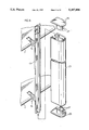
- FIG. 8 is an enlarged partially exploded perspective view of a control bar connected to two shutters according to a preferred embodiment of the present invention.
- FIG. 1 shows a louvred shutter generally indicated at 1 and preferably constructed from vinyl or some other similar type of resin material.
- This shutter is formed by an outside frame including styles 3 and opposite end headers 5.
- a centre frame section 6 is also provided extending between the styles 3.
- Each of these louvres includes opposite end pins or axles which are rotationally secured within the styles and allowing pivotal movement of the louvres.
- the louvres are arranged in two groups, one above and one below the centre frame section 6.
- the louvres in each group are moveable in unison with one another by means of a control bar including bar member 11.
- the control bar includes a plurality of connectors generally indicated at 15 as best seen in FIGS. 2 and 3 of the drawings with each connector being secured to one of the individual louvres.
- Each louvre itself as best seen in FIGS. 4 through 6 of the drawings have a hollow construction.
- Each louvre has an opening generally indicated at 9 centrally of its wing-like edge. This opening in combination with the hollow construction provides an undercut recess within the louvre.
- the undercut recess is used for connecting or trapping one of the connector members 15 as will be described later in greater detail.
- Each connector 15 is formed by first and second connector portions 17 and 19. These two portions are molded as a common unit at a generally right angle as shown in FIGS. 6 and 7 of the drawings.
- Connector portion 19 includes a cut-out region 20 which in combination with a bendable plastic construction of the connector allows bending of connector portion 17 relative to connector portion 19 away from its molded configuration to a configuration where the two connector portions are much more in line with one another as shown in FIG. 4 of the drawings.
- This bending of connector portion 17 moves the overall connector from what will be referred to as a connecting position to an insertion position. When the connector is in the connecting position, it will not fit through the opening to the hollow interior of the louvre.
- connector portion 17 is fittable through the louvre opening as shown in FIGS. 4 and 5 of the drawings.
- the memory of the material causes it to move back to its molded connecting position of FIG. 3. In this position, the span across connector portion 17 is greater than the width across opening 9 which is the reason that connector portion 17 cannot be inserted into the opening without first bending it and which is also the reason that connector portion 17, once fitted through the opening, is trapped inside the louver.
- the overall connector 15 is preferably constructed of polypropylene which has very positive characteristics to enhance operation of the connector.
- polypropylene while being bendable without breaking, has a memory which causes it quickly to return to its molded form. Furthermore, it will take substantial abuse without damage or breaking.
- Another feature of the connector is the provision of small cut away areas or recesses 21 in connector portion 19.
- the provision of recesses 21 eases the force required in order to align or substantially align the two connector portions with one another but does not detract from the memory of the material for returning to its pre-molded configuration.
- control bar itself has a multi-component construction best shown in FIG. 8 of the drawings.
- bar member 13 includes the actual connectors 15. Additionally provided is a sheath or cover 23 which includes an undercut recess 24 for sliding over and securing to bar member 13. The overall assembly is then completed by means of upper and lower end caps 25, each of which includes tabs 27 frictionally engaged within sheath 23.
Landscapes
- Engineering & Computer Science (AREA)
- Civil Engineering (AREA)
- Structural Engineering (AREA)
- Connection Of Plates (AREA)
Abstract
Description
Claims (4)
Priority Applications (1)
| Application Number | Priority Date | Filing Date | Title |
|---|---|---|---|
| US07/859,652 US5187896A (en) | 1992-03-30 | 1992-03-30 | Pivot rod connector for moveable shutters |
Applications Claiming Priority (1)
| Application Number | Priority Date | Filing Date | Title |
|---|---|---|---|
| US07/859,652 US5187896A (en) | 1992-03-30 | 1992-03-30 | Pivot rod connector for moveable shutters |
Publications (1)
| Publication Number | Publication Date |
|---|---|
| US5187896A true US5187896A (en) | 1993-02-23 |
Family
ID=25331421
Family Applications (1)
| Application Number | Title | Priority Date | Filing Date |
|---|---|---|---|
| US07/859,652 Expired - Lifetime US5187896A (en) | 1992-03-30 | 1992-03-30 | Pivot rod connector for moveable shutters |
Country Status (1)
| Country | Link |
|---|---|
| US (1) | US5187896A (en) |
Cited By (24)
| Publication number | Priority date | Publication date | Assignee | Title |
|---|---|---|---|---|
| US5303507A (en) * | 1992-11-02 | 1994-04-19 | Fashion Fold Products Inc | Adjustable shutters and slats therefor |
| US5392561A (en) * | 1992-01-13 | 1995-02-28 | Henley, Sr.; John B. | Shutter assembly system with individually removable components |
| USD362059S (en) | 1994-03-18 | 1995-09-05 | William Wojcik | Register cover |
| US5469658A (en) * | 1992-03-20 | 1995-11-28 | Digianni; Michele | Louvre shutter device with variable slats |
| US5548925A (en) * | 1995-06-14 | 1996-08-27 | Marocco; Norbert | Toggle connector for shutter control bar |
| US5595231A (en) * | 1994-11-10 | 1997-01-21 | Marocco; Norbert | Suspended shutter |
| US5778598A (en) * | 1992-10-27 | 1998-07-14 | U.S. Polymers, Inc. | Shutter door assembly |
| US5887386A (en) * | 1998-04-28 | 1999-03-30 | Timeless Shutters Incorporated | Window shutters with movable louvers |
| US6014839A (en) * | 1997-12-05 | 2000-01-18 | Bryan Ruggles | Electronic actuator for architectural shutters |
| US6250012B1 (en) * | 1997-11-28 | 2001-06-26 | Ricci Tools Inc. | Louver assembly with multi-position louver adjusting control rod having clamping connecting arms |
| US6266923B1 (en) * | 1999-06-11 | 2001-07-31 | Han-Sen Lee | Shutter system and pivoting connectors |
| US6418665B1 (en) * | 2001-06-14 | 2002-07-16 | Vinylbilt Shutter Systems Inc. | Louver control bar with bendable louver attachment members |
| GB2374376A (en) * | 2001-04-11 | 2002-10-16 | Levolux At Ltd | A louvre system |
| US6510655B1 (en) * | 2000-10-11 | 2003-01-28 | Emilio Antonini | Device to move blinds or jalousies |
| US20040025438A1 (en) * | 2002-08-08 | 2004-02-12 | Shade-O-Matic Limited | Pull bar connector for shutters |
| US6732475B1 (en) | 2000-04-03 | 2004-05-11 | Han-Sen Lee | User customizable shutter system |
| US6761203B1 (en) | 2003-03-31 | 2004-07-13 | Tai-Long Huang | Balanced window blind having a spring motor for concealed pull cords thereof |
| US20040168368A1 (en) * | 2003-02-28 | 2004-09-02 | Chen Chang Than | Shutter assembly for being easily assembled |
| US20090119999A1 (en) * | 2007-11-14 | 2009-05-14 | Maxxmar Inc | Toggle bar and shutter |
| US20090120000A1 (en) * | 2007-11-14 | 2009-05-14 | Maxxmar Inc | Shutter with multi-part tilt control bar connector |
| US20090126277A1 (en) * | 2007-11-21 | 2009-05-21 | Maxxmar Inc | Plug in pull bar hinge |
| US20100088960A1 (en) * | 2008-10-14 | 2010-04-15 | Levolux A T Limited | Solar-shading assembly with hidden fastening device |
| US20120082508A1 (en) * | 2010-02-26 | 2012-04-05 | Michael Cerillo | Shutter Repair System |
| US8375634B2 (en) * | 2010-08-19 | 2013-02-19 | Ari Meyer Brandley | Modular shutter system for poultry house ventilation and insulation |
Citations (8)
| Publication number | Priority date | Publication date | Assignee | Title |
|---|---|---|---|---|
| US395902A (en) * | 1889-01-08 | iieidt | ||
| US456306A (en) * | 1891-07-21 | heidt | ||
| US1340252A (en) * | 1919-09-05 | 1920-05-18 | Niels C Rasmussen | Blind-slat attachment |
| US2761185A (en) * | 1955-10-24 | 1956-09-04 | Glenn L Sherwood | Blind or like slat or louver assembly and method of assembling |
| NL6501514A (en) * | 1964-02-10 | 1965-08-11 | ||
| US4655003A (en) * | 1986-04-16 | 1987-04-07 | Henley Sr John B | Shutter assembly with individually removable slats |
| US4996793A (en) * | 1990-07-05 | 1991-03-05 | Aaa Sales & Engineering, Inc. | Louver control apparatus for modular shutter assembly |
| US5001864A (en) * | 1988-10-28 | 1991-03-26 | Truscott Robert D | Shutter assemblies |
-
1992
- 1992-03-30 US US07/859,652 patent/US5187896A/en not_active Expired - Lifetime
Patent Citations (8)
| Publication number | Priority date | Publication date | Assignee | Title |
|---|---|---|---|---|
| US395902A (en) * | 1889-01-08 | iieidt | ||
| US456306A (en) * | 1891-07-21 | heidt | ||
| US1340252A (en) * | 1919-09-05 | 1920-05-18 | Niels C Rasmussen | Blind-slat attachment |
| US2761185A (en) * | 1955-10-24 | 1956-09-04 | Glenn L Sherwood | Blind or like slat or louver assembly and method of assembling |
| NL6501514A (en) * | 1964-02-10 | 1965-08-11 | ||
| US4655003A (en) * | 1986-04-16 | 1987-04-07 | Henley Sr John B | Shutter assembly with individually removable slats |
| US5001864A (en) * | 1988-10-28 | 1991-03-26 | Truscott Robert D | Shutter assemblies |
| US4996793A (en) * | 1990-07-05 | 1991-03-05 | Aaa Sales & Engineering, Inc. | Louver control apparatus for modular shutter assembly |
Cited By (37)
| Publication number | Priority date | Publication date | Assignee | Title |
|---|---|---|---|---|
| US5392561A (en) * | 1992-01-13 | 1995-02-28 | Henley, Sr.; John B. | Shutter assembly system with individually removable components |
| US5469658A (en) * | 1992-03-20 | 1995-11-28 | Digianni; Michele | Louvre shutter device with variable slats |
| US5778598A (en) * | 1992-10-27 | 1998-07-14 | U.S. Polymers, Inc. | Shutter door assembly |
| US5303507A (en) * | 1992-11-02 | 1994-04-19 | Fashion Fold Products Inc | Adjustable shutters and slats therefor |
| USD362059S (en) | 1994-03-18 | 1995-09-05 | William Wojcik | Register cover |
| US5595231A (en) * | 1994-11-10 | 1997-01-21 | Marocco; Norbert | Suspended shutter |
| US5548925A (en) * | 1995-06-14 | 1996-08-27 | Marocco; Norbert | Toggle connector for shutter control bar |
| US6250012B1 (en) * | 1997-11-28 | 2001-06-26 | Ricci Tools Inc. | Louver assembly with multi-position louver adjusting control rod having clamping connecting arms |
| US6014839A (en) * | 1997-12-05 | 2000-01-18 | Bryan Ruggles | Electronic actuator for architectural shutters |
| US5887386A (en) * | 1998-04-28 | 1999-03-30 | Timeless Shutters Incorporated | Window shutters with movable louvers |
| US6602014B2 (en) | 1999-06-11 | 2003-08-05 | Han-Sen Lee | Shutter system and pivoting connectors |
| US6266923B1 (en) * | 1999-06-11 | 2001-07-31 | Han-Sen Lee | Shutter system and pivoting connectors |
| US6732475B1 (en) | 2000-04-03 | 2004-05-11 | Han-Sen Lee | User customizable shutter system |
| US6510655B1 (en) * | 2000-10-11 | 2003-01-28 | Emilio Antonini | Device to move blinds or jalousies |
| AU783383B2 (en) * | 2000-10-11 | 2005-10-20 | Emilio Antonini | Device to move blinds or jalousies |
| GB2374376A (en) * | 2001-04-11 | 2002-10-16 | Levolux At Ltd | A louvre system |
| GB2374376B (en) * | 2001-04-11 | 2004-04-28 | Levolux At Ltd | A louvre system |
| WO2002103147A1 (en) * | 2001-06-14 | 2002-12-27 | Vinylbilt Shutter Systems Inc. | Louver control bar with bendable louver attachment members |
| US6418665B1 (en) * | 2001-06-14 | 2002-07-16 | Vinylbilt Shutter Systems Inc. | Louver control bar with bendable louver attachment members |
| AU2002311121B2 (en) * | 2001-06-14 | 2007-11-15 | Vinylbilt Shutter Systems Inc. | Louver control bar with bendable louver attachment members |
| US20040025438A1 (en) * | 2002-08-08 | 2004-02-12 | Shade-O-Matic Limited | Pull bar connector for shutters |
| US7377074B2 (en) * | 2002-08-08 | 2008-05-27 | Norbert Marocco | Pull bar connector for shutters |
| US20040168368A1 (en) * | 2003-02-28 | 2004-09-02 | Chen Chang Than | Shutter assembly for being easily assembled |
| US6817141B2 (en) * | 2003-02-28 | 2004-11-16 | Chang Than Chen | Shutter assembly for being easily assembled |
| US6761203B1 (en) | 2003-03-31 | 2004-07-13 | Tai-Long Huang | Balanced window blind having a spring motor for concealed pull cords thereof |
| US20090119999A1 (en) * | 2007-11-14 | 2009-05-14 | Maxxmar Inc | Toggle bar and shutter |
| US20090120000A1 (en) * | 2007-11-14 | 2009-05-14 | Maxxmar Inc | Shutter with multi-part tilt control bar connector |
| US7578093B2 (en) * | 2007-11-14 | 2009-08-25 | Mario M Marocco | Shutter with multi-part tilt control bar connector |
| US7607261B2 (en) * | 2007-11-14 | 2009-10-27 | Mario M Marocco | Toggle bar and shutter |
| US20090126277A1 (en) * | 2007-11-21 | 2009-05-21 | Maxxmar Inc | Plug in pull bar hinge |
| US7603810B2 (en) * | 2007-11-21 | 2009-10-20 | Mario M Marocco | Plug in pull bar hinge |
| US20100088960A1 (en) * | 2008-10-14 | 2010-04-15 | Levolux A T Limited | Solar-shading assembly with hidden fastening device |
| US8256167B2 (en) * | 2008-10-14 | 2012-09-04 | Levolux A T Limited | Solar-shading assembly with hidden fastening device |
| GB2500838A (en) * | 2008-10-14 | 2013-10-02 | Levolux At Ltd | Solar-shading assembly with hidden fastening device |
| GB2500838B (en) * | 2008-10-14 | 2013-12-25 | Levolux At Ltd | Solar-Shading Assembly With Hidden Fastener |
| US20120082508A1 (en) * | 2010-02-26 | 2012-04-05 | Michael Cerillo | Shutter Repair System |
| US8375634B2 (en) * | 2010-08-19 | 2013-02-19 | Ari Meyer Brandley | Modular shutter system for poultry house ventilation and insulation |
Similar Documents
| Publication | Publication Date | Title |
|---|---|---|
| US5187896A (en) | Pivot rod connector for moveable shutters | |
| US6401391B2 (en) | Louver control in a movable louver assembly | |
| US5152116A (en) | Modular shutter assembly | |
| US6301843B1 (en) | Muntin joint | |
| CA2436460C (en) | Pull bar connector for shutters | |
| DE4338762C2 (en) | Push button switch | |
| US5548925A (en) | Toggle connector for shutter control bar | |
| US6874200B2 (en) | Hinge and hinge part therefor | |
| DE4129938A1 (en) | PUSH BUTTON SWITCH | |
| CA2500148C (en) | Flush mounted louver end cap with tolerance flashing | |
| DE10324521A1 (en) | fuse | |
| CA2063963C (en) | Louvre control connector | |
| US20050103451A1 (en) | Bottom rail for window blind | |
| CA2205164A1 (en) | Door frame | |
| CA2350537C (en) | Louver control bar with bendable louver attachment members | |
| CA2629662C (en) | Plug in pull bar hinge | |
| DE8034127U1 (en) | Two-part housing | |
| EP2281159B1 (en) | Door for a household appliance | |
| KR200270291Y1 (en) | Opening and closing device of shutter for ventilation window | |
| CA2224834C (en) | Louver control in a movable louver assembly | |
| US6530179B1 (en) | Continuous extruded frame and movable panel with continuous inextruded hinge extruded within | |
| AU2002311121A1 (en) | Louver control bar with bendable louver attachment members | |
| KR100376971B1 (en) | sliding system of fly net window | |
| US20070193188A1 (en) | Muntin Clip | |
| CA2226066C (en) | Plastic louver body and end cap assembly |
Legal Events
| Date | Code | Title | Description |
|---|---|---|---|
| AS | Assignment |
Owner name: DOMINION PLASTICS INC. Free format text: ASSIGNMENT OF ASSIGNORS INTEREST.;ASSIGNOR:ROSS, ALAN;REEL/FRAME:006070/0282 Effective date: 19920309 |
|
| STCF | Information on status: patent grant |
Free format text: PATENTED CASE |
|
| FEPP | Fee payment procedure |
Free format text: PAT HLDR NO LONGER CLAIMS SMALL ENT STAT AS SMALL BUSINESS (ORIGINAL EVENT CODE: LSM2); ENTITY STATUS OF PATENT OWNER: LARGE ENTITY |
|
| REMI | Maintenance fee reminder mailed | ||
| FPAY | Fee payment |
Year of fee payment: 4 |
|
| SULP | Surcharge for late payment | ||
| FPAY | Fee payment |
Year of fee payment: 8 |
|
| FPAY | Fee payment |
Year of fee payment: 12 |
|
| AS | Assignment |
Owner name: ROYAL GROUP TECHNOLOGIES INC., CANADA Free format text: MERGER;ASSIGNOR:DOMINION PLASTICS INC.;REEL/FRAME:018303/0649 Effective date: 20020930 |
|
| AS | Assignment |
Owner name: 4385853 CANADA INC., CANADA Free format text: CHANGE OF NAME;ASSIGNOR:ROYAL GROUP TECHNOLOGIES INC.;REEL/FRAME:023607/0426 Effective date: 20060922 |
|
| AS | Assignment |
Owner name: ROYAL GROUP TECHNOLOGIES LIMITED, CANADA Free format text: MERGER;ASSIGNOR:4385853 CANADA INC.;REEL/FRAME:023607/0859 Effective date: 20060927 Owner name: ROYAL GROUP, INC., GEORGIA Free format text: CHANGE OF NAME;ASSIGNOR:ROYAL GROUP TECHNOLOGIES LIMITED;REEL/FRAME:023607/0985 Effective date: 20070201 |