US517734A - X x x x x - Google Patents
X x x x x Download PDFInfo
- Publication number
- US517734A US517734A US517734DA US517734A US 517734 A US517734 A US 517734A US 517734D A US517734D A US 517734DA US 517734 A US517734 A US 517734A
- Authority
- US
- United States
- Prior art keywords
- ore
- belt
- nozzle
- velocity
- chute
- Prior art date
- Legal status (The legal status is an assumption and is not a legal conclusion. Google has not performed a legal analysis and makes no representation as to the accuracy of the status listed.)
- Expired - Lifetime
Links
- 230000033001 locomotion Effects 0.000 description 8
- 230000035611 feeding Effects 0.000 description 3
- 239000006148 magnetic separator Substances 0.000 description 3
- XEEYBQQBJWHFJM-UHFFFAOYSA-N Iron Chemical compound [Fe] XEEYBQQBJWHFJM-UHFFFAOYSA-N 0.000 description 2
- 239000002245 particle Substances 0.000 description 2
- 230000003247 decreasing effect Effects 0.000 description 1
- 230000003292 diminished effect Effects 0.000 description 1
- 238000007599 discharging Methods 0.000 description 1
- 230000005484 gravity Effects 0.000 description 1
- 229910052742 iron Inorganic materials 0.000 description 1
- 238000007885 magnetic separation Methods 0.000 description 1
- 230000001105 regulatory effect Effects 0.000 description 1
Images
Classifications
-
- B—PERFORMING OPERATIONS; TRANSPORTING
- B03—SEPARATION OF SOLID MATERIALS USING LIQUIDS OR USING PNEUMATIC TABLES OR JIGS; MAGNETIC OR ELECTROSTATIC SEPARATION OF SOLID MATERIALS FROM SOLID MATERIALS OR FLUIDS; SEPARATION BY HIGH-VOLTAGE ELECTRIC FIELDS
- B03C—MAGNETIC OR ELECTROSTATIC SEPARATION OF SOLID MATERIALS FROM SOLID MATERIALS OR FLUIDS; SEPARATION BY HIGH-VOLTAGE ELECTRIC FIELDS
- B03C1/00—Magnetic separation
- B03C1/02—Magnetic separation acting directly on the substance being separated
- B03C1/10—Magnetic separation acting directly on the substance being separated with cylindrical material carriers
Definitions
- the part of'the magnetic separator shown v so sufficient height to enable the crnshed ore in in consider, is the carrying belt A which is intended to be moved with great velocity in the direction of arrow 1 for the purpose of carrying through the magnetic field of the apparatusa thinly spread mass of crushed ore.
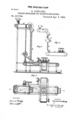
- the devices for properly delivering the crushed ore embrace the curved nozzle 0 which is a flattened tube curved substantially as shown, so as to deliver its contents in a plane parallel with and-in close proximity to the surface of the carrying belt A.
- the nozzle 0 is connected to the lower end of the upright feed chute B; the upper end ol-which is provided with a daring mouth B into which the crushed ore isfed by any suitable means as for example by the slow moving feed belt E upon which a layer of crushed ore of considerable thickness is deposited from the hopper F.
- a blower D may if desired, be connected with the feed chute B,thefspout E of the blower being inline with the nozzle 6 as shown in Fig.
- the ore is dropped may be elevated above the nozzle, to a height which is more than suilicient to enable the falling ore to acquire the desired velocity.
- the stream of ore delivered from the elevated feed belt E will in this case fall through the short tube E into the adjustable inclined trough G from the lower end of which it will be discharged into that veloci y, Conne -fly; f it be desired to increase the velocity with which the oreis.
- the trough Gg will be tilted into a more steeply incliriedp'osb' tion, in which case the crushed ore willenter the feedchute B with a greaterivelocity'cfl motion.
- the speed of movement with which the-crushed ore isde'livered from the nozzle G resu1ts in part from the a velocity i acquires in falling through-the ehuteB and in part from he velocity it sesses priorftoi'ts entrance into. said chute,
- adjustableinclined trough ,G afiords aconvenient means of ,efifectively varying the velocity with which urret iver d fr he zzl 0 as m be required in order to make'that velocity substantially the same as thelvelocity otthe' carrying belt A.
Landscapes
- Manufacture And Refinement Of Metals (AREA)
Description
v '3 AVAILABLE 630W (No Model.)
* G. CO NKLINGM FEEDING MECHANISM FOR MAGNETIC SEPABATORS .N0.-517 ,734. '7 I atenped n-a 1-894.
, W/TNESSES w MWZM ATTORNEY i5 following specification and claims, and. illnsv accompanying drawings, in
belt or a magnetic separator.
, l This invention 1 c 'UNITED STATES,-
i ennnon ooNKLnve, or, GLENs'FALLs, NEWYORK.
Planning hdCHA-NISM FOR MAGN we sEPARAToRs] I srncl-mcnrzolvrbrmin grt 0f Letters Patent 5173a, Medias a, 1394.
' Ap ninm firearm 2.5, 1:891.
1'6 ail whom it may c'oa cemi' "-Be itknown thatLGURDONOONKLING, a citizen'ot the United Statesresidingat Glens; Falls, in the countyol? Warren andState of' New York, have invented new and useful Improvements in Feeding Mechanism for Mag- .netic Separatorspof which the followingis' a specification bm thatclass of. devices known as magneticore separators, and more particnlarlyto the feed ing, mechanism thereof,wherein' the massflto be separated is fed upon a'beltfor cc'n'veyer which carries it through the magnetic field,-
said improvements being pointed cut in" the trated in the Figure I. represents-a vertical section of 'a magnetic separator of the type of that described in Letterslatent No. 383,868, granted to me June 5,1888. Fig. 2 is a plan or tnp View. Fig. 3 is a symbolicrepresentation of r a'stationary hopper discharging its contents 5 through a vertical tube of prescribed length into an adjustable inclincdi trough from they lower and oi'which"thecrnshed ore is dis In efiecting the'magnetic separation of'iron particles from dry crushed oreby means of a belt which carries the crushed ore through the magnetic" field, it is desirable that the crushed ore be thinly spread upon 'said beltf idly moving feed belt, of at delivering device embracing means for imparting to a thin WTnETWRM stream or sheet of crushed ore a velocity of motion approximately in the direction of movementiof the belt which is the same or satin No. 397,446. (1a tt);
relates to improvement-sin,
nearly the same as thevelocity of the belt, Under such conditions of delivery there will be no throwing oil of the particles of crushed ore from' the belt and no vibratory motions imparted to the belt tendingjto'tossthe ore lying upon its surface, as therewonld be it 'belt anda velocity of motion approximately to thatof the belt. Furthermore, the stream of 'crnshedere before it reaches the belt, is' spread so that-the ore when delivered npon thebelt forms a thin layer of apprcximately uniform depth.
It willreadily-b'e perceived that there are" a variety of waysin which the desired motion can'be'imparted to the crushed ore. It essential that the flattened nozzle from which the'crushed ore isdischarged shall terminate in a plane parallel. with and near the surface of the belt. The crushed ore be fed into a chute with which such nozzle connects and. may be driven out of the neziale by a Gillrent of'air of the required velocity furnished by a suitableblower. It will usually be pre ferred, however, to connect the nozzle with the lower end or avertical chute or flattened tube, into the flaring upper end'or mouth of which the crushed ore isfed and which is 'of ,velocity with which-the crushed ore is de-1 livered, when. gravity is relied upon to give it its motion, may if desired,'-be. elfectively 1 regulated by making the instrumentality,
which supplies ore to thechute vertically ad justable or by delivering the crushed one into the flaring mouth" of the feed'chutefrom an inclined trough, into the upper part of which thecrushed ore is fed from a prescribed elevation and by means ofi which the speed of motion cf the crushed oreatthe instant of its delivery into the feed chute, may be varied The part of'the magnetic separator shown v so sufficient height to enable the crnshed ore in in consider, is the carrying belt A which is intended to be moved with great velocity in the direction of arrow 1 for the purpose of carrying through the magnetic field of the apparatusa thinly spread mass of crushed ore.
The devices for properly delivering the crushed ore embrace the curved nozzle 0 which is a flattened tube curved substantially as shown, so as to deliver its contents in a plane parallel with and-in close proximity to the surface of the carrying belt A. The nozzle 0 is connected to the lower end of the upright feed chute B; the upper end ol-which is provided with a daring mouth B into which the crushed ore isfed by any suitable means as for example by the slow moving feed belt E upon which a layer of crushed ore of considerable thickness is deposited from the hopper F. A blower D may if desired, be connected with the feed chute B,thefspout E of the blower being inline with the nozzle 6 as shown in Fig. 1 for the purpose of forcing a currentcot' air through the nozzle with such direction and such force as to drive the crushed ore out of the nozzle with the desired velocity. It will not be necessary to employ a blower when the conditions under which the apparatus is to be used, are such that the feed chute B may be .made of such ascertained height that, the falling masso'f crushed ore will have time to acquirethe de-,'
gree of velocity necessary to enable it to, issue from the nozzle with the same, or nearly the, same, speed as, that of the belt. 7 example, if the height of the Y surface of the slow moving belt- E, from which thejore falls be f ur feetahev the e n zl ith fal ing ore will have acquired a velocity of sixteen feet per secondfbefore it strikes the curve of the nozzle. Assuming thatits Ye,-
locit'yis so'far diminished by impact with the curved nozzle as tore'duce it to a speed'of say" eight feet per second, it'will then issue from the nozzle with a velocity the same as that of a carryingbelt traveling at the rate of four hundred and eighty feet per minute, which is an entirely practicable speed for this belt. By'impact witlrthe curved nozzle the mass of ore descending through the feed chute B will be spread and delivered upon the carrying belt in a uniform layer, the thickness of v which can be controlled by increasing or decreasing the speed of the feed belt E, or the quantity of crushed ore. dropped into the flaring mouth B of the chute B; By increasing theheight of the feed chute, the speed at which the crushed ore is delivered from the nozzle will be increased and vice versa, and the speed of the carrying beltmust be changed accordingly; If it is desired from time to time to vary the velocity with which the crushed ore is delivered, an expedient similar to that symbolically represented in Fig. 3, may be employed. Thus a slow moving, belt E or other instrumentality from which Thus, for,
the ore is dropped, may be elevated above the nozzle, to a height which is more than suilicient to enable the falling ore to acquire the desired velocity. The stream of ore delivered from the elevated feed belt E will in this case fall through the short tube E into the adjustable inclined trough G from the lower end of which it will be discharged into that veloci y, Conne -fly; f it be desired to increase the velocity with which the oreis.
delivered from the. nozzle 0, the trough Ggwill be tilted into a more steeply incliriedp'osb' tion, in which case the crushed ore willenter the feedchute B with a greaterivelocity'cfl motion. inasmuch as, the speed of movement with which the-crushed ore isde'livered from the nozzle G,resu1ts in part from the a velocity i acquires in falling through-the ehuteB and in part from he velocity it sesses priorftoi'ts entrance into. said chute,
it will be perceived that the adjustableinclined trough ,G afiords aconvenient means of ,efifectively varying the velocity with which urret iver d fr he zzl 0 as m be required in order to make'that velocity substantially the same as thelvelocity otthe' carrying belt A.
.1 What I claim as new, and desire measure by Letters Patent, isr '15 In combination with a magnetic ore separator comprising the rapidly and slowly moving belts, one mounted above the o,ther,mechanismjsubst-antially s described foroperating said belts, of a chute conveyingore'froin one'belt to the other, and a fan blower conneeted to and adapted to deliver a current of air into said chute whereby the velocity of the ore is increased, substantially as described.
2. The combination with, an ore separator provided with rapidly and slowly moving belts one mounted above theother, of a chute B, having a bent nozzle G 31; its delivery end,
and a fan blower D, providedwith an inclined spout E said spout being connected tothe chute in a line'with the nozzle 0, whereby the air from the fan is directed in the nozzle,v substantially as and for the purpose set forth,
' 3. In an ore separator, the combination with the belts A, E, one mounted above the other, mechanism, substantially as described, for driving said belts, of a vertical chute B. intermediate. of the belts and adapted. to deliver ore from one to the 0th,e r, a bout 'ozzlc C on the dischargeend of they chute, the bend i of which is in the direction of the travel of IOC the belt, an air-blast connected to the chute In testimony whereof I have hereunto set 1 v in a. line substantially straight with that of my hand in the presence of two subscribing the delivery end thereof, and a connection witnesses.
GURDON OONKLING.
with the mechanism driving the belt with 5 that of the air-blast whereby the latteris Witnesses:
driven therefrom, substantially as and for WM. CJHAUFF, the purpose set forth. 7 E. FQKASTENHUBER.
Publications (1)
| Publication Number | Publication Date |
|---|---|
| US517734A true US517734A (en) | 1894-04-03 |
Family
ID=2586537
Family Applications (1)
| Application Number | Title | Priority Date | Filing Date |
|---|---|---|---|
| US517734D Expired - Lifetime US517734A (en) | X x x x x |
Country Status (1)
| Country | Link |
|---|---|
| US (1) | US517734A (en) |
Cited By (1)
| Publication number | Priority date | Publication date | Assignee | Title |
|---|---|---|---|---|
| DE765781C (en) * | 1940-08-16 | 1954-02-22 | Koppers Gmbh Heinrich | Process for the dry separation of magnetic substances |
-
0
- US US517734D patent/US517734A/en not_active Expired - Lifetime
Cited By (1)
| Publication number | Priority date | Publication date | Assignee | Title |
|---|---|---|---|---|
| DE765781C (en) * | 1940-08-16 | 1954-02-22 | Koppers Gmbh Heinrich | Process for the dry separation of magnetic substances |
Similar Documents
| Publication | Publication Date | Title |
|---|---|---|
| US3012651A (en) | Apparatus for orienting and feeding articles | |
| US4191294A (en) | Empty capsule ejector | |
| CN103702799B (en) | Shot-blast equipment | |
| US4851110A (en) | Air pump separator method and apparatus | |
| FI76714B (en) | LUFTSTROEMSSEPARATOR. | |
| CN105855040B (en) | A kind of inclined is classified concentration equipment | |
| US517734A (en) | X x x x x | |
| US5080235A (en) | Small particle separator | |
| US4365717A (en) | Feed apparatus and method | |
| CN104379318B (en) | Device and method for conveying preforms | |
| US2164676A (en) | Vibratory chute | |
| CN112495833A (en) | Mineral product sorting machine | |
| US1196048A (en) | Eewjt h | |
| US675057A (en) | Apparatus for screening pulverized material. | |
| JP4667015B2 (en) | Wind sorter | |
| US239994A (en) | Tereitoby | |
| US539325A (en) | Cotton elevator and distributer | |
| US739231A (en) | Gold-separator. | |
| US2302532A (en) | Separation of bodies of different physical properties | |
| US550911A (en) | John corey fell | |
| US704010A (en) | Apparatus for concentrating magnetic iron ores. | |
| US207878A (en) | Improvement in ore-separators | |
| US539296A (en) | piette | |
| US753592A (en) | Separator | |
| US272178A (en) | Grain-separator |