US5169203A - Vehicle sun visor catch - Google Patents
Vehicle sun visor catch Download PDFInfo
- Publication number
- US5169203A US5169203A US07/844,981 US84498192A US5169203A US 5169203 A US5169203 A US 5169203A US 84498192 A US84498192 A US 84498192A US 5169203 A US5169203 A US 5169203A
- Authority
- US
- United States
- Prior art keywords
- pin
- visor
- catch
- core
- support
- Prior art date
- Legal status (The legal status is an assumption and is not a legal conclusion. Google has not performed a legal analysis and makes no representation as to the accuracy of the status listed.)
- Expired - Fee Related
Links
Images


Classifications
-
- B—PERFORMING OPERATIONS; TRANSPORTING
- B60—VEHICLES IN GENERAL
- B60J—WINDOWS, WINDSCREENS, NON-FIXED ROOFS, DOORS, OR SIMILAR DEVICES FOR VEHICLES; REMOVABLE EXTERNAL PROTECTIVE COVERINGS SPECIALLY ADAPTED FOR VEHICLES
- B60J3/00—Antiglare equipment associated with windows or windscreens; Sun visors for vehicles
- B60J3/02—Antiglare equipment associated with windows or windscreens; Sun visors for vehicles adjustable in position
- B60J3/0204—Sun visors
- B60J3/0213—Sun visors characterised by the mounting means
- B60J3/023—Additional support bracket releasably holding the sun visor
Definitions
- This invention relates generally to sun visors for use in motor vehicles, and more particularly to a catch for the engagement of a sun visor with, and disengagement from, a center mounting bracket in a vehicle.
- Motor vehicle sun visors typically include a pivot arm by which the visor is pivotally attached to an outer (with respect to the center line of the vehicle's interior) mounting bracket, and a catch by which the visor may be removably secured to a center mounting bracket.
- the pivot arm allows the visor to pivot downwardly from a stowed position against the vehicle headliner to a lowered, use position against the windshield.
- the visor can be disengaged from the center bracket, and the visor can be rotated with the pivot arm to cover a side window if the sun is entering the vehicle from the side.
- the visor When the visor is no longer needed, it can be rotated back to a stored position, and reattached to the center bracket by the catch.
- Such a catch must provide positive visor retention to the center bracket for storage of the visor against the headliner, and for use of the visor in the lowered position.
- the catch must provide easy disengagement of the visor from the center bracket for positioning the visor against the vehicle side window, and easy reengagement with the bracket for return to the stored position.
- One known means of achieving such ease of engagement and disengagement is to provide the catch with a freely rotatable, cylindrical sleeve at the upper edge of the visor, the sleeve being supported along its center axis by a fixed shaft.
- the sleeve is freely rotatable about the shaft, whereby the sleeve acts as a roller bearing, requiring minimal force to engage with, and disengage from, a clip on the center bracket.
- Sun visors employing this catch configuration require less effort to engage with and disengage from the mounting bracket than is required with other catches, and therefore, minimizes operator distraction during normal use of the visor.
- Prior art catches which employ such a cylindrical sleeve and shaft arrangement are generally incompatible with known assembly techniques for current high quality sun visors of refined appearance.
- sun visors typically comprise a rigid core covered with upholstery material aesthetically compatible with various vehicle interior fabrics.
- the catch is usually assembled to the core prior to covering and, unless particularly adapted to the visor in which it is used, can contribute significantly to the cost of assembling the visor.
- Objects of the invention include the provision of an improved sun visor catch which is conveniently assembled to a vehicle sun visor.
- a cylindrical roller sleeve is received over a pin, each end of which is retained by a support in a first, single portion of a visor core. Longitudinal movement of the pin is prevented by an edge of the visor core adjacent to one of the supports, and a stop adjacent to the other support. A pair of tabs on an opposed visor portion holds the pin securely in the supports when the core portions are bonded together to prevent lateral disengagement of the pin from the supports.
- the sleeve may freely rotate about the axis of the pin.
- the present invention represents an improvement over previous visor catches because it exhibits the superior mechanical qualities of being easy to engage with, and disengage from, a center mounting bracket, while being particularly well suited for use in a refined, aesthetically pleasing visor.
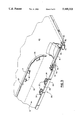
- FIG. 1 is a perspective view of a vehicle interior having a sun visor employing the catch of the present invention, disengaged from a center mounting bracket.
- FIG. 2 is a perspective view of the visor shown in FIG. 1 in a state of partial assembly, portions thereof having been broken away to show details of construction.
- FIG. 3 is an enlarged perspective view of a core employed in the visor of FIG. 1, a flap in the core being shown open.
- FIG. 4 is an enlarged perspective view of the catch of the present invention.
- the interior 5 of a vehicle such as an automobile or the like, is shown in phantom and includes a sun visor 6, mounted on a pivot arm 7.
- arm 7 is pivotally mounted to a bracket 8 whereby the visor 6 is horizontally pivotable between positions adjacent to a vehicle windshield 9 and a side window 10.
- An upper (forward) edge 11of the visor 6 contains a catch 12 which is engageable with a clip 13 mounted on a center bracket 14 located near the center of the vehicle for latching the visor in a position adjacent to the windshield 9 or, by rotating the visor upwardly on the pivot arm 7, in a stowage position against the vehicle headliner 15.
- a first visor core portion (half) 20 is molded of a suitable material such as polypropylene, with an integral flap21 pivotable about an integral hinge (living hinge) 22 parallel to the forward edge 11.
- a second visor core portion (half) 23 is bonded to the first visor core half 20, except for the flap 21, by a suitable adhesion process such as hot-plate fusion. Flap 21 is left open for assembly of catch 12 with the visor core.
- the bonded core halves 20, 23 form a visor core assembly 30.
- the area between the flap 21 and the second visor core half 23 defines a cavity 31.
- a plurality of snap fasteners are located in the cavity 31 to secure the flap 21 to the second visor core half 23.
- Each of the snap fasteners comprises a resilient L-shaped dog 32, the ends of which snap-fit into theslotted portion of a resilient slotted plate 33, the ends of the dogs beingheld securely in the slots by resilient wedge-shaped locking tabs 34 when the flap is closed against the forward edge 11 of the second visor core half 23.
- a decorative fabric cover (envelope) 35 which is usually color coordinated with fabrics used elsewhere in the interior of the vehicle, isprovided in the shape of the assembly 30. Skirts 36 define an opening in the envelope 35 for insertion of the core assembly thereinto.
- the catch 12 of the present invention consists of a pin 40 received in a cylindrical roller sleeve 41.
- One end of the pin40 is received in the grooved portion of a first support (resilient cradle)42 integrally molded into the second visor core half 23 by a snap fit, and securely held therein by a first tab 43 integrally molded into the first visor core half 20.
- An end of the pin 45 contacts a seam 46 defined by themating edges of the first and second core halves and is longitudinally restrained thereby.
- the other end of the pin 40 is snapped into a second support (resilient cradle) 50 integrally molded into the second visor corehalf 23.
- a second tab 51 integrally molded into the second visor core half 23 adjacent to the second cradle 50 prevents outwardly longitudinal movement of the pin.
- the catch of the present invention is assembled with the visor core assembly 30 and the envelope 35 as follows. As shown in FIG. 2, the core assembly 30 is inserted into the interior of the envelope 35 through the skirts 36. The skirts 36 are folded over the flap 21 and the upper edge ofthe second visor core half 23 into the cavity 31, and attached thereto along interior edges 57, 58 by adhesive or equivalent technique.
- This assembly process is the subject of U.S. Pat. No. 4,998,767 entitled "Vehicle Sun Visor and Method of Making".
- the pin 40 is inserted in the roller sleeve 41, and the ends of the pin are snapped into the cradles 42, 50.
- the flap 21 is pivoted about the living hinge 22 to securely snap fasten to the second visor core half 23 by means of snap fasteners 32 and 33.
- the cylindrical roller remains sleeve free to rotate about the pin 40.
- the catch of the present invention is easily operated with clip 13 on the center bracket 14. It is easily and conveniently assembled with the visor core described herein. However, the catch may also be used with other suitable visor cores, such as a core molded in one piece with a movable flap along the forward edge 11, or a simple clam shell core, not employinga movable flap.
- the supports 42, 50 and the tabs 43, 51, 55 are shown integrally molded into the visor core. However, there are, of course, other suitable means of mounting these components in accordance with the present invention suchas attachment with rivets, screws, or equivalent fasteners, or by adhesive bonding.
Landscapes
- Engineering & Computer Science (AREA)
- Mechanical Engineering (AREA)
- Vehicle Step Arrangements And Article Storage (AREA)
Abstract
Description
Claims (2)
Priority Applications (1)
| Application Number | Priority Date | Filing Date | Title |
|---|---|---|---|
| US07/844,981 US5169203A (en) | 1989-08-25 | 1992-02-07 | Vehicle sun visor catch |
Applications Claiming Priority (2)
| Application Number | Priority Date | Filing Date | Title |
|---|---|---|---|
| US39858689A | 1989-08-25 | 1989-08-25 | |
| US07/844,981 US5169203A (en) | 1989-08-25 | 1992-02-07 | Vehicle sun visor catch |
Related Parent Applications (1)
| Application Number | Title | Priority Date | Filing Date |
|---|---|---|---|
| US39858689A Continuation | 1989-08-25 | 1989-08-25 |
Publications (1)
| Publication Number | Publication Date |
|---|---|
| US5169203A true US5169203A (en) | 1992-12-08 |
Family
ID=27016290
Family Applications (1)
| Application Number | Title | Priority Date | Filing Date |
|---|---|---|---|
| US07/844,981 Expired - Fee Related US5169203A (en) | 1989-08-25 | 1992-02-07 | Vehicle sun visor catch |
Country Status (1)
| Country | Link |
|---|---|
| US (1) | US5169203A (en) |
Cited By (3)
| Publication number | Priority date | Publication date | Assignee | Title |
|---|---|---|---|---|
| FR2766769A1 (en) * | 1997-08-04 | 1999-02-05 | Rockwell Lvs France | Locking assembly for vehicle sun visor |
| US20050179282A1 (en) * | 2004-02-12 | 2005-08-18 | Wieczorek Joseph P. | Visor nail |
| US11383587B2 (en) * | 2018-10-26 | 2022-07-12 | Kyowa Sangyo Co., Ltd. | Vehicle sun visor |
Citations (6)
| Publication number | Priority date | Publication date | Assignee | Title |
|---|---|---|---|---|
| US4570990A (en) * | 1983-05-02 | 1986-02-18 | Prince Corporation | Visor covering |
| US4576409A (en) * | 1982-12-17 | 1986-03-18 | Gebr. Happich Gmbh | Sun visor with molded stiffening frame |
| US4664435A (en) * | 1983-11-26 | 1987-05-12 | Gebr. Happich Gmbh | Sun visor for vehicles |
| US4679843A (en) * | 1984-12-26 | 1987-07-14 | Prince Corporation | Visor mounting clip |
| JPS63166622A (en) * | 1986-12-27 | 1988-07-09 | Kyowa Sangyo Kk | Sun visor of vehicle |
| EP0275903A2 (en) * | 1987-01-22 | 1988-07-27 | Gebr. Happich GmbH | Sun visor for vehicles |
-
1992
- 1992-02-07 US US07/844,981 patent/US5169203A/en not_active Expired - Fee Related
Patent Citations (6)
| Publication number | Priority date | Publication date | Assignee | Title |
|---|---|---|---|---|
| US4576409A (en) * | 1982-12-17 | 1986-03-18 | Gebr. Happich Gmbh | Sun visor with molded stiffening frame |
| US4570990A (en) * | 1983-05-02 | 1986-02-18 | Prince Corporation | Visor covering |
| US4664435A (en) * | 1983-11-26 | 1987-05-12 | Gebr. Happich Gmbh | Sun visor for vehicles |
| US4679843A (en) * | 1984-12-26 | 1987-07-14 | Prince Corporation | Visor mounting clip |
| JPS63166622A (en) * | 1986-12-27 | 1988-07-09 | Kyowa Sangyo Kk | Sun visor of vehicle |
| EP0275903A2 (en) * | 1987-01-22 | 1988-07-27 | Gebr. Happich GmbH | Sun visor for vehicles |
Cited By (6)
| Publication number | Priority date | Publication date | Assignee | Title |
|---|---|---|---|---|
| FR2766769A1 (en) * | 1997-08-04 | 1999-02-05 | Rockwell Lvs France | Locking assembly for vehicle sun visor |
| US20050179282A1 (en) * | 2004-02-12 | 2005-08-18 | Wieczorek Joseph P. | Visor nail |
| US7025400B2 (en) | 2004-02-12 | 2006-04-11 | Irvin Automotive Products, Inc. | Visor nail |
| US20060123614A1 (en) * | 2004-02-12 | 2006-06-15 | Irvin Automotive Products, Inc. | Visor nail |
| US7204539B2 (en) * | 2004-02-12 | 2007-04-17 | Irvin Automotive Products, Inc. | Visor nail |
| US11383587B2 (en) * | 2018-10-26 | 2022-07-12 | Kyowa Sangyo Co., Ltd. | Vehicle sun visor |
Similar Documents
| Publication | Publication Date | Title |
|---|---|---|
| US4679843A (en) | Visor mounting clip | |
| US5365416A (en) | Sun visor with integral core | |
| US4353593A (en) | Sun visor | |
| US5374097A (en) | Universal visor mounting system | |
| CA1280923C (en) | Sun visor mirror | |
| US5331525A (en) | Low profile sun visor system with remote lighting | |
| US5417466A (en) | Sun visor system | |
| US5871252A (en) | Telescopic sunvisor | |
| US6547308B2 (en) | Visor mounting assembly | |
| US4858982A (en) | Visor | |
| US4958878A (en) | Headliner with integral visor | |
| JPH08207563A (en) | Bearing block piece for sunvisor for automobile | |
| US5333927A (en) | Sun shield for a windshield | |
| JPS5940936A (en) | Shielding visor | |
| US5169203A (en) | Vehicle sun visor catch | |
| US5039153A (en) | Pivot down vanity mirror assembly | |
| US5975708A (en) | Visor with pivoting vanity mirror assembly | |
| US5431473A (en) | Mirror cover and visor extender | |
| US6409246B1 (en) | Snap-in hinged visor extender | |
| JPS61200025A (en) | Tilt and slide type sun roof of car | |
| JPH01254422A (en) | Structure for installing auxiliary visor of automobile | |
| US5921607A (en) | Vehicle sun visor extension | |
| GB2338511A (en) | Member for controlling movement of a vehicle sun visor | |
| US3433525A (en) | Vehicle sunshade fastening means | |
| JP2002012028A (en) | Sunvisor for vehicle |
Legal Events
| Date | Code | Title | Description |
|---|---|---|---|
| FEPP | Fee payment procedure |
Free format text: PAYOR NUMBER ASSIGNED (ORIGINAL EVENT CODE: ASPN); ENTITY STATUS OF PATENT OWNER: LARGE ENTITY |
|
| FPAY | Fee payment |
Year of fee payment: 4 |
|
| AS | Assignment |
Owner name: UT AUTOMOTIVE DEARBORN, INC., MICHIGAN Free format text: ASSIGNMENT OF ASSIGNORS INTEREST;ASSIGNOR:UNITED TECHNOLOGIES AUTOMOTIVE, INC.;REEL/FRAME:009314/0303 Effective date: 19980713 |
|
| FEPP | Fee payment procedure |
Free format text: PAYER NUMBER DE-ASSIGNED (ORIGINAL EVENT CODE: RMPN); ENTITY STATUS OF PATENT OWNER: LARGE ENTITY Free format text: PAYOR NUMBER ASSIGNED (ORIGINAL EVENT CODE: ASPN); ENTITY STATUS OF PATENT OWNER: LARGE ENTITY |
|
| FPAY | Fee payment |
Year of fee payment: 8 |
|
| AS | Assignment |
Owner name: LEAR AUTOMOTIVE DEARBORN, INC., MICHIGAN Free format text: CHANGE OF NAME;ASSIGNOR:UT AUTOMOTIVE DEARBORN, INC.;REEL/FRAME:014172/0756 Effective date: 19990617 |
|
| REMI | Maintenance fee reminder mailed | ||
| LAPS | Lapse for failure to pay maintenance fees | ||
| STCH | Information on status: patent discontinuation |
Free format text: PATENT EXPIRED DUE TO NONPAYMENT OF MAINTENANCE FEES UNDER 37 CFR 1.362 |
|
| FP | Lapsed due to failure to pay maintenance fee |
Effective date: 20041208 |