US515917A - Continuous rolling-mill - Google Patents
Continuous rolling-mill Download PDFInfo
- Publication number
- US515917A US515917A US515917DA US515917A US 515917 A US515917 A US 515917A US 515917D A US515917D A US 515917DA US 515917 A US515917 A US 515917A
- Authority
- US
- United States
- Prior art keywords
- rolls
- passes
- pass
- mill
- sets
- Prior art date
- Legal status (The legal status is an assumption and is not a legal conclusion. Google has not performed a legal analysis and makes no representation as to the accuracy of the status listed.)
- Expired - Lifetime
Links
- 239000002184 metal Substances 0.000 description 22
- 230000001603 reducing effect Effects 0.000 description 18
- 230000009467 reduction Effects 0.000 description 10
- 238000007688 edging Methods 0.000 description 4
- 238000010276 construction Methods 0.000 description 3
- 230000008859 change Effects 0.000 description 2
- 230000002093 peripheral effect Effects 0.000 description 2
- 238000005096 rolling process Methods 0.000 description 2
- 101100001674 Emericella variicolor andI gene Proteins 0.000 description 1
- 101001126084 Homo sapiens Piwi-like protein 2 Proteins 0.000 description 1
- 102100029365 Piwi-like protein 2 Human genes 0.000 description 1
- GYMWQLRSSDFGEQ-ADRAWKNSSA-N [(3e,8r,9s,10r,13s,14s,17r)-13-ethyl-17-ethynyl-3-hydroxyimino-1,2,6,7,8,9,10,11,12,14,15,16-dodecahydrocyclopenta[a]phenanthren-17-yl] acetate;(8r,9s,13s,14s,17r)-17-ethynyl-13-methyl-7,8,9,11,12,14,15,16-octahydro-6h-cyclopenta[a]phenanthrene-3,17-diol Chemical compound OC1=CC=C2[C@H]3CC[C@](C)([C@](CC4)(O)C#C)[C@@H]4[C@@H]3CCC2=C1.O/N=C/1CC[C@@H]2[C@H]3CC[C@](CC)([C@](CC4)(OC(C)=O)C#C)[C@@H]4[C@@H]3CCC2=C\1 GYMWQLRSSDFGEQ-ADRAWKNSSA-N 0.000 description 1
- 230000015572 biosynthetic process Effects 0.000 description 1
- 230000006872 improvement Effects 0.000 description 1
Images




Classifications
-
- B—PERFORMING OPERATIONS; TRANSPORTING
- B21—MECHANICAL METAL-WORKING WITHOUT ESSENTIALLY REMOVING MATERIAL; PUNCHING METAL
- B21B—ROLLING OF METAL
- B21B1/00—Metal-rolling methods or mills for making semi-finished products of solid or profiled cross-section; Sequence of operations in milling trains; Layout of rolling-mill plant, e.g. grouping of stands; Succession of passes or of sectional pass alternations
- B21B1/08—Metal-rolling methods or mills for making semi-finished products of solid or profiled cross-section; Sequence of operations in milling trains; Layout of rolling-mill plant, e.g. grouping of stands; Succession of passes or of sectional pass alternations for rolling structural sections, i.e. work of special cross-section, e.g. angle steel
- B21B1/088—H- or I-sections
Definitions
- FIGS. 6 to 17 inclusive are detail views of the passes in the rolls, illustrating the reductions of a billet in a three-pass mill.
- Figs. 1S to 25, inclusive are detail views of the passes employed in rolling sheet plates; and
- Fig. 26 is an enlarged detail view of asingle pass, showing the angle of the collar and fillet of the rolls.
- My invention relates to the construction of continuous mills, and is designed to greatly simplify and compact this class of mills, to lessen the amount of hand labor required therewith, and reduce the number of motors required, as Well as to produce a continuous mill which may he used without any twisting or turning of the metal between the rolls.
- 2 indicates a crank shaft actuated from a suitable motor and provided with a pinion 3 intermeshing with a toothed Wheel 4 upon a shaft 5.
- rlhe shaft extends the entire length of the mill, and is provided with bevel-wheels 6, 7, 8 and 9, which serve to drive the successive sets of rolls in the mill.
- the mill proper as shovvn in Figs. 1 and 2, consists of eight sets of rolls, numbered 10, 11, l2, 13, 14, 15, 15 and 17, respectively, though it will be understood that any number of set-s may be used. These rolls are placed in front of each other, with their passes in the same line, and are arranged in pairs, there being t-Wo sets of rolls in each housing.
- Each one of these sets of rolls is provided with a series of alternating reducing and dummy passes, and the other set of rolls 1n the same housing rotates in the opposite direction and has a similar series, the reducing and dummy passes alternating With each other and being arranged in opposite order so that each dummy pass in the second set is in line with a reduction pass in the first set, and vice-versa, and each reduction pass is in line with a dummy pass in the irst set.
- the metal enters the reducing pass 1S of the first set of rolls l0, emerges through the dummy pass 19 of the set 11 Where no reduction is effected, and enters the reducing pass 20 of the set 12 before it emerges from the first set 10.
- the set of rolls 17 is rotated preferably at the same speed as the set 10, and the metal, after emerging from the dummy pass 25, is started back through its reduction pass 26. From the reducing pass 26 the metal emerges through the dummy pass 27 in the set 16 and thence proceeds through the reducing passes 28, 30 and 32, and the dummy passes 29, 31 and 3S.
- the rolls 15, 13 and 11,having IOO the reduction passes 32, 30 and 28 are rotated at a successively greater speed than the set 17 in proportion to the elongation of the metal.
- toothed wheels 41 engaging toothed wheels 42 upon the lower roll shafts of the adjacent sets of rolls in the same housing therewith, these lower shafts having intermeshing gearing with the upper shafts as in the first named set.
- the relative proportions of the wheels 41 and 42 and the bevel-wheels 34, 35, 36, and 37 are varied throughout the mill so as to obtain the desired speeds before mentioned.
- a toothed wheel 41 engages a small pinion 42.
- the toothed wheels are of the same size.
- the wheel 41 becomes the pinion, while in the fourth set its relative size becomes still less.
- each housing there are two sets of rolls which are rotated continuously in opposite directions and at widely different speeds, the set lO for instance having the lowest, and the adjacent set 11 the highest peripheral speed in the mill.
- the metal is started in at an angle of about forty degrees in the rst pass, and thereafter is maintained at a constant angle ot' about forty-tive degrees, this angle being necessary that the metal may be drawn into the successive passes, and being maintained by the collars upon the rolls which vguide the bar and prevent its twisting.
- the reason for varying the angle at the first set is that the groove in the upper roll maynot cut so deeply thereinto as to weaken the roll, and after this reduction the cut not being deep enough to injure the roll, is made at the angle of fortyfive degrees.
- the rst pass reduces the metal to seven by five and one-fourth, the next to five and on e-fourth square, then five and one-fourth by four, and so on,until the bar has reached the desired size.
- the angles of the collar 47 and fillet 48 are more clearly shown in Fig. 26, which illustrates a four by four pass, the angle of the collar being about sixty degrees, and that of the fillet about seventy degrees, the metal standing at angle of forty-five degrecs.
- Figs. 18 to 25 inclusive The manner of rolling sheet bars in this mill is shown in Figs. 18 to 25 inclusive, 1n which case a mandrel roll 49 projects into a collared roll 50, the rolls alternate, the mandrel roll being above in one pass and below in the next.
- a fillet is used upon the roll having adouble collar, and in this way the bevel of the ends of the sheet bars is changed in each pass, and in each case the corners are rolled in, thus preventing any formation of fins.
- the grooves constituting the roll-passes are of V-shape angulvarin form and are shaped so that they shall afford alternate atting and edging passes, each successive pass being so shaped that the corners of the metal pieces shall vary in position relatively to a vertical plane passing centrally through the pass, and that the draft of the rolls and the reducing action on the metal shall occur alternately on the sides and the edges.
- the metal which is turned at an angle to the horizontal may be passed continuously through the mill and the flatting and edging operations practiced thereon without the necessity IOO IIO
- a continuous mill consisting of aseries of sets of rolls, having their passes in the same line, the alternate sets being driven in opposite directions and having registering reducing and dummy passes respectively, and means for successively increasing the speed of the alternate sets from each end of the mill; substantially as and for the purposes described.
- a continuous mill having a series of sets of rolls arranged in pairs, and means for rotating the one set of each pair in an opposite direction to and at a greater speed than the other set, each set of the pair having one or more reducing passes in line with one or more dummy passes of the other set, and one or more dummy passes in line with one or more reducing passes of the other set; substantially as and for the purposes described.
- Acontinuous mill having a series of sets of rolls arranged in pairs, means for rotating the one set ot' each pair in an opposite direction to, and at a greater speed than the other set, each set of the pair having one or more reducing passes in line with one or more dummy passes of the other set, and one or more dummy passes in line with one or more reducing passes of the other set, and a single power shaft having actuating connections with the sets of rolls; substantially as and for the purposes described.
- a continuons mili having a series of sets of rolls arranged in pairs, means for rotating the one set of each pair in an opposite direction to and at a greater speed than the other set,each setof the pairhaving one or more reducing passes in line with one or more dummy passes ofthe otherset, and one or more dummy passes in line with one or more reducing passes of the other set, a single shaft having gearing connected with one set of each pair, and actuating connections between the sets of the pairs; substantially as and for the purposes described.
- a continuous mill having a series of sets of rolls arranged in pairs, means for rotating the one set of each pair in an opposite direction to and at a greater speed than the other set, each set of the pair having one or more reducing passes in line with one or more dummy passes of theother set, and one or more dummy passes in line with one or more reducing passes of the other set, a single power shaft having bevel-gear connections with one set of each pair, and gear-wheels connecting the sets of each pair; substantially as and for the purposes described.
- a continuous mill having a series of sets of rolls arranged in pairs, means for rotating the one set of each pair in an opposite direction to and at a greater speed than the other set, each set of the pair having one or more reducin g passes i-n line with one or more dummy passes ofthe other set, and one or more dummy passes in line with one or more reducing passes of the other set, power connections for the lower rolls of one set of each pair, gearing between the upper and lower rolls, and actuating connections between such set and the second set of each pair; substantially as and for the purposes described.
- each roll having a collar entirely inclosed by the other roll except for a fillet which forms one entire side of the pass; substantially as described.
- each roll having a collar provided with a illet having an angle of about seventy degrees to the horizontal and forming one entire side of the pass; substantially as and for the purposes described.
- each roll having an angular pass therein, each roll being provided with a collar having an angle of about sixty degrees to the horizontal, said collar having a filleteX- tending at about seventy degrees to the horizontal and forming one side of the pass; substantially as and for the purposes described.
- a series of rolls having alternate flatting and edging passesinline with each other, said passes being inclined in the same direction; substantially as described.
Landscapes
- Engineering & Computer Science (AREA)
- Mechanical Engineering (AREA)
- Mixers With Rotating Receptacles And Mixers With Vibration Mechanisms (AREA)
Description
(No Model.) s sheets-sheen 1.
W. 1H. MA-DDOGK. CONTINUOUS ROLLING MILL.
No. 515,917. Patented Mar. 6', 1894-.
@hkcine/13.?
I vul NArmNAL Lrmoammua minuit.
Y wAsnmG-ran. u. u.
(No Model.) -e 'sheets-sheen -2 1 W. H. MADDOGK. CONTINUOUS ROLLING-MILL.
No. 515,917. Patented Mar. 6, 1894.
mm@ w mwa/what :Il IIIII IIIIIIII.
rm: Aucun umosnnnmu cowum.
(No Model.) 6 Sheets-Sheet 3.
W, H. MADDGGK. CONTINUOUS ROLLING MILL.
No. 515,917. Patented' Mar. 6, 1894.
ma p4A-nom; Lrmoenrraws QQMPANY.
wAsmNaToN, D. c.
6 Sheets-Sheet 4.
(No Mode.)
A W. MDDCK.
CONTINUOUS ROLLING MILL. y No. 515,9l7. Patented. Mar. 6, i894.
me/who@ @m/www W y. www M ,y/,fymy
(No Model.) 6 Sheets-Sheet 5.
W. H. MADDOGK, CONTINUOUS ROLLING MILL.
No. 515,917. Patented Mar. 6, 1894.
(Hendel.) s sheets-sheen e. W. H. .MADDOCK.
CONTINUOUS ROLLING MLL. Y No. 515,917. n Patented Mar. 6, 18945.
i 4W". :a g {fi- UNITED STATES PATENT EEicE.
WILLIAM n. MADDooK, or PITTsBUEe, PENNSYLVANIA.
CONTINUOUS ROLLING-MILL.
SPECIFICATION forming part of Letters Patent No. 515,91*?, dated March 6, 1894.,
Application led September 1, 1892. Serial No. 444,802. (No model.)
To all whom t may concern:
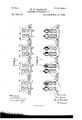
Beit known that I, WILLIAM H. MADDOGK, of Pittsburg, in the county of Allegheny and State of Pennsylvania, have invented a new and useful Improvement in Continuous Mills, of which the following is a full, clear, and exact description, reference being had to the accompanying drawings, forming part of this specitcation, in which- Figures 1 and 2 together constitute a plan view of my improved continuous mill, it being broken into two portions for the purpose of better illustration. Fig. 3 is a side elevation of the same; and Fig. #t is a longitudinal sectional view of Figs. 1 and 2, illustrating the relative proportions of the driving gears. Fig. 5 is an end elevation of the mill. Figs. 6 to 17 inclusive are detail views of the passes in the rolls, illustrating the reductions of a billet in a three-pass mill. Figs. 1S to 25, inclusive, are detail views of the passes employed in rolling sheet plates; and Fig. 26 is an enlarged detail view of asingle pass, showing the angle of the collar and fillet of the rolls.
Like symbols of reference indicate like parts in each.
My invention relates to the construction of continuous mills, and is designed to greatly simplify and compact this class of mills, to lessen the amount of hand labor required therewith, and reduce the number of motors required, as Well as to produce a continuous mill which may he used without any twisting or turning of the metal between the rolls.
To that end it consists of a continuous mill composed of a series of double sets of rolls having their passes in the same line, each set of rolls having a dummy pass in line with the reduction pass of the other set in the same housing, and each set of rolls being rotated at a higher rate of speed than the corresponding set in the preceding housing.
It also consists in the shape and relation of the succeeding passes in the rolls, whereby the turning of the metal is avoided, as Well as in the construction and arrangement of the parts as hereinafter more fully described and set forth in the claims.
In the drawings, 2 indicates a crank shaft actuated from a suitable motor and provided with a pinion 3 intermeshing with a toothed Wheel 4 upon a shaft 5. rlhe shaft extends the entire length of the mill, and is provided with bevel-wheels 6, 7, 8 and 9, which serve to drive the successive sets of rolls in the mill.
The mill proper, as shovvn in Figs. 1 and 2, consists of eight sets of rolls, numbered 10, 11, l2, 13, 14, 15, 15 and 17, respectively, though it will be understood that any number of set-s may be used. These rolls are placed in front of each other, with their passes in the same line, and are arranged in pairs, there being t-Wo sets of rolls in each housing. Each one of these sets of rolls is provided with a series of alternating reducing and dummy passes, and the other set of rolls 1n the same housing rotates in the opposite direction and has a similar series, the reducing and dummy passes alternating With each other and being arranged in opposite order so that each dummy pass in the second set is in line with a reduction pass in the first set, and vice-versa, and each reduction pass is in line with a dummy pass in the irst set. Thus the metal enters the reducing pass 1S of the first set of rolls l0, emerges through the dummy pass 19 of the set 11 Where no reduction is effected, and enters the reducing pass 20 of the set 12 before it emerges from the first set 10. From the pass 20 of rolls 12 it emerges through the dummy pass 21 of rolls 13 and enters the reduction pass 22 of set 14, and so on through the dummy pass 23,1eduction pass 2e and dummy pass 2,from which it emerges and is received upon any suitable table or support. The peripheral speeds of the sets of rolls 10, 12, 14 and 1G increase successively in accordance with the amount of 4reduction and consequent elongation of the metal, this being necessary as the space between the alternate rolls is less than the length of the metal passing therethrough. I prefer to make the alternate sets of the same diameter and increase the speed exactly in accordance with the amount of elongation, though d iderently sized rolls may be employed if desired, and their speeds Varied accordingly. The set of rolls 17 is rotated preferably at the same speed as the set 10, and the metal, after emerging from the dummy pass 25, is started back through its reduction pass 26. From the reducing pass 26 the metal emerges through the dummy pass 27 in the set 16 and thence proceeds through the reducing passes 28, 30 and 32, and the dummy passes 29, 31 and 3S. The rolls 15, 13 and 11,having IOO the reduction passes 32, 30 and 28 are rotated at a successively greater speed than the set 17 in proportion to the elongation of the metal.
It will be understood that although I have shown but two sets of passes in each set of rolls, I do not wish to restrict myself thereto, as any suitable number of passes may be employed. Moreover, the reducingand dummy passes need not necessarily alternate in each set, as there may be two or more reducing passes adjacent to each other followed by two or more dummy passes, the arrangement being immaterial. The lower rolls of sets 10, 12, 14 and 16 are driven directly through the bevel-wheels 84, 35, 36 and 37 engaging the bevel-wheels upon the shaft 5, the shafts of these lower rolls having the usual wabbler connection 38 and toothed wheels 39 engaging similar wheels 40 upon the shafts of the upper rolls, as shown in Fig. 5. Upon these lower roll shafts are also toothed wheels 41 engaging toothed wheels 42 upon the lower roll shafts of the adjacent sets of rolls in the same housing therewith, these lower shafts having intermeshing gearing with the upper shafts as in the first named set. The relative proportions of the wheels 41 and 42 and the bevel-wheels 34, 35, 36, and 37 are varied throughout the mill so as to obtain the desired speeds before mentioned. Thus, as indicated by the dotted lines in Fig. 4, starting at the first set, a toothed wheel 41 engages a small pinion 42. In the second housing the toothed wheels are of the same size. In the third set the wheel 41 becomes the pinion, while in the fourth set its relative size becomes still less.
By the connections above described it is evident that in each housing there are two sets of rolls which are rotated continuously in opposite directions and at widely different speeds, the set lO for instance having the lowest, and the adjacent set 11 the highest peripheral speed in the mill.
To do away with the necessity of turning or twisting the metal between the successive sets of rolls, I employ the system of passes shown in Figs. 6 to 17 inclusive, in each tigure the dotted lines representing the metal as it enters, and the full lines the metal as it emerges from the rolls. In each of these passes it will be seen that the lower roll is provided with a collar 45 fitting into an annular recess in the upper roll, and having a fillet 46, while on the opposite side of the pass the upper roll has a corresponding collar 47 and llet 48 fitting into the lower roll. It will also be seen that these collars and fillets change sides in the successive passes, the collar 45 being on the left hand side in the first pass, on the right hand side in the next, and so on throughout the series, the same change occurring in the upper rolls. By this arrangement the angle of the cut at the corner of the metal changes to either side of the Vertical alternately, and as the corner is turned in at each pass, no fins can be rolled upon the bar.
The metal is started in at an angle of about forty degrees in the rst pass, and thereafter is maintained at a constant angle ot' about forty-tive degrees, this angle being necessary that the metal may be drawn into the successive passes, and being maintained by the collars upon the rolls which vguide the bar and prevent its twisting. The reason for varying the angle at the first set is that the groove in the upper roll maynot cut so deeply thereinto as to weaken the roll, and after this reduction the cut not being deep enough to injure the roll, is made at the angle of fortyfive degrees. The reductions grow less throughout the series, and are somewhat as followsz-Starting with a seven by seven billet, the rst pass reduces the metal to seven by five and one-fourth, the next to five and on e-fourth square, then five and one-fourth by four, and so on,until the bar has reached the desired size. The angles of the collar 47 and fillet 48 are more clearly shown in Fig. 26, which illustrates a four by four pass, the angle of the collar being about sixty degrees, and that of the fillet about seventy degrees, the metal standing at angle of forty-five degrecs.
The manner of rolling sheet bars in this mill is shown in Figs. 18 to 25 inclusive, 1n which case a mandrel roll 49 projects into a collared roll 50, the rolls alternate, the mandrel roll being above in one pass and below in the next. A fillet is used upon the roll having adouble collar, and in this way the bevel of the ends of the sheet bars is changed in each pass, and in each case the corners are rolled in, thus preventing any formation of fins.
The grooves constituting the roll-passes are of V-shape angulvarin form and are shaped so that they shall afford alternate atting and edging passes, each successive pass being so shaped that the corners of the metal pieces shall vary in position relatively to a vertical plane passing centrally through the pass, and that the draft of the rolls and the reducing action on the metal shall occur alternately on the sides and the edges. By these means the metal which is turned at an angle to the horizontal may be passed continuously through the mill and the flatting and edging operations practiced thereon without the necessity IOO IIO
for turning the piece between the passes. Y
The saving of labor effected by this will be appreciated by those familiar with the art. The construction to which this result is primarily due, viz: the use of a series of inclined alternately atting and edging passes, I believe to be broadly new and intend to make it tho subject of a claim herein. j
It is evident that the system of passes I show herein may be employed in any continuous mill, andI do not wish to restrict myself in the broader claims to their use in the particular mill described and shown.
The advantages of my improved mill are apparent to those skilled in the art, since the same number of passes may be employed as in the ordinary continuous mill, while the space required is only a fraction of that for such continuous mill. Moreover the manual labor of handling the metal is reduced to a minimum, the lateral movement of the metal at the end being very slight. A single motor may be used to run the entire mill, and hence more perfect control thereof is attained, while, on account of the peculiar passes employed, no twisting or turning of the metal 1s necessary.
Many changes may be made in the form of the rolls and passes, the actuating connections, d:c.,.by those skilled in the art, without departure from my invention, since What I claim is- 1. A continuous mill, consisting of aseries of sets of rolls, having their passes in the same line, the alternate sets being driven in opposite directions and having registering reducing and dummy passes respectively, and means for successively increasing the speed of the alternate sets from each end of the mill; substantially as and for the purposes described.
2. A continuous mill, havinga series of sets of rolls arranged in pairs, and means for rotating the one set of each pair in an opposite direction to and at a greater speed than the other set, each set of the pair having one or more reducing passes in line with one or more dummy passes of the other set, and one or more dummy passes in line with one or more reducing passes of the other set; substantially as and for the purposes described.
3. Acontinuous mill, having a series of sets of rolls arranged in pairs, means for rotating the one set ot' each pair in an opposite direction to, and at a greater speed than the other set, each set of the pair having one or more reducing passes in line with one or more dummy passes of the other set, and one or more dummy passes in line with one or more reducing passes of the other set, and a single power shaft having actuating connections with the sets of rolls; substantially as and for the purposes described.
4. A continuons mili, having a series of sets of rolls arranged in pairs, means for rotating the one set of each pair in an opposite direction to and at a greater speed than the other set,each setof the pairhaving one or more reducing passes in line with one or more dummy passes ofthe otherset, and one or more dummy passes in line with one or more reducing passes of the other set, a single shaft having gearing connected with one set of each pair, and actuating connections between the sets of the pairs; substantially as and for the purposes described.
5. A continuous mill, having a series of sets of rolls arranged in pairs, means for rotating the one set of each pair in an opposite direction to and at a greater speed than the other set, each set of the pair having one or more reducing passes in line with one or more dummy passes of theother set, and one or more dummy passes in line with one or more reducing passes of the other set, a single power shaft having bevel-gear connections with one set of each pair, and gear-wheels connecting the sets of each pair; substantially as and for the purposes described.
6. A continuous mill, having a series of sets of rolls arranged in pairs, means for rotating the one set of each pair in an opposite direction to and at a greater speed than the other set, each set of the pair having one or more reducin g passes i-n line with one or more dummy passes ofthe other set, and one or more dummy passes in line with one or more reducing passes of the other set, power connections for the lower rolls of one set of each pair, gearing between the upper and lower rolls, and actuating connections between such set and the second set of each pair; substantially as and for the purposes described.
7. A pair ot' rolls having an inclined pass therein, each roll having a collar entirely inclosed by the other roll except for a fillet which forms one entire side of the pass; substantially as described.
8. A pair of rolls, having an angular pass therein, each roll having a collar provided with a illet having an angle of about seventy degrees to the horizontal and forming one entire side of the pass; substantially as and for the purposes described.
9. A pair of rolls, having an angular pass therein, each roll being provided with a collar having an angle of about sixty degrees to the horizontal, said collar having a filleteX- tending at about seventy degrees to the horizontal and forming one side of the pass; substantially as and for the purposes described.
l0. A series ot sets of rolls, having their passes in line with each other, the rolls of each set having inclosed collars provided with fillets forming one entire side of the pass therein, the fillet angles in alternate sets extending in opposite directions; substantially as and for the purposes described.
l1. A series of rolls having alternate flatting and edging passesinline with each other, said passes being inclined in the same direction; substantially as described.
12. A series of sets of rolls having their passes in line with each other and all inclined in the same direction, the rolls of each set having collars entirely inclosed by the other rolls except for fillets forming one entire side of the pass therein, the fillet angles in alternate sets extending in opposite directions; substantially as described.
In testimony whereof I have hereunto set my hand this 30th day of August, A. D. 1892.
y W. H. MADDOCK.
Witnesses:
R. H. Wnrr'rnnsnr,
H. M. CORWIN.
IIO
Publications (1)
| Publication Number | Publication Date |
|---|---|
| US515917A true US515917A (en) | 1894-03-06 |
Family
ID=2584724
Family Applications (1)
| Application Number | Title | Priority Date | Filing Date |
|---|---|---|---|
| US515917D Expired - Lifetime US515917A (en) | Continuous rolling-mill |
Country Status (1)
| Country | Link |
|---|---|
| US (1) | US515917A (en) |
-
0
- US US515917D patent/US515917A/en not_active Expired - Lifetime
Similar Documents
| Publication | Publication Date | Title |
|---|---|---|
| KR900000294B1 (en) | Contineous rolling method and continuous rolling mill | |
| US515917A (en) | Continuous rolling-mill | |
| WO2000048756A1 (en) | Wire rod rolling line | |
| US1310206A (en) | Rolling mill | |
| US1190698A (en) | Method of and apparatus for cold-rolling metal. | |
| US1385644A (en) | Universal mill | |
| US372747A (en) | Reversing rolling-mill | |
| JP3321353B2 (en) | Rolling method for bar and wire rods and rolling equipment used therefor | |
| US1420239A (en) | brock | |
| US718476A (en) | Mill for rolling seamless tubing. | |
| US970559A (en) | Rolling-mill plant. | |
| US69734A (en) | Improved machine for making nails for horseshoes | |
| US688751A (en) | Rolling-mill. | |
| US370522A (en) | Continuous rolling-mill | |
| US328591A (en) | lenox | |
| US1123797A (en) | Continuously-operating rolling-mill. | |
| US1271361A (en) | Continuous rolling-mill. | |
| US195130A (en) | Improvement in screw-gearing for rolling-mills | |
| US275309A (en) | Metal-rolling mill | |
| US645306A (en) | Rolling-mill. | |
| USRE11280E (en) | Rolling-mill plant | |
| US3383898A (en) | Continuous rolling mill | |
| US444049A (en) | Rod-mill | |
| US1348230A (en) | Mill-train for the manufacture of small and medium iron bars | |
| US435810A (en) | fitch |