US515101A - Wheel - Google Patents
Wheel Download PDFInfo
- Publication number
- US515101A US515101A US515101DA US515101A US 515101 A US515101 A US 515101A US 515101D A US515101D A US 515101DA US 515101 A US515101 A US 515101A
- Authority
- US
- United States
- Prior art keywords
- hub
- wheel
- collar
- axle
- balls
- Prior art date
- Legal status (The legal status is an assumption and is not a legal conclusion. Google has not performed a legal analysis and makes no representation as to the accuracy of the status listed.)
- Expired - Lifetime
Links
- 230000008901 benefit Effects 0.000 description 4
- 239000003245 coal Substances 0.000 description 3
- 238000010276 construction Methods 0.000 description 3
- 238000005065 mining Methods 0.000 description 3
- 238000012856 packing Methods 0.000 description 3
- XLYOFNOQVPJJNP-UHFFFAOYSA-N water Substances O XLYOFNOQVPJJNP-UHFFFAOYSA-N 0.000 description 3
- 239000000428 dust Substances 0.000 description 2
- 241001331845 Equus asinus x caballus Species 0.000 description 1
- CWYNVVGOOAEACU-UHFFFAOYSA-N Fe2+ Chemical compound [Fe+2] CWYNVVGOOAEACU-UHFFFAOYSA-N 0.000 description 1
- 229910000831 Steel Inorganic materials 0.000 description 1
- 229910000754 Wrought iron Inorganic materials 0.000 description 1
- 238000005266 casting Methods 0.000 description 1
- 238000001816 cooling Methods 0.000 description 1
- 230000001788 irregular Effects 0.000 description 1
- 238000005304 joining Methods 0.000 description 1
- 230000001050 lubricating effect Effects 0.000 description 1
- 238000004519 manufacturing process Methods 0.000 description 1
- 239000002184 metal Substances 0.000 description 1
- 229910052751 metal Inorganic materials 0.000 description 1
- 238000005096 rolling process Methods 0.000 description 1
- 239000010959 steel Substances 0.000 description 1
- 239000002699 waste material Substances 0.000 description 1
Images
Classifications
-
- B—PERFORMING OPERATIONS; TRANSPORTING
- B60—VEHICLES IN GENERAL
- B60B—VEHICLE WHEELS; CASTORS; AXLES FOR WHEELS OR CASTORS; INCREASING WHEEL ADHESION
- B60B27/00—Hubs
- B60B27/0005—Hubs with ball bearings
Definitions
- Our improvements are directed to provision whereby in the use of ball bearings to eect the entire saving of car oil and the time of an oiler; to prevent the wear of the journal; to lessen the power required to start and to pull the car and thereby lessen the expense of the outfit in the number of mules and drivers; to render the wheel as durable as that of a self oiling wheel and give it a perfectly balanced and true position upon the balls.
- these are highly important advantages, and so far as we know and can iind there is not in use in the coal and mining trades in this country, cars having Wheels which obtain these advantages or any of them.
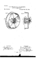
- Figure 1 shows such a wheel in perspective with a portion of the fixed axle collar removed to expose its relation and construction to the Wheel hub, its groove, and to the row of bearing balls; and
- Fig. 2 is a central cross section of the wheel showing it as mounted upon the axle arm and its engagement with the rims of the xed and of the adjustable collars.
- This chilling of the Wheel hub is made to give greater strength and hardness to the hub ot the wheel, and to provide hard and smooth confining seats for the balls upon Which the Wheel is mounted.
- These seats are formed by grooves 2 and 16 concave in their cross section around each end of the hub standing outwardly and upwardly at the junction of the inner Wall of the central opening and the ends of the hub. These grooves must be perfectly smooth and true, and the chilling gives the perfect finish to their surfaces, and exact symmetrical position of these grooves at each end of the hub.
- the axle 5 is formed with the bearing arm or journal 6 which is screw'threaded at its end, and has a shoulder 7 at the junction of the arm with the axle.
- a collar 8 is forced, that is to say, it is compressed by special machinery so as to insure solidity and trueness as a fixed part of the axle.
- the diameter of this collar is a little less than that of the wheel-hub and its circumference terminates in an inward standing rim 9, the purpose of which we will presently state.
- the inner Wall of this lixed collar at its junction with the axle arm is formed with an cannular seat 10 which is concave in its cross section and stands inward and downward and forms a seating and raceway for the balls, co-incident the annular concave seat 2 symmetrical with that formed in each end of the hub and within and between which a row of balls 16 is confined so as to havea free rolling action upon the walls of said grooves.
- the collar is made of hardened wrought iron or steel that all the wear surfaces will be equally hard.
- a collar 12 of identical construction with the fixed collar is screwed upon the threaded end of the axle arm and held in place by a jam nut 13 and an interposed washer 14.
- Each end of the hub outside of and concentric with the ball seating grooves is formed With a groove 18 deep enough to receive both packing and the rims 9, respectively of the collars,whereby said rims are caused to stand within and be embedded in the packing and form a water and dust tight joint for the protection of the bearings.
- the rims of the collars By having the rims of the collars extend into the grooves in both ends of the hub of the wheel, the rims serve to shed the water from the joints over the outer sides of the collars. Because as the rims extend into the grooves they cross the face line of the hub and instead of forming ay gutter to catch and hold water andv dust they turn it off.
- the fixed collar 8 and its rim 9 also serves as the means of supporting and centering the wheel in placing it upon the axle.
Landscapes
- Engineering & Computer Science (AREA)
- Mechanical Engineering (AREA)
- Rolling Contact Bearings (AREA)
Description
(No Model.)
s. D. WRIGHT a. J. W. HORNSE'Y.
ROLLER BEARING WHEEL.
No. 515,101. Patented Feb. 20, 1894.
WHWESSES UNrrnD STATES BrrnNr Fries.
SAMSON D. WRIGHT AND JOHN W. HORNSEY, OF CLEVELAND, OHIO, ASSIGNORS TO THE BALL BEARING CAR WHEEL MANUFACTURING COMPANY, OF SAME PLACE.
ROLLER-BEARING WHEEL.
SPECIFICATION forming part of Letters Patent No. 515,101, dated February 20, 1894.
Application filed .Tune 7,1893. lSerial No. 476,845. (No model.)
To all whom it r11/ay concern/.-
Be it known that we, SAMSON D. WRIGHT and JOHN W. HoRNsEY, citizens of the United States, and residents of the city of Cleveland, in the county of Cuyahoga and State of Ohio, have invented certain new and usefullrnprovements in Roller Bearing Wheels, of which the following is a specification.
For coal, freight and mining cars the Waste of oil for lubricating the journals of the wheels is immense. This is not only very expensive but is objectionable in the greasy condition of the running gear and the tracks produced thereby and in the gumming of the oil in cold weather.
Our improvements are directed to provision whereby in the use of ball bearings to eect the entire saving of car oil and the time of an oiler; to prevent the wear of the journal; to lessen the power required to start and to pull the car and thereby lessen the expense of the outfit in the number of mules and drivers; to render the wheel as durable as that of a self oiling wheel and give it a perfectly balanced and true position upon the balls. For such cars these are highly important advantages, and so far as we know and can iind there is not in use in the coal and mining trades in this country, cars having Wheels which obtain these advantages or any of them.
Figure 1 shows such a wheel in perspective with a portion of the fixed axle collar removed to expose its relation and construction to the Wheel hub, its groove, and to the row of bearing balls; and Fig. 2 is a central cross section of the wheel showing it as mounted upon the axle arm and its engagement with the rims of the xed and of the adjustable collars.
of the coal and mining trades, as its use has abundantlyshown. This chilling of the Wheel hub is made to give greater strength and hardness to the hub ot the wheel, and to provide hard and smooth confining seats for the balls upon Which the Wheel is mounted. These seats are formed by grooves 2 and 16 concave in their cross section around each end of the hub standing outwardly and upwardly at the junction of the inner Wall of the central opening and the ends of the hub. These grooves must be perfectly smooth and true, and the chilling gives the perfect finish to their surfaces, and exact symmetrical position of these grooves at each end of the hub. To do this we found it necessary after much experimenting, to use a chill-core of two separable counterparts and to so form them that while making the central opening of the wheel-hub, their outer Walls must taper so as to produce the conical walls 3 seen `in Fig. 2, meeting at a line 4 preferably central With the width of the hub. This allows the placing and withdrawal of the separable chill-cores to chill the hub and to forni at the same time the finished ballretaining hardened seats, so that the wheel when cast., will be complete with chilled hub and chilled and finished ball races at each end joining the conical walls of its central opening. It .is evident that without such separable counter-part chill-cores, the wheel could not be produced with a chilled-hub, for the reason that the contact of the hot metal upon the chill-cores will cause them to eX- pand, while the hub in cooling contracts, and were it not therefore, for the conical form of the inner walls of the hub as seen, it would be impossible to withdraw the chill-cores from the hub. As this chill casting part of our invention, however, is made the subject of a separate and distinct application for a patent 'by us, it is deemed unnecessary to more particularly describe it herein.
The axle 5 is formed with the bearing arm or journal 6 which is screw'threaded at its end, and has a shoulder 7 at the junction of the arm with the axle. Upon this shoulder a collar 8 is forced, that is to say, it is compressed by special machinery so as to insure solidity and trueness as a fixed part of the axle. The diameter of this collar is a little less than that of the wheel-hub and its circumference terminates in an inward standing rim 9, the purpose of which we will presently state. The inner Wall of this lixed collar at its junction with the axle arm is formed with an cannular seat 10 which is concave in its cross section and stands inward and downward and forms a seating and raceway for the balls, co-incident the annular concave seat 2 symmetrical with that formed in each end of the hub and within and between which a row of balls 16 is confined so as to havea free rolling action upon the walls of said grooves. The collar is made of hardened wrought iron or steel that all the wear surfaces will be equally hard. A collar 12 of identical construction with the fixed collar is screwed upon the threaded end of the axle arm and held in place by a jam nut 13 and an interposed washer 14. Between this collar and the outer end of the hub a row of balls 15 is conned between and within co-incident hub and collarv seats, 16 and 17, and upon these two end rows of balls, the wheel is seated, balancedvand supported free of the axle arm, and revolves freely upon said balls. We com-- press the inner collar upon the axle so that it will serve as a fixed abutmentagainst which rthe perfect alignment of the wheel is both made and maintained by the adjustable collar and nut. For, were this collar S free for rotation upon the axle-arm it would produce wear both upon the arm and upon the shoulder and cause an unsteady and untrue and wabbling support of the wheel at that side and thereby not only destroy its alignment in relation to the axle, but the perfect balance of the Wheels upon the balls and thereby produce irregular wear at every point. Indeed,.but for this provision of the fixed seating abutment for the inner row of balls, the obj ect and purpose of our invention would be practically destroyed. It is with this fixed ball seating abutment that the adjusting func-v tion of the outer ball seating collar, is made usefully operative to take up the wear of the parts and to maintain the true and easy and smooth working of the wheel. Each end of the hub outside of and concentric with the ball seating grooves is formed With a groove 18 deep enough to receive both packing and the rims 9, respectively of the collars,whereby said rims are caused to stand within and be embedded in the packing and form a water and dust tight joint for the protection of the bearings.
By having the rims of the collars extend into the grooves in both ends of the hub of the wheel, the rims serve to shed the water from the joints over the outer sides of the collars. Because as the rims extend into the grooves they cross the face line of the hub and instead of forming ay gutter to catch and hold water andv dust they turn it off. The fixed collar 8 and its rim 9 also serves as the means of supporting and centering the wheel in placing it upon the axle. In this operation the axle is supported vertically and the balls put into the collar recess and rest against the rim, the wheel is then put upon the axle in a horizontal position and rests upon the balls and rim of the collar and it is in this position that the collar and rim forms an annular abutment and centering device supporting the wheel in its true set at right angles to the axle. The second set of balls is then placed with-in the groove in the upper end of the Wheel-hub and the outer collar screwed upon the axle. The driving action of this outer collar forces the bearing balls into their seats while the rim of this screw collar, bearing within lthe hub groove completes the perfect alignment of the wheel upon its axle. In this operation it is important that the grooves should be concentrically co-incident with each other so that the pressure of the rim shall be at opposite points upon the hub. The placing of the packing containing grooves in the ends of the hub, we foundv to give the advan tage of allowing the collars to be made of a diameter to bring their rims close to the edges of the hub seats, and thereby cause the hub edges to strike the outer side of the balls and put them in their seats in tting' the parts together. This advantage could not be obtained if the grooves were placed in the collars, because such latter construction would entail the necessity of having to lower and support the Wheel on the axle awayfrom the fixed collar, to place the balls upon and within the hub-seat and then reverse the position of the wheel and axle to put the other collar and balls in place. Owing to the great weight of the Wheel and axle this operation requires much labor, time and expense,.which we save by placing the grooves in the hub ends as shown. y
We claim as our improvement- 1. In a roller bearing wheel, in combination, the wheel-hub formed with annularconcave chilled seats at each end and with concentric grooves in each end, the axle-arm hav.- ing the shoulder 7 Aand the screwthreaded end, the collar 8 iixed upon said arm and shoulder and having the annular concave seat, and the rim 9 iitting intol one of said hub-grooves, the screw-collar 12 having the annular concave seat and the annular rim 9 fitting into lthe groove at the other endV of said hub, and the balls, substantially as described.
2. In a roller bearing wheel, in combination, the wheel-hub formed with the concentric grooves in its end Walls, the axle-arm having the screw-threaded end, the fixed collar 8,- and the screw collar 12, both said col- IIO lars having circumferential rims fitting into signed this specification in the presence of said hub-grooves, and the bearing-balls con- Witnesses. fined Within suitable concave seats formed in SAMSON D. WRIGHT. the hub and by the said collars whereby Wa- 5 ter shedding closuresV are formed for the bear- JOHN W HORNSEY ing balls and seats, between rotary and non- Witnesses: rotary parts, as described. M. MILLARD,
In testimony whereof we have hereunto E. F. WRIGHT.
Publications (1)
| Publication Number | Publication Date |
|---|---|
| US515101A true US515101A (en) | 1894-02-20 |
Family
ID=2583909
Family Applications (1)
| Application Number | Title | Priority Date | Filing Date |
|---|---|---|---|
| US515101D Expired - Lifetime US515101A (en) | Wheel |
Country Status (1)
| Country | Link |
|---|---|
| US (1) | US515101A (en) |
-
0
- US US515101D patent/US515101A/en not_active Expired - Lifetime
Similar Documents
| Publication | Publication Date | Title |
|---|---|---|
| US515101A (en) | Wheel | |
| US1638957A (en) | Journal bearing | |
| US958143A (en) | Self-adjusting casing for roller-bearings. | |
| US990946A (en) | Roller-bearing. | |
| US2033156A (en) | Bearing | |
| US602589A (en) | Thrust-bearing | |
| US515102A (en) | Samson d | |
| US1178526A (en) | Roller-bearing. | |
| US580498A (en) | Ball-bearing | |
| US642704A (en) | Roller-bearing car-wheel. | |
| US546557A (en) | Ball-bearing | |
| US454075A (en) | Axle-journal and journal-bearing | |
| RU215867U1 (en) | ANGULAR CONTACT BEARING CASSETTE TYPE FOR RAILWAY BOX | |
| US590627A (en) | Court-house | |
| US438902A (en) | Half to jacob g | |
| US544451A (en) | Roller-bearing for carriage-spindles | |
| US583911A (en) | Ball-bearing | |
| US609777A (en) | Roller-bearing | |
| US1203800A (en) | Mine-car wheel. | |
| US647113A (en) | Antifriction-bearing for vehicle-wheels. | |
| US570860A (en) | Bicycle ball-bearing | |
| US1247859A (en) | Antifriction-bearing. | |
| US124618A (en) | Improvement in car-axle lubricators | |
| US1324638A (en) | bradshaw | |
| US2025342A (en) | Tubular axle and roller bearing assembly |