US5148870A - Well tieback connector sealing and testing apparatus - Google Patents
Well tieback connector sealing and testing apparatus Download PDFInfo
- Publication number
- US5148870A US5148870A US07/753,532 US75353291A US5148870A US 5148870 A US5148870 A US 5148870A US 75353291 A US75353291 A US 75353291A US 5148870 A US5148870 A US 5148870A
- Authority
- US
- United States
- Prior art keywords
- tieback
- grooves
- sealing area
- passage
- seal
- Prior art date
- Legal status (The legal status is an assumption and is not a legal conclusion. Google has not performed a legal analysis and makes no representation as to the accuracy of the status listed.)
- Expired - Fee Related
Links
- 238000012360 testing method Methods 0.000 title claims abstract description 90
- 238000007789 sealing Methods 0.000 title claims abstract description 73
- 238000002955 isolation Methods 0.000 claims abstract description 58
- 238000004891 communication Methods 0.000 claims description 15
- 239000012530 fluid Substances 0.000 claims description 12
- 239000002184 metal Substances 0.000 claims description 9
- 238000000034 method Methods 0.000 claims description 4
- 238000012544 monitoring process Methods 0.000 claims 1
- 238000005553 drilling Methods 0.000 description 14
- 238000004519 manufacturing process Methods 0.000 description 6
- 230000006835 compression Effects 0.000 description 2
- 238000007906 compression Methods 0.000 description 2
- 238000006073 displacement reaction Methods 0.000 description 1
- 229920001971 elastomer Polymers 0.000 description 1
- 239000000806 elastomer Substances 0.000 description 1
- 230000013011 mating Effects 0.000 description 1
- 238000005086 pumping Methods 0.000 description 1
- 125000006850 spacer group Chemical group 0.000 description 1
Images


Classifications
-
- E—FIXED CONSTRUCTIONS
- E21—EARTH OR ROCK DRILLING; MINING
- E21B—EARTH OR ROCK DRILLING; OBTAINING OIL, GAS, WATER, SOLUBLE OR MELTABLE MATERIALS OR A SLURRY OF MINERALS FROM WELLS
- E21B33/00—Sealing or packing boreholes or wells
- E21B33/02—Surface sealing or packing
- E21B33/03—Well heads; Setting-up thereof
- E21B33/035—Well heads; Setting-up thereof specially adapted for underwater installations
- E21B33/038—Connectors used on well heads, e.g. for connecting blow-out preventer and riser
Definitions
- This invention relates in general to a tieback apparatus for a subsea well, and in particular to a means for sealing the tieback connector and testing the seal.
- mudline tieback connections are employed, particularly for exploratory wells.
- a mudline tieback connection rather than utilize a subsea pressure containing wellhead, all of the casing strings will extend to the drilling rig.
- the pressure control will thus be at the drilling rig rather than subsea.
- Tieback connectors will be located at the subsea wellhead housing to connect the casing strings that are cemented in place to tieback strings that extend to the surface drilling vessel.
- the operator may temporarily abandon the well after drilling by removing the tieback strings extending from the casing strings to the surface. The operator will place a cap on the subsea structure until he later returns for running production equipment.
- the tieback connector for each string includes an upward facing tubular tieback member located at the subsea wellhead at the upper end of each casing string that will serve subsequently to be connected to a tieback string for production.
- This lower tieback member has a set of running grooves, normally left-hand threads, that were utilized when the casing string was initially run. Also, the lower tieback member will have a set of tieback grooves, which may be threads or grooves, for securing to a subsequent tieback string when it is desired to complete the well for production.
- the operator When it is desired to complete the wells for production, the operator will position a production platform over the well or wells. The operator removes the cap from the lower tieback member and lowers a tieback string back into engagement with the lower tieback member.
- the tieback string has an upper tubular tieback member on its lower end that stabs into and latches with the lower tieback member.
- the upper and lower tieback members have a seal that seals the connection from the annulus and bore. The upper and lower tieback members make up the tieback connector.
- the operator must test the tieback connection to assure that the tieback connector does not leak to the annulus.
- an operator would lower an isolation test tool which had an upper elastomeric seal and a lower elastomeric seal. He would set the upper seal in the upper tieback member bore and the lower seal in the casing below the lower tieback member. The operator would apply pressure to this area to determine if leakage exists.
- a tieback connector that has provisions for enabling testing after the upper tieback member is latched into the lower tieback member.
- the tieback connector has conventional running grooves and tieback grooves for latching together.
- At least one sealing area is located in the lower tieback member below at least one of the sets of running grooves and tieback grooves.
- An upper sealing area is located in the lower tieback member above the lower sealing area and above at least one of the sets of running grooves and tieback grooves.
- the upper tieback member has upper and lower seals for mating with the upper and lower sealing areas on the lower tieback member. The upper and lower seals and sealing areas will seal between the upper and lower tieback members once made up.
- test passage is located between the upper and lower seals. This test passage extends from the axial passage of the upper tieback member to the exterior of the upper tieback member.
- the isolation test tool is lowered into the assembly.
- the isolation test tool has an upper seal that seals above the test passage and a lower seal that seals in the upper tieback member below the test passage. Both of the areas engaged by the isolation test seals are undamaged sealing surfaces.
- the operator applies pressure through the isolation test tool to determine if either the upper and lower seals between the tieback members leaks.
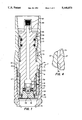
- FIG. 1 is a sectional view illustrating a tieback connector constructed in accordance with this invention, and further showing an isolation test tool located within the tieback connector.
- FIG. 2 is a partial enlarged sectional view of a portion of the tieback connector of FIG. 1, showing the isolation test tool prior to energizing the test seals.
- FIG. 3 is a partial enlarged sectional view similar to FIG. 4, but showing the isolation test tool seals energized and showing test pressure being applied.
- FIG. 4 is a partial enlarged view of the upper seal and sealing area for the tieback connector of FIG. 1.
- tieback connector 11 includes a lower tieback member 13 extending upward from the sea floor.
- Lower tieback member 13 will be supported within a wellhead (not shown) and will face upward.
- Lower tieback member 13 will be secured to a string of casing (not shown) extending into the well.
- the lower tieback member 13 has an axial passage 15 and a receptacle 14 on its upper end.
- the lower tieback member 13 would have been initially secured to a string of casing (not shown) and lowered into the well by a running tool (not shown).
- the running tool would be connected to the lower end of a string of pipe extending to the drilling platform and would remain in engagement during further drilling operations. The running tool would be retrieved when the well is temporarily abandoned.
- Receptacle 14 is of a larger diameter than the lower portion of bore 15 and has a set of running grooves 17 and a set of tieback grooves 19.
- Running grooves 17 are shown to be located below the tieback grooves 19.
- Running grooves 17 and tieback grooves 19 may be of various types of engagement profiles used in tieback connectors.
- the running grooves 17 comprise a helical left-hand thread.
- the tieback grooves 19 comprise a right-hand helical thread.
- the inner diameter of the tieback grooves 19 is larger than the inner diameter of the running grooves 17.
- an upper tieback member 21 will be lowered into the receptacle 14 of the lower tieback member 13.
- Upper tieback member 21 will be secured to the lower end of a string of casing (not shown), which extends to a platform at the surface.
- Upper tieback member 21 has an axial bore 22.
- Upper tieback member 21 carries a metal split ring or latch 23 that ratchets into the tieback grooves 19 to secure the members together.
- Latch 23 is keyed to the upper tieback member 21 for rotation therewith. The upper tieback member 21 will latch into place, then a slight amount of rotation of the upper tieback member 21 will lock the tieback members 13, 21 together.
- Latch 23 has external threads 25 (FIG. 2) and internal back up shoulders 27. The back up shoulders 27 engage shoulders 29 located on the exterior of upper tieback member 21.
- Latch 25 be of various types, but is shown to be the type that is described in U.S. Pat. No. 4,607,865, David W. Hughes, Aug. 26, 1986.
- Upper tieback member 21 has a nose 31 that extends into the lower tieback member 13. Nose 31 has a lower seal 33 located on nose 31. Seal 33 is a tapered or conical metal seal, having also an elastomer. Seal 33 mates with a conical smooth lower seal area 35 located in the receptacle 14. The lower sealing area 35 at its minimum has a greater diameter than the inner diameter of the bore 15 located below receptacle 14. The prior running tool (not shown) for the lower tieback member 13 would provide protection for the lower seal area 35 during drilling operations conducted through the lower tieback member 13. The engagement of the lower tieback seal 33 and the lower sealing area 35 is an interference, metal-to-metal engagement.
- the upper tieback member 21 also has an upper tieback seal 37.
- Upper tieback seal 37 is positioned to engage an upper sealing area 39 located between the running threads 17 and the tieback threads 19.
- the upper tieback seal 37 is preferably of a metal-to-metal type but could be of various types. Preferably it comprises an annular band 37 that protrudes out and interferingly engages the upper sealing area 39.
- the upper sealing area 39 is preferably a smooth cylindrical surface.
- the upper sealing area 39 has an inner diameter that is greater than the crest diameter of the running threads 17.
- the running tool (not shown) will be engaging the running threads 17 and thus will protect the upper sealing area 39 from damage of any drill pipe.
- An elastomeric seal 40 is located above upper seal 37 and above latch 23 for engaging the bore 15 at the upper end of receptacle 14.
- test passage 43 extends from the bore 22 of upper tieback member 21 radially outward to the exterior of upper tieback member 21. Test passage 43 is located between the upper tieback seal 37 and the lower tieback seal 33. Test passage 43 thus will align with the running threads 17 when the upper tieback member 21 has fully engaged the lower tieback member 13. Test passage 43 in the preferred embodiment does not contain any check valves, rather remains continuously open.
- isolation test tool 45 on drill pipe (not shown) into bore 22 of upper tieback member 21.
- Isolation test tool 45 may be of various types. In the preferred embodiment, isolation test tool 45 has threads 47 on its upper end for securing to the drill pipe (not shown). Isolation test tool 45 has an axial passage 49 extending through it that coincides with the longitudinal axis of the upper tieback member 21. Isolation test tool 45 has a cap 51 on its lower end. A fluid displacement passage 53 extends through cap 51.
- Isolation test tool 45 has an upper isolation seal 55 and a lower isolation seal 57.
- Isolation seals 55, 57 are large elastomeric seals for engaging the bore 22 of the upper tieback member 21. When landed into place, upper isolation seal 55 will locate above test passage 43, and lower isolation seal 57 will locate below test passage 43. The isolation seals 55, 57 engage a smooth sealing surface formed in bore 22. As the upper tieback member 21 has not received any drill pipe during any earlier drilling operations, these surfaces will be undamaged due to engagement with any drilling equipment.
- the upper and lower isolation seals 55, 57 each have compression rings 59 spaced above and below them.
- Compression rings 59 are metal rings used to deform the seals 55, 57 when pressure is applied to the inner diameters of the seals 55, 57.
- Energizing passages 61 extend from the isolation tool axial passage 49 to the inner diameters of each of the isolation seals 55, 57. Energizing passages 61 are used to convey fluid pumped down the drill pipe to the isolation seals 55, 57 to cause them to deform into tight sealing engagement.
- a communication passage 63 extends radially from isolation tool axial passage 49. Communication passage 63 extends through the body of isolation test tool 45 and through a spacer ring 65 located on the exterior of the body of isolation test tool 45. Communication passage 63 does not join the energizing passages 61. When isolation test tool 45 is installed at the proper test position, communication passage 63 will be aligned with the test passage 43. This allows fluid pumped down the drill string to flow through the communication passage 63 and test passage 43 into the annular space between the upper and lower tieback seals 33, 37.
- valve 67 will block the communication passage 63 until the isolation seals 55, 57 have been fully energized by pressure from the drill pipe.
- Valve 67 is a cup shaped element that has a seal 69 on its exterior for sealing in the test tool passage 49. Seal 69 will in all cases be located below the energizing passage 61. While the valve 67 is in the upper position, as shown in FIG. 1, seal 69 will be located above communication passage 63. Valve 67 will move axially between the upper position shown in FIG. 2 and the lower position shown in FIG. 3.
- Valve 67 has a lower portion 71 that extends into a socket 73 provided in the upper end of cap 51.
- a series of belleville springs 75 locate between cap 51 and a downward facing shoulder 76 from valve 67. When moving to the lower position shown in FIG. 3, the springs 75 compress and urge the valve 67 back toward the upper position. The pressure of the fluid pumped down the axial passage 49 from the platform will force the valve 67 to the lower position once the pressure reaches a minimum level. At that minimum level, the isolation seals 55, 57 will be fully energized.
- the isolation test tool 45 will latch into the upper tieback member 21 in various manners.
- the tool has a split ring 77 that engage a recess 79 to locate the isolation test tool 45 at the proper position.
- spring-biased keys 81 located above split ring 77 engage splines 83 in the upper tieback member 21. Keys 81 engage splines 83 to permit engagement rotation of the upper tieback member 21 into the lower tieback member 13 through torque applied with the drill pipe and torque test tool 45.
- the lower tieback member 13 will have previously been connected to a string of casing (not shown), lowered into the sea, and the casing cemented into place. During that procedure, the running tool (not shown) for the lower tieback member 13 will have engaged the running threads 17. Normally, further drilling operations would have been performed through the casing and the lower tieback member 13. After drilling operations are completed, the running string will be removed. This leaves the lower tieback member 13 at the subsea well. A cap may be installed.
- the operator lowers the isolation test tool 45 on a string of conduit into the bore 22 of upper tieback 21.
- Split ring 77 and keys 81 will engage the recess 79 and splines 83, respectively.
- the operator then applies pressure to the isolation tool passage 49 by pumping fluid down the drill pipe from the platform. This fluid flows through the energizing passages 61, shown in FIG. 2, to cause the isolation seals 55, 57 to sealingly engage the upper tieback member bore 22 above and below the test passage 43.
- valve 67 will move downward. This exposes the communication passage 63. Then, the fluid will flow through the test passage 43 to the annular space between the tieback seals 33, 37. The operator will monitor the annulus surrounding the tieback connection 11 to determine if any leakage past the upper tieback seal 37 and past seals 40 exist. If not, the operator releases the tieback pressure and removes the isolation test tool 45.
- the upper tieback seal 37 will serve as the seal to prevent flow from the upper tieback member bore 22 to the exterior of the tieback connection 11.
- the lower tieback seal 33 will have no further function because the test passage 43 will remain open during further operations.
- the tieback connector enables a test tool to isolate and test a tieback connection seal without having to seal in the bore of the lower tieback member or in casing below the lower tieback member receptacle.
- the isolation test tool seals need only seal against smooth new surfaces in the upper tieback member, which will not have been damaged by drilling equipment during earlier operations.
- the valve located in the isolation test tool assures that the isolation test seals are properly energized before pressure is supplied for testing.
Landscapes
- Life Sciences & Earth Sciences (AREA)
- Engineering & Computer Science (AREA)
- Geology (AREA)
- Mining & Mineral Resources (AREA)
- Physics & Mathematics (AREA)
- Environmental & Geological Engineering (AREA)
- Fluid Mechanics (AREA)
- General Life Sciences & Earth Sciences (AREA)
- Geochemistry & Mineralogy (AREA)
- Investigating Strength Of Materials By Application Of Mechanical Stress (AREA)
Abstract
Description
Claims (20)
Priority Applications (2)
| Application Number | Priority Date | Filing Date | Title |
|---|---|---|---|
| US07/753,532 US5148870A (en) | 1991-09-03 | 1991-09-03 | Well tieback connector sealing and testing apparatus |
| GB9218576A GB2259369B (en) | 1991-09-03 | 1992-09-02 | Well tieback connector sealing and testing apparatus |
Applications Claiming Priority (1)
| Application Number | Priority Date | Filing Date | Title |
|---|---|---|---|
| US07/753,532 US5148870A (en) | 1991-09-03 | 1991-09-03 | Well tieback connector sealing and testing apparatus |
Publications (1)
| Publication Number | Publication Date |
|---|---|
| US5148870A true US5148870A (en) | 1992-09-22 |
Family
ID=25031033
Family Applications (1)
| Application Number | Title | Priority Date | Filing Date |
|---|---|---|---|
| US07/753,532 Expired - Fee Related US5148870A (en) | 1991-09-03 | 1991-09-03 | Well tieback connector sealing and testing apparatus |
Country Status (2)
| Country | Link |
|---|---|
| US (1) | US5148870A (en) |
| GB (1) | GB2259369B (en) |
Cited By (13)
| Publication number | Priority date | Publication date | Assignee | Title |
|---|---|---|---|---|
| US5249629A (en) * | 1992-09-28 | 1993-10-05 | Abb Vetco Gray Inc. | Full bore casing hanger running tool |
| US5607019A (en) * | 1995-04-10 | 1997-03-04 | Abb Vetco Gray Inc. | Adjustable mandrel hanger for a jackup drilling rig |
| US6575243B2 (en) * | 2001-04-16 | 2003-06-10 | Schlumberger Technology Corporation | Zonal isolation tool with same trip pressure test |
| US20030127534A1 (en) * | 2002-01-09 | 2003-07-10 | Firestone Roy J. | Truck wash automatic chemical ratio proportioning |
| US20030207730A1 (en) * | 2002-05-01 | 2003-11-06 | Braithwaite David M. | Multi-purpose golf accessory |
| US20040069493A1 (en) * | 2001-05-24 | 2004-04-15 | Borak Eugene A. | One-trip wellhead installation systems and methods |
| US6752397B2 (en) * | 2001-12-18 | 2004-06-22 | Schlumberger Technology Corporation | Redundant metal-metal seal |
| US20040216889A1 (en) * | 2003-05-01 | 2004-11-04 | Fraser James M. | Expandable tieback |
| US20050213898A1 (en) * | 2004-03-24 | 2005-09-29 | Schlumberger Technology Corporation | Cable Splice Protector |
| WO2010105344A1 (en) * | 2009-03-16 | 2010-09-23 | Noetic Engineering 2008 Inc. | Fixture for evaluating a metal-to-metal seal between tubular components and method of use of same. |
| US8561995B2 (en) | 2009-06-30 | 2013-10-22 | Vetco Gray Inc. | Metal-to-metal annulus seal arrangement |
| US9217307B2 (en) | 2010-03-02 | 2015-12-22 | Fmc Technologies, Inc. | Riserless single trip hanger and packoff running tool |
| WO2017007628A1 (en) * | 2015-07-06 | 2017-01-12 | Cameron International Corporation | Testable backpressure valve system |
Citations (8)
| Publication number | Priority date | Publication date | Assignee | Title |
|---|---|---|---|---|
| US4519633A (en) * | 1983-06-29 | 1985-05-28 | Fmc Corporation | Subsea well casing tieback connector |
| US4653589A (en) * | 1985-06-17 | 1987-03-31 | Vetco Gray Inc | Mudline casing hanger tieback adaptor with adjustable load ring |
| US4696493A (en) * | 1986-06-11 | 1987-09-29 | Vetco-Gray Inc. | Subsea wellhead tieback system |
| US4781387A (en) * | 1987-06-15 | 1988-11-01 | Braugh Benton F | Metal to metal subsea casing hanger seal |
| US4919454A (en) * | 1989-02-14 | 1990-04-24 | Vetco Gray Inc. | Tieback connector with protective landing sleeve |
| US4941691A (en) * | 1988-06-08 | 1990-07-17 | Dril-Quip, Inc. | Subsea wellhead equipment |
| US4976458A (en) * | 1989-10-16 | 1990-12-11 | Vetco Gray Inc. | Internal tieback connector |
| US5080173A (en) * | 1991-01-30 | 1992-01-14 | Abb Vetco Gray Inc. | Tieback wellhead system with sidetrack facilities |
Family Cites Families (2)
| Publication number | Priority date | Publication date | Assignee | Title |
|---|---|---|---|---|
| US4152924A (en) * | 1978-07-17 | 1979-05-08 | Mayo John H | Sub-sea equipment test and isolation tool |
| GB8326215D0 (en) * | 1983-09-30 | 1983-11-02 | Drexel Oilfield Services Hk | Leakage detection |
-
1991
- 1991-09-03 US US07/753,532 patent/US5148870A/en not_active Expired - Fee Related
-
1992
- 1992-09-02 GB GB9218576A patent/GB2259369B/en not_active Expired - Lifetime
Patent Citations (8)
| Publication number | Priority date | Publication date | Assignee | Title |
|---|---|---|---|---|
| US4519633A (en) * | 1983-06-29 | 1985-05-28 | Fmc Corporation | Subsea well casing tieback connector |
| US4653589A (en) * | 1985-06-17 | 1987-03-31 | Vetco Gray Inc | Mudline casing hanger tieback adaptor with adjustable load ring |
| US4696493A (en) * | 1986-06-11 | 1987-09-29 | Vetco-Gray Inc. | Subsea wellhead tieback system |
| US4781387A (en) * | 1987-06-15 | 1988-11-01 | Braugh Benton F | Metal to metal subsea casing hanger seal |
| US4941691A (en) * | 1988-06-08 | 1990-07-17 | Dril-Quip, Inc. | Subsea wellhead equipment |
| US4919454A (en) * | 1989-02-14 | 1990-04-24 | Vetco Gray Inc. | Tieback connector with protective landing sleeve |
| US4976458A (en) * | 1989-10-16 | 1990-12-11 | Vetco Gray Inc. | Internal tieback connector |
| US5080173A (en) * | 1991-01-30 | 1992-01-14 | Abb Vetco Gray Inc. | Tieback wellhead system with sidetrack facilities |
Cited By (18)
| Publication number | Priority date | Publication date | Assignee | Title |
|---|---|---|---|---|
| US5249629A (en) * | 1992-09-28 | 1993-10-05 | Abb Vetco Gray Inc. | Full bore casing hanger running tool |
| US5607019A (en) * | 1995-04-10 | 1997-03-04 | Abb Vetco Gray Inc. | Adjustable mandrel hanger for a jackup drilling rig |
| US6575243B2 (en) * | 2001-04-16 | 2003-06-10 | Schlumberger Technology Corporation | Zonal isolation tool with same trip pressure test |
| US6918446B2 (en) | 2001-05-24 | 2005-07-19 | Vetco Gray Inc. | One-trip wellhead installation systems and methods |
| US20040069493A1 (en) * | 2001-05-24 | 2004-04-15 | Borak Eugene A. | One-trip wellhead installation systems and methods |
| US6752397B2 (en) * | 2001-12-18 | 2004-06-22 | Schlumberger Technology Corporation | Redundant metal-metal seal |
| US20030127534A1 (en) * | 2002-01-09 | 2003-07-10 | Firestone Roy J. | Truck wash automatic chemical ratio proportioning |
| US20030207730A1 (en) * | 2002-05-01 | 2003-11-06 | Braithwaite David M. | Multi-purpose golf accessory |
| US20040216889A1 (en) * | 2003-05-01 | 2004-11-04 | Fraser James M. | Expandable tieback |
| US7195073B2 (en) | 2003-05-01 | 2007-03-27 | Baker Hughes Incorporated | Expandable tieback |
| US20050213898A1 (en) * | 2004-03-24 | 2005-09-29 | Schlumberger Technology Corporation | Cable Splice Protector |
| US7220067B2 (en) | 2004-03-24 | 2007-05-22 | Schlumberger Technology Corporation | Cable splice protector |
| WO2010105344A1 (en) * | 2009-03-16 | 2010-09-23 | Noetic Engineering 2008 Inc. | Fixture for evaluating a metal-to-metal seal between tubular components and method of use of same. |
| US8739607B2 (en) | 2009-03-16 | 2014-06-03 | Noetic Engineering 2008 Inc. | Fixture for evaluating a metal-to-metal seal between tubular components and method of use of same |
| US8561995B2 (en) | 2009-06-30 | 2013-10-22 | Vetco Gray Inc. | Metal-to-metal annulus seal arrangement |
| US9217307B2 (en) | 2010-03-02 | 2015-12-22 | Fmc Technologies, Inc. | Riserless single trip hanger and packoff running tool |
| WO2017007628A1 (en) * | 2015-07-06 | 2017-01-12 | Cameron International Corporation | Testable backpressure valve system |
| US10156121B2 (en) | 2015-07-06 | 2018-12-18 | Cameron International Corporation | Testable backpressure valve system |
Also Published As
| Publication number | Publication date |
|---|---|
| GB2259369A (en) | 1993-03-10 |
| GB2259369B (en) | 1995-11-01 |
| GB9218576D0 (en) | 1992-10-14 |
Similar Documents
| Publication | Publication Date | Title |
|---|---|---|
| US5335731A (en) | Formation testing apparatus and method | |
| US5641021A (en) | Well casing fill apparatus and method | |
| US5394941A (en) | Fracture oriented completion tool system | |
| US8322441B2 (en) | Open water recoverable drilling protector | |
| US5503014A (en) | Method and apparatus for testing wells using dual coiled tubing | |
| US6244348B1 (en) | Well production system with a hydraulically operated safety valve | |
| US4623020A (en) | Communication joint for use in a well | |
| US4958686A (en) | Subsea well completion system and method of operation | |
| US5148870A (en) | Well tieback connector sealing and testing apparatus | |
| US20080060815A1 (en) | Wellhead seal unit | |
| US6470971B1 (en) | Tubing head control and pressure monitor device | |
| CA2726335C (en) | Mineral extraction system having multi-barrier lock screw | |
| US5450905A (en) | Pressure assist installation of production components in wellhead | |
| US5605194A (en) | Independent screwed wellhead with high pressure capability and method | |
| US6871708B2 (en) | Cuttings injection and annulus remediation systems for wellheads | |
| CA2446868C (en) | Apparatus and method for drilling a wellbore with casing and cementing the casing in the wellbore | |
| US5339912A (en) | Cuttings disposal system | |
| US4664192A (en) | Cementing apparatus and methods | |
| US4478288A (en) | Apparatus with annulus safety valve for through tubing injection and method of use | |
| US9441468B1 (en) | Jet pump system for well | |
| US20050241821A1 (en) | System and method for well workover with horizontal tree | |
| US4306624A (en) | System for preventing hydrate plug formation in gas wells | |
| US7243733B2 (en) | Cup tool for a high-pressure mandrel and method of using same | |
| CA2116301A1 (en) | Flow control assembly for coiled tubing | |
| US11603730B2 (en) | Blowout preventer testing apparatus and method |
Legal Events
| Date | Code | Title | Description |
|---|---|---|---|
| AS | Assignment |
Owner name: ABB VETCO GRAY INC., TEXAS Free format text: ASSIGNMENT OF ASSIGNORS INTEREST.;ASSIGNOR:FERNANDEZ, RANDOLFO;REEL/FRAME:005907/0831 Effective date: 19910911 Owner name: ABB VETCO GRAY INC., TEXAS Free format text: ASSIGNMENT OF ASSIGNORS INTEREST.;ASSIGNOR:MOSLEY, ANDREW S.;REEL/FRAME:005907/0834 Effective date: 19910911 |
|
| FEPP | Fee payment procedure |
Free format text: PAYOR NUMBER ASSIGNED (ORIGINAL EVENT CODE: ASPN); ENTITY STATUS OF PATENT OWNER: LARGE ENTITY |
|
| FPAY | Fee payment |
Year of fee payment: 4 |
|
| FPAY | Fee payment |
Year of fee payment: 8 |
|
| FEPP | Fee payment procedure |
Free format text: PAYER NUMBER DE-ASSIGNED (ORIGINAL EVENT CODE: RMPN); ENTITY STATUS OF PATENT OWNER: LARGE ENTITY Free format text: PAYOR NUMBER ASSIGNED (ORIGINAL EVENT CODE: ASPN); ENTITY STATUS OF PATENT OWNER: LARGE ENTITY |
|
| FEPP | Fee payment procedure |
Free format text: PAYER NUMBER DE-ASSIGNED (ORIGINAL EVENT CODE: RMPN); ENTITY STATUS OF PATENT OWNER: LARGE ENTITY Free format text: PAYOR NUMBER ASSIGNED (ORIGINAL EVENT CODE: ASPN); ENTITY STATUS OF PATENT OWNER: LARGE ENTITY |
|
| REMI | Maintenance fee reminder mailed | ||
| LAPS | Lapse for failure to pay maintenance fees | ||
| FP | Lapsed due to failure to pay maintenance fee |
Effective date: 20040922 |
|
| STCH | Information on status: patent discontinuation |
Free format text: PATENT EXPIRED DUE TO NONPAYMENT OF MAINTENANCE FEES UNDER 37 CFR 1.362 |