US5132922A - Emissivity independent multiwavelength pyrometer - Google Patents
Emissivity independent multiwavelength pyrometer Download PDFInfo
- Publication number
- US5132922A US5132922A US07/673,261 US67326191A US5132922A US 5132922 A US5132922 A US 5132922A US 67326191 A US67326191 A US 67326191A US 5132922 A US5132922 A US 5132922A
- Authority
- US
- United States
- Prior art keywords
- radiance
- function
- wavelength
- temperature
- unknown parameters
- Prior art date
- Legal status (The legal status is an assumption and is not a legal conclusion. Google has not performed a legal analysis and makes no representation as to the accuracy of the status listed.)
- Expired - Fee Related
Links
- 238000000034 method Methods 0.000 claims abstract description 56
- 238000009529 body temperature measurement Methods 0.000 claims abstract description 15
- 238000001514 detection method Methods 0.000 claims description 12
- 238000004364 calculation method Methods 0.000 claims description 9
- 238000005259 measurement Methods 0.000 claims description 9
- 230000005855 radiation Effects 0.000 claims description 6
- 238000004616 Pyrometry Methods 0.000 abstract description 9
- 238000004458 analytical method Methods 0.000 abstract description 3
- 239000011159 matrix material Substances 0.000 description 5
- 230000003595 spectral effect Effects 0.000 description 5
- 239000000463 material Substances 0.000 description 4
- 239000013598 vector Substances 0.000 description 3
- 230000000694 effects Effects 0.000 description 2
- 238000001914 filtration Methods 0.000 description 2
- 238000012545 processing Methods 0.000 description 2
- 238000011160 research Methods 0.000 description 2
- 102100040947 Lutropin subunit beta Human genes 0.000 description 1
- 101710183224 Lutropin subunit beta Proteins 0.000 description 1
- 230000003321 amplification Effects 0.000 description 1
- 230000005465 channeling Effects 0.000 description 1
- 230000001143 conditioned effect Effects 0.000 description 1
- 230000001419 dependent effect Effects 0.000 description 1
- 230000008030 elimination Effects 0.000 description 1
- 238000003379 elimination reaction Methods 0.000 description 1
- 238000012886 linear function Methods 0.000 description 1
- 238000003199 nucleic acid amplification method Methods 0.000 description 1
- 230000003287 optical effect Effects 0.000 description 1
- 238000001228 spectrum Methods 0.000 description 1
- 238000013519 translation Methods 0.000 description 1
Images

Classifications
-
- G—PHYSICS
- G01—MEASURING; TESTING
- G01J—MEASUREMENT OF INTENSITY, VELOCITY, SPECTRAL CONTENT, POLARISATION, PHASE OR PULSE CHARACTERISTICS OF INFRARED, VISIBLE OR ULTRAVIOLET LIGHT; COLORIMETRY; RADIATION PYROMETRY
- G01J5/00—Radiation pyrometry, e.g. infrared or optical thermometry
- G01J5/60—Radiation pyrometry, e.g. infrared or optical thermometry using determination of colour temperature
-
- G—PHYSICS
- G01—MEASURING; TESTING
- G01J—MEASUREMENT OF INTENSITY, VELOCITY, SPECTRAL CONTENT, POLARISATION, PHASE OR PULSE CHARACTERISTICS OF INFRARED, VISIBLE OR ULTRAVIOLET LIGHT; COLORIMETRY; RADIATION PYROMETRY
- G01J5/00—Radiation pyrometry, e.g. infrared or optical thermometry
- G01J5/80—Calibration
- G01J5/802—Calibration by correcting for emissivity
Definitions
- This invention relates to non-contact temperature pyrometry, and more particularly to least-squares-based multiwavelength pyrometry techniques.
- N is the spectral radiance emission
- ⁇ ( ⁇ ) is the emissivity of the material at wavelength ⁇
- T is the temperature
- C 1 and C 2 are Planck radiation constants.
- ratio pyrometry This technique involves measurement of radiance emission at a number of different wavelengths in the attempt to eliminate the emissivity term by making ratios of the measured radiances.
- the other, newer, method of pyrometry is known as multiwavelength pyrometry.
- measurements of the spectral radiance emissions of the object are taken at several wavelengths.
- the processing of this data is then performed by a variety of techniques, the most accurate of which have proven to be least-squares-based multiwavelength techniques. These involve fitting the radiance emission data to an assumed emissivity functional form. Ratio techniques have not, in general, provided adequately accurate temperature estimates for broad industrial usage.
- the applicant has developed an apparatus and method for non-contact temperature measurement of an object, using least-squares-based pyrometry techniques.
- the invention includes a detector and a computer.
- the detector apparatus in the preferred embodiment, includes a spectrograph which responds to incoming radiances from the object, and separates these incoming radiances into small wavelength bands. These bands are then converted into electronic radiance signals by photosensitive devices, one for each wavelength band. The photosensitive devices provide electronic radiance signals of strength corresponding to the intensity of the incoming radiances at their respective wavelength bands.
- the spectrograph is internally calibrated to scatter or eliminate undesirable or extraneous incoming radiances.
- a baffle and filter apparatus operatively connected to the spectrograph, is required to eliminate detection of undesirable stray light and undesirable wavelengths of light from the object.
- the computer responds to the electronic radiance signals generated by the photosensitive devices of the spectrograph.
- the computer operates on the raw data (i.e. the electronic radiance signals), along with a predetermined emissivity model function, to generate an estimated value of the temperature of the object, along with an estimate of the largest possible error in the value for the temperature.
- the emissivity model function is input directly by the user.
- the emissivity model function is selected by the user from a bank of potential emissivity model functions included within the computer.
- the computer itself selects the appropriate emissivity model function from a bank of potential emissivity model functions.
- the emissivity model function is a function which models the wavelength dependence of the emissivity for the material from which the object is made.
- the computer is adapted to first multiply the chosen emissivity model function by the Plank Radiance Formula (or the Wien Approximation thereto, in the case of linear techniques) in order to generate a radiance/wavelength function.
- This radiance/wavelength function constitutes a model for the theoretical dependence of the incoming radiance on the wavelength of detection.
- the computer curve-fits the data (i.e. the electronic radiance signals) with the theoretical model, radiance/wavelength function.
- the object is to minimize the difference between the respective radiance values predicted by the radiance/wavelength function and those detected electronic radiance signals incoming from the object.
- the computer is adapted to generate a least-squares difference function, which is related to the difference between the detected electronic radiance signals and the respective radiance values predicted by the radiance/wavelength function.
- the computer is then programmed to minimize this difference function by finding values for the unknown parameters in the radiance/wavelength function which provide a minimum for the difference function.
- the computer is then programmed to identify an estimated value of the temperature from a preselected one of the unknown parameters of the radiance wavelength function.
- the computer is programmed to calculate an estimate of the largest possible error in the value for the temperature from the now determined values of the unknown parameters in the radiance/wavelength function.
- FIG. 1 is a schematic representation of the apparatus configuration of the preferred embodiment, wherein the self-filtering spectrograph/detector apparatus is shown connected to the computer.
- FIG. 2 is a schematic representation of the baffle/filter apparatus, operatively connected to the detector, which comprises a spectrograph and a photodetector housing. The detector is further shown connected to the computer.
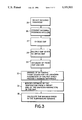
- FIG. 3 is a flow-chart, demonstrating the steps by which this invention determines the estimate of the temperature along with the largest possible error in the temperature determination.
- the preferred embodiment contains two devices: a detector and a computer.
- the detector includes a spectrograph and a series of photodetectors.
- FIG. 1 The apparatus configuration of the preferred embodiment is represented in FIG. 1.
- a Photo-Research Spectra Scan PR-700 PC® or similar equipment is used as the spectrograph/detector (01). This device automatically filters out undesirable light and converts the incoming radiances into electronic radiance signals usable by the computer (02).
- FIG. 2 demonstrates the configuration of an alternative embodiment wherein the baffle/filter apparatus is operatively connected to a non-self-filtering spectrograph. Spectral radiance emissions emanate from the source object (10). These are then passed through limiting optical filters (11) and baffles (12) to scatter and eliminate undesirable wavelengths of light. A number of filters and baffles may be included and arranged in any order.
- the radiances then pass through focusing optics (13) of either reflective or refractive form.
- the focused beam then passes through dispersive optics (14). These can take the forms of either reflective optics (i.e., a spectrograph), or transmissive (i.e., narrow band filters).
- the beam may then be passed (though it is optional) through channeling optics (15) into the photodetector housing (16), inside of which are the photosensitive detectors.
- the photodetectors convert the radiances into electronic radiance signals, which are conveyed to the computer (17) for processing.
- FIG. 3 is a flow-chart describing the steps by which the preferred embodiment estimates the temperature of the source object from the spectral radiance it emits. Steps 25 and 26 are performed by the spectrograph in the preferred embodiment, and the baffle/filter apparatus in conjunction with the spectrograph in the alternate embodiment. Steps 27 through 32 are performed by the computer.
- an appropriate emissivity model function (EMF) must be chosen (27).
- this function may be supplied to the computer by the user, or the user may select the function from a bank of functions predetermined within the computer, or the computer itself may be programmed to select the function from the bank.
- RTR radiance/temperature relation
- the computer multiplies the EMF by the radiance/temperature relation (RTR), which for non-linear least-squares analysis is the Planck Radiance Formula, while for linear analysis the RTR is the Wien Approximation to the Plank Radiance Formula.
- RTR radiance/temperature relation
- the multiplication results in the Radiance/Wavelength Function (RWF) (28).
- the EMF has a functional form of dependence on the wavelength, with unknown parameters as coefficients.
- the EMF can assume many different forms. Examples of the form might be linear, exponential, quadratic, or a Fourier series in the wavelength. Since the wavelength values will be known by the computer, effectively it is these unknown parameters which are the unknown variables in the function. Thus, for the EMF
- N i is defined as the theoretical value of the radiance at the ith wavelength, as predicted by the radiance/wavelength function; ⁇ i is the value of the ith wavelength band; T is the temperature; the ⁇ 's are the unknown parameters; and C 1 and C 2 are the Planck Radiation constants.
- the computer then establishes a difference function (DF), formed as the difference between the RWF and the input ERS values from the detector (29): ##EQU1## where n is defined as the total number of wavelength bands at which measurements of the radiance of the object were taken; m is the total number of unknown parameters; f i is the measured value of the radiance at the ith wavelength band (i.e., the ERS corresponding to the ith wavelength); and d ⁇ i is the uncertainty in the value of the ith wavelength (i.e. the width of the band).
- DF difference function
- the computer After establishing the DF, the computer is programmed to curve-fit the RWF to the ERS by finding those values for the unknown parameters, ⁇ 0 , . . . , ⁇ m-1 , which minimize the DF (30). At this point, the user may have an option. If the EMF chosen was a linear exponential function of the wavelength, the user may opt for the faster, though less flexible, linear least-squares method of curve-fitting. Otherwise, the non-linear method is used. Both of these methods are now described.
- the linear least-squares method uses linear algebra techniques to solve for the values of the unknown parameters.
- the unknown parameters are the a i coefficients; because the equations are linear with respect to these parameters, we can derive the following equations.
- the overspecified system of equations is inconsistent and in general has no solution.
- One can get around this problem by defining an error function (E) and then minimizing it; more precisely, we will minimize the square root of the sum of the squares of the error.
- ⁇ n Smallest Singular Value of A.
- Equations (1) and (2) describe the effects of perturbations in the data B and the coefficient matrix A on the solution X.
- condition numbers can be thought of as amplification factors for the translation of a perturbation in B or A on to a perturbation in X LS .
- ⁇ is a measure of how closely the equations AX can match the data B.
- perturbations in B would arise from noise in the measured data.
- Perturbations in A would be caused primarily by roundoff error during the LS calculations and would not be very significant unless A was largely conditioned (i.e. had a very large condition number).
- the measured data (f i ) for Multiwavelength Pyrometry (assuming perfect measurements) is the product of two functions:
- the values of the unknown parameters X can be evaluated. As shown, the value for the temperature is inversely proportional to the value of ⁇ m-1 :
- the error is determined from the condition number and the closeness of fit as determined by ⁇ .
- the larger the condition number the more inaccurate the estimate of the temperature will be for a given noise level.
- the solution technique used here is described by Bevington.
- the algorithm used is termed the Gradient Expansion algorithm and was first presented by Marquardt. This algorithm searches the surface defined by ⁇ 2 over the m dimensions for a minimum. When ⁇ 2 is large this method follows the gradient of ⁇ 2 . As ⁇ 2 gets smaller, the algorithm linearizes ⁇ 2 by a Taylor expansion. Finally when ⁇ 2 is very small the algorithm does a linear fit to the data. How easy this task will be depends upon the shape of the surface defined by ⁇ 2 .
- This inequality describes an m dimensional ellipsoid for each value ⁇ of ⁇ 2 ( ⁇ ).
- the ellipsoid of interest covers a volume of uncertainty in the parameter space, i.e., we cannot determine any of the parameters with an error less than L multiplied by the smallest axis of the ellipsoid.
- the quantity L is a constant on the order of n 1/2 . We can predict L only in order of magnitude terms.
- the desired vector is an unnormalized eigenvector of H' with an eigenvalue ⁇ .
- Each one of these eigenvectors forms an axis of the ellipsoid, and so the worst error will lie in the direction corresponding to the eigenvector with the smallest eigenvalue.
- H' is a Hermitian matrix.
- Hermitian matrices have the property that the singular values are equal to the absolute value of the eigenvalues. Additionally the singular vectors are equal to the eigenvectors if the matrix is positive semidefinite, otherwise, the singular and eigenvectors agree to within a factor of (-1) 1/2 . So, we can write the equation as:
Abstract
An apparatus and method for non-contact temperature measurement of an object, using least-squares-based multiwavelength pyrometry techniques. Radiances from an object are detected by a spectrograph/detector apparatus and are converted into electronic signals readable by a computer. The computer then operates on these signals as data to be curve-fit, using least squares analysis, to a predetermined theoretical function for the dependence of the radiance on the wavelength. When the computer has minimized the least-squares difference function, the computer identified a parameter representing the temperature and reports this value to the user, along with a collaterally calculated maximum error in the temperature estimate.
Description
The Government has rights in this invention pursuant to Contract Number N00014-80-C-0384 awarded by the Office of Naval Research.
This is a continuation of copending application Ser. No. 07/320,888, filed on Mar. 9, 1989, now abandoned, which is a continuation-in-part of copending application Ser. No. 296,538, filed on Jan. 12, 1989, now abandoned.
This invention relates to non-contact temperature pyrometry, and more particularly to least-squares-based multiwavelength pyrometry techniques.
Pyrometric non-contact temperature measurement of high-temperature sources has been known for at least sixty years. Such measurement makes use of the Planck Radiance Formula:
N(λ)=ε(λ)C.sub.1 λ.sup.-5 [exp/(C.sub.2 /λT)-1].sup.-1
where:
N is the spectral radiance emission, ε(λ) is the emissivity of the material at wavelength λ, T is the temperature, and C1 and C2 are Planck radiation constants. Strictly speaking, many pyrometry techniques use the Wien Approximation to the Planck Radiance Formula, which is:
N(λ)=ε(λ)C.sub.1 λ.sup.-5 exp(-C.sub.2 /λT)
By measuring the spectral radiance emission, N, at a wavelength λ, and by supplying the appropriate values for ε, C1, and C2, an estimate of the temperature of the source can thus be calculated.
Historically there have been two distinct techniques for such calculations. The older technique is sometimes known as ratio pyrometry. This technique involves measurement of radiance emission at a number of different wavelengths in the attempt to eliminate the emissivity term by making ratios of the measured radiances. The other, newer, method of pyrometry is known as multiwavelength pyrometry. In this method, again, measurements of the spectral radiance emissions of the object are taken at several wavelengths. The processing of this data is then performed by a variety of techniques, the most accurate of which have proven to be least-squares-based multiwavelength techniques. These involve fitting the radiance emission data to an assumed emissivity functional form. Ratio techniques have not, in general, provided adequately accurate temperature estimates for broad industrial usage. The often large inaccuracies of the ratio techniques have been attributed to the fact that they require unrealistic assumptions to be made about the nature of the emissivity, ε, in the Planck formula. Ratio techniques assume that both (in the case of two-color) or certain (in the cases of three-color or four-color) of the emissivities at the measured wavelengths be equal. Multiwavelength, particularly a least-squares-based, techniques have been somewhat more successful, largely because they more reasonably assume a wavelength-dependent emissivity function, rather than that all or some of the emissivities are equal. In fact, with certain materials, these techniques have proven to be accurate to within one percent. With other materials, however, results have been unsatisfactory. It has been assumed by previous investigators that the unsatisfactory results have been due to two sources: first, incorrect form or lack of sufficient complexity of the assumed emissivity model function; and second, so-called "correlation effects" due to the inability of curve-fitting routines to distinguish in certain circumstances between changes in emissivity and changes in temperature.
A need has therefore been felt for a method and device which can yield an accurate estimate of the temperature of a source object, along with providing a determination of the largest possible error in the temperature estimate.
In response to this longfelt need, the applicant has developed an apparatus and method for non-contact temperature measurement of an object, using least-squares-based pyrometry techniques. The invention includes a detector and a computer.
The detector apparatus, in the preferred embodiment, includes a spectrograph which responds to incoming radiances from the object, and separates these incoming radiances into small wavelength bands. These bands are then converted into electronic radiance signals by photosensitive devices, one for each wavelength band. The photosensitive devices provide electronic radiance signals of strength corresponding to the intensity of the incoming radiances at their respective wavelength bands. In this embodiment, the spectrograph is internally calibrated to scatter or eliminate undesirable or extraneous incoming radiances.
In another embodiment, a baffle and filter apparatus, operatively connected to the spectrograph, is required to eliminate detection of undesirable stray light and undesirable wavelengths of light from the object.
The computer responds to the electronic radiance signals generated by the photosensitive devices of the spectrograph. The computer operates on the raw data (i.e. the electronic radiance signals), along with a predetermined emissivity model function, to generate an estimated value of the temperature of the object, along with an estimate of the largest possible error in the value for the temperature. In one embodiment, the emissivity model function is input directly by the user. In another embodiment, the emissivity model function is selected by the user from a bank of potential emissivity model functions included within the computer. In yet another embodiment, the computer itself selects the appropriate emissivity model function from a bank of potential emissivity model functions. The emissivity model function is a function which models the wavelength dependence of the emissivity for the material from which the object is made. The computer is adapted to first multiply the chosen emissivity model function by the Plank Radiance Formula (or the Wien Approximation thereto, in the case of linear techniques) in order to generate a radiance/wavelength function. This radiance/wavelength function constitutes a model for the theoretical dependence of the incoming radiance on the wavelength of detection. The computer then curve-fits the data (i.e. the electronic radiance signals) with the theoretical model, radiance/wavelength function. The object is to minimize the difference between the respective radiance values predicted by the radiance/wavelength function and those detected electronic radiance signals incoming from the object. The computer is adapted to generate a least-squares difference function, which is related to the difference between the detected electronic radiance signals and the respective radiance values predicted by the radiance/wavelength function. The computer is then programmed to minimize this difference function by finding values for the unknown parameters in the radiance/wavelength function which provide a minimum for the difference function. The computer is then programmed to identify an estimated value of the temperature from a preselected one of the unknown parameters of the radiance wavelength function. Lastly, the computer is programmed to calculate an estimate of the largest possible error in the value for the temperature from the now determined values of the unknown parameters in the radiance/wavelength function.
FIG. 1 is a schematic representation of the apparatus configuration of the preferred embodiment, wherein the self-filtering spectrograph/detector apparatus is shown connected to the computer.
FIG. 2 is a schematic representation of the baffle/filter apparatus, operatively connected to the detector, which comprises a spectrograph and a photodetector housing. The detector is further shown connected to the computer.
FIG. 3 is a flow-chart, demonstrating the steps by which this invention determines the estimate of the temperature along with the largest possible error in the temperature determination.
The preferred embodiment contains two devices: a detector and a computer. The detector, in turn, includes a spectrograph and a series of photodetectors.
The apparatus configuration of the preferred embodiment is represented in FIG. 1. A Photo-Research Spectra Scan PR-700 PC® or similar equipment is used as the spectrograph/detector (01). This device automatically filters out undesirable light and converts the incoming radiances into electronic radiance signals usable by the computer (02). FIG. 2 demonstrates the configuration of an alternative embodiment wherein the baffle/filter apparatus is operatively connected to a non-self-filtering spectrograph. Spectral radiance emissions emanate from the source object (10). These are then passed through limiting optical filters (11) and baffles (12) to scatter and eliminate undesirable wavelengths of light. A number of filters and baffles may be included and arranged in any order. The radiances then pass through focusing optics (13) of either reflective or refractive form. The focused beam then passes through dispersive optics (14). These can take the forms of either reflective optics (i.e., a spectrograph), or transmissive (i.e., narrow band filters). The beam may then be passed (though it is optional) through channeling optics (15) into the photodetector housing (16), inside of which are the photosensitive detectors. Lastly, the photodetectors convert the radiances into electronic radiance signals, which are conveyed to the computer (17) for processing.
FIG. 3 is a flow-chart describing the steps by which the preferred embodiment estimates the temperature of the source object from the spectral radiance it emits. Steps 25 and 26 are performed by the spectrograph in the preferred embodiment, and the baffle/filter apparatus in conjunction with the spectrograph in the alternate embodiment. Steps 27 through 32 are performed by the computer.
After the computer receives the electronic radiance signals (ERS), an appropriate emissivity model function (EMF) must be chosen (27). By the various embodiments, this function may be supplied to the computer by the user, or the user may select the function from a bank of functions predetermined within the computer, or the computer itself may be programmed to select the function from the bank. After the function has been chosen, the computer multiplies the EMF by the radiance/temperature relation (RTR), which for non-linear least-squares analysis is the Planck Radiance Formula, while for linear analysis the RTR is the Wien Approximation to the Plank Radiance Formula. The multiplication results in the Radiance/Wavelength Function (RWF) (28).
The EMF has a functional form of dependence on the wavelength, with unknown parameters as coefficients. The EMF can assume many different forms. Examples of the form might be linear, exponential, quadratic, or a Fourier series in the wavelength. Since the wavelength values will be known by the computer, effectively it is these unknown parameters which are the unknown variables in the function. Thus, for the EMF
EMF=ε(α.sub.0, α.sub.1, . . . , α.sub.m-1)
where ε is the emissivity, and the α's are the unknown parameters. This leads to
N.sub.i =ε(λ.sub.i, α.sub.0, α.sub.1, . . . , α.sub.m-1)C.sub.1 λ.sub.i.sup.-5 exp(-C.sub.2 /λ.sub.i T),
where Ni is defined as the theoretical value of the radiance at the ith wavelength, as predicted by the radiance/wavelength function; λi is the value of the ith wavelength band; T is the temperature; the α's are the unknown parameters; and C1 and C2 are the Planck Radiation constants.
The computer then establishes a difference function (DF), formed as the difference between the RWF and the input ERS values from the detector (29): ##EQU1## where n is defined as the total number of wavelength bands at which measurements of the radiance of the object were taken; m is the total number of unknown parameters; fi is the measured value of the radiance at the ith wavelength band (i.e., the ERS corresponding to the ith wavelength); and dλi is the uncertainty in the value of the ith wavelength (i.e. the width of the band).
After establishing the DF, the computer is programmed to curve-fit the RWF to the ERS by finding those values for the unknown parameters, α0, . . . ,αm-1, which minimize the DF (30). At this point, the user may have an option. If the EMF chosen was a linear exponential function of the wavelength, the user may opt for the faster, though less flexible, linear least-squares method of curve-fitting. Otherwise, the non-linear method is used. Both of these methods are now described.
The linear least-squares method uses linear algebra techniques to solve for the values of the unknown parameters. Consider the problem of fitting some data (b1,b2. . . ,bn) to a polynomial of degree m. If n>m, we say that the problem is "overdetermined". If, for example, n=3 and m=1 then we will have to solve the following system of equations
a.sub.0 +a.sub.1 Y.sub.1 =b.sub.1
a.sub.0 +a.sub.1 Y.sub.2 =b.sub.2
a.sub.0 +a.sub.1 Y.sub.3 =b.sub.3
Here, the unknown parameters are the ai coefficients; because the equations are linear with respect to these parameters, we can derive the following equations. The overspecified system of equations is inconsistent and in general has no solution. One can get around this problem by defining an error function (E) and then minimizing it; more precisely, we will minimize the square root of the sum of the squares of the error.
E=SQRT[(a.sub.0 +a.sub.1 Y.sub.1 -b.sub.1).sup.2 +(a.sub.0 +a.sub.1 Y.sub.2 -b.sub.2).sup.2 +(a.sub.0 +a.sub.1 Y.sub.3 -b.sub.3).sup.2 ]
or in matrix form: ##EQU2## The minimum of E2 will be found by solving the system of equations ##EQU3## and in matrix form:
A.sup.T AX-A.sup.T B=0
In general the method of Least Squares involves finding the minimum of ||AX-B||. Thus,
ρ=||AX-B||
and at the minimum
ρ.sub.LS =||AX.sub.LS -B||.
From trigonometry, we can define ##EQU4## Then it can be shown that in the worst case ##EQU5## where us (t) is called the "condition number" of t with respect to s, and ##EQU6## A+ =Pseudo-Inverse of A, σ1 =Largest Singular Value of A,
σn =Smallest Singular Value of A.
Equations (1) and (2) describe the effects of perturbations in the data B and the coefficient matrix A on the solution X. In the simplest terms the condition numbers can be thought of as amplification factors for the translation of a perturbation in B or A on to a perturbation in XLS. Whereas θ is a measure of how closely the equations AX can match the data B.
For the case being discussed here, perturbations in B would arise from noise in the measured data. Perturbations in A would be caused primarily by roundoff error during the LS calculations and would not be very significant unless A was terribly conditioned (i.e. had a very large condition number).
So far we have made no mention of the number of data points n that we are dealing with. In general the actual condition number for perturbations in the data is lower by an approximate multiple of n-1/2, i.e., ##EQU7## It should be kept in mind that this is only an order of magnitude approximation.
The measured data (fi) for Multiwavelength Pyrometry (assuming perfect measurements) is the product of two functions:
f.sub.i =ε(λ.sub.i)C.sub.1 λ.sub.i.sup.-5 [exp(C.sub.2 /λ.sub.i T)-1].sup.-1
where
λi =ith wavelength,
ε(λ)=Emissivity.
In general we do not know much about ε(λ), but we can make some simplifying assumptions:
i) ε(λ),ε'(λ),ε""(λ) are
continuous over some sufficiently small (λ1, λ2)
ii) ε(λ) is single valued over some
sufficiently small (λ1, λ2)
Given these assumptions we can approximate the emissivity with any suitable analytic function such as a polynomial in λ or an exponential raised to a polynomial in λ. This function f is to be modeled by a fitting function g. At this point, however, f is nonlinear in at least one of the unknowns, the temperature T. So we rearrange it, after making the Wien approximation, to get
ln(C.sub.1.sup.-1 f.sub.i λ.sub.i.sup.5)=lnε-C.sub.2 λ.sub.i.sup.-1 T.sup.-1
All the quantities on the left side of this equation are known and on the right side the unknowns are ε and temperature. If we define ##EQU8## the emissivity is then modeled by ##EQU9## and the unknown parameters are the m-1 coefficients (α0, α1, . . . , αm-2) of the m-2 degree polynomial and the temperature T. We now have g as a linear function of the unknown parameters.
Translating this into the terms used to describe the linear LS technique we get ##EQU10##
Using this method, the values of the unknown parameters X can be evaluated. As shown, the value for the temperature is inversely proportional to the value of αm-1 :
T=C.sub.2 /α.sub.m-1
The error is determined from the condition number and the closeness of fit as determined by θ. The larger the condition number, the more inaccurate the estimate of the temperature will be for a given noise level.
If the EMF is not a linear exponential function of the wavelength, non-linear least-squares methods are used. The technique is as follows.
Consider the case where one is trying to fit the data f with the function N. From the above ##EQU11##
One now wishes to evaluate the parameters αj at the minimum of χ2. If N is nonlinear in the αj, then the system of equations resulting from differentiating χ2 with respect to the αj will be nonlinear; and linear techniques such as Gaussian elimination, cannot be used to solve this system of equations. One would then have to look for some sort of iterative technique to locate the minimum in χ2.
The solution technique used here is described by Bevington. The algorithm used is termed the Gradient Expansion algorithm and was first presented by Marquardt. This algorithm searches the surface defined by χ2 over the m dimensions for a minimum. When χ2 is large this method follows the gradient of χ2. As χ2 gets smaller, the algorithm linearizes χ2 by a Taylor expansion. Finally when χ2 is very small the algorithm does a linear fit to the data. How easy this task will be depends upon the shape of the surface defined by χ2.
To study the behavior of χ2, we expand it in a Taylor Series around the minimum. We start by defining the following ##EQU12## J'=Gradient at β=β', H'=Hessian at β=β',
δβ=β-β'.
Assuming χ2 is quadratic in a sufficiently small neighborhood around β=β', then, expanding χ2 in a Taylor series, we can write
χ.sup.2 (β)˜χ.sup.2 (β')+J'.sup.T δβ+1/2δβ.sup.T H'δβ.
If β' is an unconstrained minimum and the function N is a reasonable model for the data f, then J=0 and χ2 (β')≈0 by definition. The above equation then reduces to
χ.sup.2 (β)≧1/2δβ.sup.T H'δβ.
This inequality describes an m dimensional ellipsoid for each value ν of χ2 (β). The ellipsoids are concentric and centered around δβ=0. The ellipsoid of interest covers a volume of uncertainty in the parameter space, i.e., we cannot determine any of the parameters with an error less than L multiplied by the smallest axis of the ellipsoid. The quantity L is a constant on the order of n1/2. We can predict L only in order of magnitude terms.
Our interest, however, is more in the magnitude of the largest possible error, i.e. we wish to locate the points on the ellipsoid farthest from the center. Thus we wish to find the vector δβ which maximizes
δβ.sup.T H'δβ=2ν.
It can be shown, using the method of Lagrange multipliers, that the desired vector is an unnormalized eigenvector of H' with an eigenvalue η. So,
δβ.sup.T δβ=2ν/η.
Each one of these eigenvectors forms an axis of the ellipsoid, and so the worst error will lie in the direction corresponding to the eigenvector with the smallest eigenvalue.
||δβ||=[2ν/η.sub.smallest ].sup.1/2
In general,
||δβ||≦[2ν/η.sub.smallest ].sup.1/2
and in particular
||δβ|| is of the order of [2ν/nη.sub.smallest ].sup.1/2.
If the data fi are measured with an uncertainty Δ1, then we can tolerate a change of ##EQU13## In χ2 without having any reason to prefer one value of δβ over another as long as they all lie in the region define by ##EQU14## This means that the m-dimensional ellipsoid described above is now defined by ##EQU15## rather than just by ν. So the error in the parameter estimation is now given by ##EQU16## In general, ##EQU17## and in particular,
||δβ|| is of the order of ##EQU18##
Eigenvalue calculations are difficult and sometimes unstable, so we wish to avoid them if possible. Fortunately, for the cases we deal with here, H' is a Hermitian matrix. Hermitian matrices have the property that the singular values are equal to the absolute value of the eigenvalues. Additionally the singular vectors are equal to the eigenvectors if the matrix is positive semidefinite, otherwise, the singular and eigenvectors agree to within a factor of (-1)1/2. So, we can write the equation as:
||δβ|| is of the order of ##EQU19## where σ.sub.smallest is the smallest singular value of H.
In the non-linear technique, the user is allowed to determine which of the unknown parameters contained in β is to serve as the parameter corresponding to the temperature estimate. In turn, the worst possible error, presented in percentage form is ##EQU20##
After the computer has determined the values for the temperature and error, these quantities are displayed to the user.
Other embodiments are within the following claims.
Claims (36)
1. Apparatus for non-contact temperature measurement of an object, comprising:
detector apparatus, responsive to radiances of the object at multiple wavelengths, to generate electronic radiance signals corresponding to the detected radiances at each of the multiple wavelengths; wherein the detector apparatus further comprises:
spectrograph apparatus, responsive to the incoming radiances from the object, adapted to separate the incoming radiances into small wavelength bands; and
photosensitive devices, one responsive to each of the wavelength bands, to convert incoming radiances into electronic radiance signals, each of the signals of strengths corresponding to the intensity of the incoming radiances at the respective multiple wavelength bands; and computing apparatus, responsive to the electronic radiance signals, the computing apparatus including at least one pre-selected emissivity model function, with unknown parameters, for the wavelength dependence of the emissivity of the object; wherein the computer apparatus is adapted to:
multiply the emissivity model function by a radiance/temperature relation to generate a radiance/wavelength function;
minimize a difference function, related to the difference between the detected electronic radiance signals and the respective radiance values predicted by the radiance/wavelength function, by finding the values for the unknown parameters in the radiance/wavelength function which minimize the difference function;
identify an estimated value of the temperature from a pre-determined one of the unknown parameters of the emissivity model function and radiance/wavelength function; and
calculate an estimate of the error in the temperature from now-determined values of the unknown parameters and the difference function, wherein a baffle and filter apparatus is operatively connected to the spectrograph apparatus, eliminating detection of undesirable stray light and undesirable stray wavelength bands of light.
2. Apparatus for non-contact temperature measurement of an object, comprising:
detector apparatus, responsive to radiances of the object at multiple wavelengths, to generate electronic radiance signals corresponding to the detected radiances at each of the multiple wavelengths; and computing apparatus, responsive to the electronic radiance signals, the computing apparatus including at least one pre-selected emissivity model function, with unknown parameters, for the wavelength dependence of the emissivity of the object; wherein the computer apparatus is adapted to:
multiply the emissivity model function by a radiance/temperature relation to generate a radiance/wavelength function;
minimize a difference function, related to the difference between the detected electronic radiance signals and the respective radiance values predicted by the radiance/wavelength function, by finding the values for the unknown parameters in the radiance/wavelength function which minimize the difference function;
identify an estimated value of the temperature from a pre-determined one of the unknown parameters of the emissivity model function and radiance/wavelength function; and
calculate an estimate of the error in the temperature from now-determined values of the unknown parameters and the difference function, wherein the computing apparatus is further adapted so that the pre-selected emissivity model function is input directly by a user.
3. Apparatus for non-contact temperature measurement of an object, comprising:
detector apparatus, responsive to radiances of the object at multiple wavelengths, to generate electronic radiance signals corresponding to the detected radiances at each of the multiple wavelengths; and computing apparatus, responsive to the electronic radiance signals, the computing apparatus including at least one pre-selected emissivity model function, with unknown parameters, for the wavelength dependence of the emissivity of the object; wherein the computer apparatus is adapted to:
multiply the emissivity model function by a radiance/temperature relation to generate a radiance/wavelength function;
minimize a difference function, related to the difference between the detected electronic radiance signals and the respective radiance values predicted by the radiance/wavelength function, by finding the values for the unknown parameters in the radiance/wavelength function which minimize the difference function:
identify an estimated value of the temperature from a pre-determined one of the unknown parameters of the emissivity model function and radiance/wavelength function; and
calculate an estimate of the error in the temperature from now-determined values of the unknown parameters and the difference function, wherein the computing apparatus is further adapted so that a user selects the pre-selected emissivity model function from a bank of potential emissivity model functions, included in the computing apparatus.
4. Apparatus for non-contact temperature measurement of an object, comprising:
detector apparatus, responsive to radiances of the object at multiple wavelengths, to generate electronic radiance signals corresponding to the detected radiances at each of the multiple wavelengths; and computing apparatus, responsive to the electronic radiance signals, the computing apparatus including at least one pre-selected emissivity model function, with unknown parameters, for the wavelength dependence of the emissivity of the object; wherein the computer apparatus is adapted to:
multiply the emissivity model function by a radiance/temperature relation to generate a radiance/wavelength function;
minimize a difference function, related to the difference between the detected electronic radiance signals and the respective radiance values predicted by the radiance/wavelength function, by finding the values for the unknown parameters in the radiance/wavelength function which minimize the difference function;
identify an estimated value of the temperature from a pre-determined one of the unknown parameters of the emissivity model function and radiance/wavelength function; and
calculate an estimate of the error in the temperature from now-determined values of the unknown parameters and the difference function, wherein the computing apparatus is further adapted to include a bank of potential emissivity model functions, and further adapted to select the appropriate emissivity model function from the bank.
5. Apparatus for non-contact temperature measurement of an object, comprising:
detector apparatus, responsive to radiances of the object at multiple wavelengths, to generate electronic radiance signals corresponding to the detected radiances at each of the multiple wavelengths; and computing apparatus, responsive to the electronic radiance signals, the computing apparatus including at least one pre-selected emissivity model function, with unknown parameters, for the wavelength dependence of the emissivity of the object; wherein the computer apparatus is adapted to:
multiply the emissivity model function by a radiance/temperature relation to generate a radiance/wavelength function;
minimize a difference function, related to the difference between the detected electronic radiance signals and the respective radiance values predicted by the radiance/wavelength function, by finding the values for the unknown parameters in the radiance/wavelength function which minimize the difference function;
identify an estimated value of the temperature from a pre-determined one of the unknown parameters of the emissivity model function and radiance/wavelength function; and
calculate an estimate of the error in the temperature from now-determined values of the unknown parameters and the difference function, wherein the radiance/temperature relation is the Planck Radiance Formula, and
wherein the computing apparatus is adapted so that the emissivity model function, ε(λ), is multiplied by the Planck Radiance Formula, which is:
N=C.sub.1 λ.sup.-5 [exp(C.sub.2 /λT)-1].sup.-1
where: N is defined as the radiance of a blackbody object,
λ is defined as the wavelength of emitted radiance,
T is defined as the absolute temperature of a blackbody object,
C1, C2 are defined as the Planck radiation constants; the multiplication to provide a formula for the radiance of a real body rather than a blackbody, this formula known as the radiance/wavelength function; hence,
N(λ)=ε(λ)C.sub.1 λ.sup.-5 [exp( C.sub.2 /λT)-1].sup.-1,
wherein N is now the radiance of a real body (i.e., the object); and
wherein the difference function is a least squares function, wherein the least squares function is: ##EQU21## where: n is defined as the total number of the multiple wavelengths at which the radiance of the object is measured;
fi is defined as the ith measurement of the radiance of the object (i=1, . . . , n);
Ni is defined as the theoretical value of the radiance at the ith wavelength, as predicted by the radiance/wavelength function;
dλi is defined as the uncertainty in the value of the ith wavelength.
6. Apparatus of claim 5, wherein the computing apparatus is further adapted to minimize the least squares function, χ2, by finding those values of unknown parameters, α0, . . . , αm-1, of the emissivity model function, ε(λ), and the radiance/wavelength function, such that ##EQU22## is a minimum.
7. Apparatus of claim 6, wherein the radiance/temperature relation is the Wien Approximation to the Planck Radiance Formula, and wherein the computing apparatus is adapted to minimize the least squares function, χ2, using linear least squares curve-fitting.
8. Apparatus of claim 6, wherein the computing apparatus is adapted to minimize the least squares function, χ2, using non-linear least squares curve fitting.
9. Apparatus of claim 7, wherein the value for the temperature is related inversely to the value of the last of the unknown parameters, αm-1, by the relation:
T=C.sub.2 /α.sub.m-1.
10. Apparatus of claim 8, wherein the temperature is related to one of the unknown parameters, as pre-selected, the relation depending upon the particular one of the unknown parameters pre-selected, and the form of the non-linear emissivity model function chosen.
11. Apparatus of claims 9 or 10, wherein the computer apparatus is further adapted to determine an estimate of the error in the value for the temperature, the estimate of error relating to the differences between true and estimated values of the temperature and the other unknown parameters.
12. A method for non-contact temperature measurement of an object, comprising:
detection of radiances of the object to generate electronic radiance signals corresponding to the detected radiances at each of the multiple wavelengths; wherein the detection of the radiances is accomplished by a detector apparatus, comprising,
separating the incoming radiances into suitably small wavelength bands using a spectrograph apparatus responsive to the incoming radiances from the object; and
converting the incoming radiances from the spectrograph apparatus, using photodiode devices for each wavelength band, into electronic radiant signals, each of the signals of strengths corresponding to the intensity of the incoming radiances at the respective multiple wavelength bands;
and operating on the electronic radiance signals, using a computing apparatus, the computing apparatus adapted to include at least one pre-selected emissivity model function, with unknown parameters, for the wavelength dependence of the emissivity of the object, the operations comprising:
multiplication of the emissivity model function by a radiance/temperature relation to generate a radiance/wavelength function; minimization of a difference function, related to the difference between the detected electronic radiance signals and the respective radiance values predicted by the radiance/wavelength function, by finding the values for the unknown parameters in the radiance/wavelength function which minimize the difference function;
identification of an estimated value of the temperature from a pre-determined one of the unknown parameters of the emissivity model function and the radiance/wavelength function; and
calculation of an estimate of the error in the temperature from now-determined values of the unknown parameters and the difference function, wherein the detection of the incoming radiances is further aided by a baffle and filter apparatus, operatively connected to the spectrograph apparatus, to eliminate detection of undesirable stray light and undesirable stray wavelength bands of light.
13. A method for non-contact temperature measurement of an object, comprising:
detection of radiances of the object to generate electronic radiance signals corresponding to the detected radiances at each of the multiple wavelengths;
and operating on the electronic radiance signals, using a computing apparatus, the computing apparatus adapted to include at least one pre-selected emissivity model function, with unknown parameters, for the wavelength dependence of the emissivity of the object, the operations comprising:
multiplication of the emissivity model function by a radiance/temperature relation to generate a radiance/wavelength function; minimization of a difference function, related to the difference between the detected electronic radiance signals and the respective radiance values predicted by the radiance/wavelength function, by finding the values for the unknown parameters in the radiance/wavelength function which minimize the difference function;
identification of an estimated value of the temperature from a pre-determined one of the unknown parameters of the emissivity model function and the radiance/wavelength function; and
calculation of an estimate of the error in the temperature from now-determined values of the unknown parameters and the difference function, wherein the operating on the electronic radiance signals is facilitated by adapting the computing apparatus so that the pre-selected emissivity model function is input directly by a user.
14. A method for non-contact temperature measurement of an object, comprising:
detection of radiances of the object to generate electronic radiance signals corresponding to the detected radiances at each of the multiple wavelengths;
and operating on the electronic radiance signals, using a computing apparatus, the computing apparatus adapted to include at least one pre-selected emissivity model function, with unknown parameters, for the wavelength dependence of the emissivity of the object, the operations comprising:
multiplication of the emissivity model function by a radiance/temperature relation to generate a radiance/wavelength function; minimization of a difference function, related to the difference between the detected electronic radiance signals and the respective radiance values predicted by the radiance/wavelength function, by finding the values for the unknown parameters in the radiance/wavelength function which minimize the difference function;
identification of an estimated value of the temperature from a pre-determined one of the unknown parameters of the emissivity model function and the radiance/wavelength function; and
calculation of an estimate of the error in the temperature from now-determined values of the unknown parameters and the difference function, wherein operating on the electronic radiance signals is facilitated by the computer apparatus being adapted so as to include a bank of potential emissivity model functions, from which a user selects the pre-selected emissivity model function to be used by the computing apparatus.
15. A method for non-contact temperature measurement of an object, comprising:
detection of radiances of the object to generate electronic radiance signals corresponding to the detected radiances at each of the multiple wavelengths;
and operating on the electronic radiance signals, using a computing apparatus, the computing apparatus adapted to include at least one pre-selected emissivity model function, with unknown parameters, for the wavelength dependence of the emissivity of the object, the operations comprising:
multiplication of the emissivity model function by a radiance/temperature relation to generate a radiance/wavelength function;
minimization of a difference function, related to the difference between the detected electronic radiance signals and the respective radiance values predicted by the radiance/wavelength function, by finding the values for the unknown parameters in the radiance/wavelength function which minimize the difference function;
identification of an estimated value of the temperature from a pre-determined one of the unknown parameters of the emissivity model function and the radiance/wavelength function; and
calculation of an estimate of the error in the temperature from now-determined values of the unknown parameters and the difference function, wherein operating on the electronic radiance signals is facilitated by the computer apparatus being adapted to include a bank of potential emissivity model functions, the computer apparatus further adapted to select the appropriate emissivity model function from the bank.
16. A method for non-contact temperature measurement of an object, comprising:
detection of radiances of the object to generate electronic radiance signals corresponding to the detected radiances at each of the multiple wavelengths;
and operating on the electronic radiance signals, using a computing apparatus, the computing apparatus adapted to include at least one pre-selected emissivity model function, with unknown parameters, for the wavelength dependence of the emissivity of the object, the operations comprising:
multiplication of the emissivity model function by a radiance/temperature relation to generate a radiance/wavelength function;
minimization of a difference function, related to the difference between the detected electronic radiance signals and the respective radiance values predicted by the radiance/wavelength function, by finding the values for the unknown parameters in the radiance/wavelength function which minimize the difference function;
identification of an estimated value of the temperature from a pre-determined one of the unknown parameters of the emissivity model function and the radiance/wavelength function; and
calculation of an estimate of the error in the temperature from now-determined values of the unknown parameters and the difference function, wherein the radiance/temperature relation is the Planck Radiance Formula, and
wherein the computing apparatus is adapted to multiply the emissivity model function, ε(λ), by the Planck Radiance Formula, which is:
N=C.sub.1 λ.sup.-5 [exp( C.sub.2 /λT)-1].sup.-1
where:
N is defined as the radiance of a blackbody object,
λ is defined as the wavelength of emitted radiance,
T is defined as the absolute temperature of a blackbody object,
C1, C2 are defined as the Planck radiation constants; the multiplication to provide a formula for the radiance of a real body rather than a blackbody, this formula known as the radiance/wavelength function; hence,
N(λ)=ε(λ)C.sub.1 λ.sup.-5 [exp( C.sub.2 /λT)-1].sup.-1
where N is now the radiance of a real body (i.e., the object); and wherein the difference function is a least squares function,
wherein the least squares function is: ##EQU23## where: n is defined as the total number of the multiple wavelengths at which the radiance of the object is measured;
fi is defined as the ith measurement of the radiance of the object (i=1, . . . , n);
Ni is defined as the theoretical value of the radiance at the ith wavelength, as predicted by the radiance/wavelength function;
dλi is defined as the uncertainty in the value of the ith wavelength.
17. Method of claim 16, wherein the computing apparatus is further adapted to minimize the least squares function, χ2, by finding those values of unknown parameters, α0, . . . , αm-1, of the emissivity model function, ε(λ), and the radiance/wavelength function, such that ##EQU24## is a minimum.
18. Method of claim 17, wherein the radiance/temperature relation is the Wien Approximation to the Planck Radiance Formula, and wherein the computing apparatus is adapted to minimize the least squares function, χ2, using linear least squares curve-fitting.
19. Method of claim 17, wherein the computing apparatus is adapted to minimize the least squares function, χ2, using non-linear least squares curve fitting.
20. Method of claim 18, wherein the value for the temperature is related inversely to the value of the last of the unknown parameters, αm-1, by the relation:
T=C.sub.2 /α.sub.m-1.
21. Method of claim 19, wherein the temperature is related to one of the unknown parameters, as pre-selected, the relation depending upon the particular one of the unknown parameters pre-selected, and the form of the non-linear emissivity model function chosen.
22. Method of claims 20 or 21, wherein the computing apparatus is further adapted to determine an estimate of the error in the value for the temperature, the estimate of error relating to the differences between true and estimated values of the temperature and the other unknown parameters.
23. Apparatus for non-contact temperature measurement of an object, comprising:
detector apparatus, responsive to radiances of the object at multiple wavelengths, to generate electronic radiance signals corresponding to the detected radiances at each of the multiple wavelengths; and computing apparatus, responsive to the electronic radiance signals, the computing apparatus including at least one pre-selected emissivity model function, with unknown parameters, for the wavelength dependence of the emissivity of the object; wherein the computer apparatus is adapted to:
multiply the emissivity model function by a radiance/temperature relation to generate a radiance/wavelength function;
minimize a difference function, related to the difference between the detected electronic radiance signals and the respective radiance values predicted by the radiance/wavelength function, by finding the values for the unknown parameters in the radiance/wavelength function which minimize the difference function;
identify an estimated value of the temperature from a pre-determined one of the unknown parameters of the emissivity model function and radiance/wavelength function; and
calculate an estimate of the error in the temperature from now-determined values of the unknown parameters and the difference function, wherein the radiance/temperature relation is the Wien Approximation to the Planck Radiance Formula, and wherein the computing apparatus is adapted so that the emissivity model function, ε(λ), is multiplied by the Wien Approximation to the Planck Radiance Formula, which is: ##EQU25## where: N is defined as the radiance of a blackbody object,
λ is defined as the wavelength of emitted radiance,
T is defined as the absolute temperature of a blackbody object,
C1, C2 are defined as the Planck radiation constants; the multiplication to provide a formula for the radiance of a real body rather than a blackbody, this formula known as the radiance/wavelength function; hence,
N(λ)=ε(λ)C.sub.1 λ.sup.-5 exp( C.sub.2 /λT)
where N is now the radiance of a real body (i.e., the object); and
wherein the difference function is a least squares function,
wherein the least squares function is: ##EQU26## where: n is defined as the total number of the multiple wavelengths at which the radiance of the object is measured,
fi is defined as the ith measurement of the radiance of the object (i=1, . . . , n);
Ni is defined as the theoretical value of the radiance at the ith wavelength, as predicted by the radiance/wavelength function;
dλi is defined as the uncertainty in the value of the ith wavelength.
24. Apparatus of claim 23, wherein the computing apparatus is further adapted to minimize the least squares function, χ2, by finding those values of unknown parameters, α0, . . . , αm-1, of the emissivity model function, ε(λ), and the radiance/wavelength function, such that ##EQU27## is a minimum.
25. Apparatus of claim 24, wherein the computing apparatus is adapted to minimize the least squares function, χ2, using linear least squares curve-fitting.
26. Apparatus of claim 24, wherein the radiance/temperature relation is the Planck Radiance Formula, and wherein the computing apparatus is adapted to minimize the least squares function, χ2, using non-linear least squares curve fitting.
27. Apparatus of claim 25, wherein the value for the temperature is related inversely to the value of the last of the unknown parameters, αm-1, by the relation: T=C2 /αm-1.
28. Apparatus of claim 26, wherein the temperature is related to one of the unknown parameters, as pre-selected, the relation depending upon the particular one of the unknown parameters pre-selected, and the form of the non-linear emissivity model function chosen.
29. Apparatus of claims 27 or 28, wherein the computer apparatus is further adapted to determine an estimate of the error in the value for the temperature, the estimate of error relating to the differences between true and estimated values of the temperature and the other unknown parameters.
30. A method for non-contact temperature measurement of an object, comprising:
detection of radiances of the object to generate electronic radiance signals corresponding to the detected radiances at each of the multiple wavelengths;
and operating on the electronic radiance signals, using a computing apparatus, the computing apparatus adapted to include at least one pre-selected emissivity model function, with unknown parameters, for the wavelength dependence of the emissivity of the object, the operations comprising:
multiplication of the emissivity model function by a radiance/temperature relation to generate a radiance/wavelength function;
minimization of a difference function, related to the difference between the detected electronic radiance signals and the respective radiance values predicted by the radiance/wavelength function, by finding the values for the unknown parameters in the radiance/wavelength function which minimize the difference function;
identification of an estimated value of the temperature from a pre-determined one of the unknown parameters of the emissivity model function and the radiance/wavelength function; and
calculation of an estimate of the error in the temperature from now-determined values of the unknown parameters and the difference function; wherein the radiance/temperature relation is the Wien Approximation to the Planck Radiance Formula, and
wherein the computing apparatus is adapted to multiply the emissivity model function, ε(λ), by the Wien Approximation to the Planck Radiance Formula, which is: ##EQU28## where: N is defined as the radiance of a blackbody object,
λ is defined as the wavelength of emitted radiance,
T is defined as the absolute temperature of a blackbody object,
C1, C2 are defined as the Planck radiation constants; the multiplication to provide a formula for the radiance of a real body rather than a blackbody, this formula known as the radiance/wavelength function; hence,
N(λ)=ε(λ)C.sub.1 λ.sup.-5 exp(-(-C.sub.2 /λT),
where N is now the radiance of a real body (i.e., the object); and
wherein the difference function is a least squares function,
wherein the least squares function is: ##EQU29## where: n is defined as the total number of the multiple wavelengths at which the radiance of the object is measured;
fi is defined as the ith measurement of the radiance of the object (i=1, . . . , n);
Ni is defined as the theoretical value of the radiance at the ith wavelength, as predicted by the radiance/wavelength function;
dλi is defined as the uncertainty in the value of the ith wavelength.
31. Method of claim 30, wherein the computing apparatus is further adapted to minimize the least squares function, χ2, by finding those values of unknown parameters, α0, . . . , αm-1, of the emissivity model function, ε(λ), and the radiance/wavelength function, such that ##EQU30## is a minimum.
32. Method of claim 31, wherein the computing apparatus is adapted to minimize the least squares function, χ2, using linear least squares curve-fitting.
33. Method of claim 31, wherein the radiance/temperature relation is the Planck Radiance Formula, and wherein the computing apparatus is adapted to minimize the least squares function, χ2, using non-linear least squares curve fitting.
34. Method of claim 32, wherein the value for the temperature is related inversely to the value of the last of the unknown parameters, αm-1, by the relation:
T=C.sub.2 /α.sub.m-1.
35. Method of claim 33, wherein the temperature is related to one of the unknown parameters, as pre-selected, the relation depending upon the particular one of the unknown parameters pre-selected, and the form of the non-linear emissivity model function chosen.
36. Method of claim 34 or 35, wherein the computing apparatus is further adapted to determine an estimate of the error in the value for the temperature, the estimate of error relating to the differences between true and estimated values of the temperature and the other unknown parameters.
Applications Claiming Priority (2)
| Application Number | Priority Date | Filing Date | Title |
|---|---|---|---|
| US29653889A | 1989-01-12 | 1989-01-12 | |
| US32088889A | 1989-03-09 | 1989-03-09 |
Related Parent Applications (1)
| Application Number | Title | Priority Date | Filing Date |
|---|---|---|---|
| US32088889A Continuation | 1989-01-12 | 1989-03-09 |
Publications (1)
| Publication Number | Publication Date |
|---|---|
| US5132922A true US5132922A (en) | 1992-07-21 |
Family
ID=26969700
Family Applications (1)
| Application Number | Title | Priority Date | Filing Date |
|---|---|---|---|
| US07/673,261 Expired - Fee Related US5132922A (en) | 1989-01-12 | 1991-03-20 | Emissivity independent multiwavelength pyrometer |
Country Status (1)
| Country | Link |
|---|---|
| US (1) | US5132922A (en) |
Cited By (26)
| Publication number | Priority date | Publication date | Assignee | Title |
|---|---|---|---|---|
| US5326172A (en) * | 1992-12-14 | 1994-07-05 | The United States Of America As Represented By The Administrator Of The National Aeronautics And Space Administration | Multiwavelength pyrometer for gray and non-gray surfaces in the presence of interfering radiation |
| US5377126A (en) * | 1991-09-13 | 1994-12-27 | Massachusetts Institute Of Technology | Non-contact temperature measurement of a film growing on a substrate |
| EP0651235A1 (en) * | 1993-10-27 | 1995-05-03 | European Atomic Energy Community (Euratom) | A method for evaluating the channel signals of a multichannel pyrometer |
| US5690430A (en) * | 1996-03-15 | 1997-11-25 | Bethlehem Steel Corporation | Apparatus and method for measuring temperature and/or emissivity of steel strip during a coating process |
| US5772323A (en) * | 1994-10-26 | 1998-06-30 | Felice; Ralph A. | Temperature determining device and process |
| US5822222A (en) * | 1995-04-05 | 1998-10-13 | New Jersey Institute Of Technology | Multi-wavelength imaging pyrometer |
| DE19721475A1 (en) * | 1997-05-23 | 1998-11-26 | Eko Stahl Gmbh | Process for non-contact temperature measurement |
| EP0700214A3 (en) * | 1994-08-30 | 1999-01-07 | Hughes Electronics Corporation | Two stage video compression method and system |
| US5868496A (en) * | 1994-06-28 | 1999-02-09 | Massachusetts Institute Of Technology | Non-contact surface temperature, emissivity, and area estimation |
| US6222454B1 (en) | 1999-07-01 | 2001-04-24 | Goal Electronics Inc. | Non-contacting temperature sensing device |
| US6299346B1 (en) * | 1999-03-08 | 2001-10-09 | C. I. Systems Ltd | Active pyrometry with emissivity extrapolation and compensation |
| US20030151747A1 (en) * | 2002-01-15 | 2003-08-14 | Council Of Scientific And Industrial Research | Method for determining the reflectance profile of materials |
| US6738724B2 (en) | 2002-06-04 | 2004-05-18 | Mcintosh Devon R. | Two-stage multiwavelength thermal radiation analyzer |
| US6837617B1 (en) * | 1997-11-20 | 2005-01-04 | Israel Aircraft Industries Ltd. | Detection and recognition of objects by multispectral sensing |
| DE102005018124B4 (en) * | 2005-04-20 | 2007-06-28 | Barke, Woldemar, Dipl.-Phys. Ing. | Method and device for non-contact simultaneous determination of temperature and emissivity of a test object |
| US20070290131A1 (en) * | 2006-05-22 | 2007-12-20 | General Electric Company | Multiwavelength pyrometry systems |
| US20080310688A1 (en) * | 2005-02-25 | 2008-12-18 | Youfinder Intellectual Property Licensing Limited | Automated Indexing for Distributing Event Photography |
| US7561723B2 (en) | 2003-02-06 | 2009-07-14 | Youfinder Intellectual Property Licensing Limited Liability Company | Obtaining person-specific images in a public venue |
| US20100246631A1 (en) * | 2009-03-24 | 2010-09-30 | K-Space Associates, Inc. | Blackbody fitting for temperature determination |
| US20110128989A1 (en) * | 2009-11-30 | 2011-06-02 | General Electric Company | Multiwavelength thermometer |
| US8332281B2 (en) | 2009-09-02 | 2012-12-11 | Image Holdings | Method of displaying, managing and selling images in an event photography environment |
| US8392268B2 (en) | 2009-09-02 | 2013-03-05 | Image Holdings | Method and system of displaying, managing and selling images in an event photography environment |
| CN103281031A (en) * | 2013-06-17 | 2013-09-04 | 华北电力大学 | Squirrel cage asynchronous motor equivalent circuit parameter identification method based on measurable electrical capacity |
| WO2015161727A1 (en) * | 2014-04-25 | 2015-10-29 | 天津送变电易通电力科技有限公司 | Method for measuring actual temperature of flame using all information about radiation spectrum and measurement system |
| JP2020501149A (en) * | 2016-12-07 | 2020-01-16 | ユリス | Infrared image sensor |
| US11219729B2 (en) | 2018-03-21 | 2022-01-11 | Hansa Medical Products, Inc. | Medical device system and method including an endotracheal tube |
Citations (6)
| Publication number | Priority date | Publication date | Assignee | Title |
|---|---|---|---|---|
| US4411519A (en) * | 1979-08-28 | 1983-10-25 | Ishikawajima-Harima Heavy Industries Co., Ltd. | Method of and system for measuring temperature and spectral factor |
| US4652755A (en) * | 1985-01-10 | 1987-03-24 | Advanced Fuel Research, Inc. | Method and apparatus for analyzing particle-containing gaseous suspensions |
| US4746798A (en) * | 1986-08-18 | 1988-05-24 | Werkzeugmaschinenfabrik | Compact optical wavelength discriminator radiometer |
| US4880314A (en) * | 1985-07-30 | 1989-11-14 | Veb Messgeraetewerk "Erich Weinert" Magdeburg, Betrieb Des Kombinates Veb Eaw Berlin-Treptow | Pyrometric measurement procedure and multi-channel pyrometer |
| US4881823A (en) * | 1988-03-29 | 1989-11-21 | Purdue Research Foundation | Radiation thermometry |
| US4924478A (en) * | 1983-06-16 | 1990-05-08 | Deutsche Forschungs- Und Versuchsanstalt Fur Luft- Und Raumfahrt E.V. | Method of and device for contactless temperature measurement of an object independently of radiation emissivity |
-
1991
- 1991-03-20 US US07/673,261 patent/US5132922A/en not_active Expired - Fee Related
Patent Citations (6)
| Publication number | Priority date | Publication date | Assignee | Title |
|---|---|---|---|---|
| US4411519A (en) * | 1979-08-28 | 1983-10-25 | Ishikawajima-Harima Heavy Industries Co., Ltd. | Method of and system for measuring temperature and spectral factor |
| US4924478A (en) * | 1983-06-16 | 1990-05-08 | Deutsche Forschungs- Und Versuchsanstalt Fur Luft- Und Raumfahrt E.V. | Method of and device for contactless temperature measurement of an object independently of radiation emissivity |
| US4652755A (en) * | 1985-01-10 | 1987-03-24 | Advanced Fuel Research, Inc. | Method and apparatus for analyzing particle-containing gaseous suspensions |
| US4880314A (en) * | 1985-07-30 | 1989-11-14 | Veb Messgeraetewerk "Erich Weinert" Magdeburg, Betrieb Des Kombinates Veb Eaw Berlin-Treptow | Pyrometric measurement procedure and multi-channel pyrometer |
| US4746798A (en) * | 1986-08-18 | 1988-05-24 | Werkzeugmaschinenfabrik | Compact optical wavelength discriminator radiometer |
| US4881823A (en) * | 1988-03-29 | 1989-11-21 | Purdue Research Foundation | Radiation thermometry |
Non-Patent Citations (30)
| Title |
|---|
| D. Ya. Svet, High Temperatue High Pressure, 4 (6), Jun. 1972 pp. 715 722. * |
| D. Ya. Svet, High Temperatue-High Pressure, 4 (6), Jun. 1972 pp. 715-722. |
| D. Ya. Svet, Independent determination of emissivity from natural thermal radiation spectra, Sov. Phys. Dokl., vol. 20, No. 3, pp. 214 215 Mar. (1975). * |
| D. Ya. Svet, Independent determination of emissivity from natural thermal radiation spectra, Sov. Phys. Dokl., vol. 20, No. 3, pp. 214-215 Mar. (1975). |
| D. Ya. Svet, Sov. Phys. Dok1, 21 (3), Mar. 1976, pp. 162 163. * |
| D. Ya. Svet, Sov. Phys. Dok1, 21 (3), Mar. 1976, pp. 162-163. |
| G. B. Hunter, C. D. Allemand, T. W. Eagar, Opt. Eng., 24 (6), in press Nov./Dec. 1985, pp. 1081 1085. * |
| G. B. Hunter, C. D. Allemand, T. W. Eagar, Opt. Eng., 24 (6), in press Nov./Dec. 1985, pp. 1081-1085. |
| G. B. Hunter, C. D. Allemand, T. W. Eagar, Opt. Eng., 25 (11), Nov. 1986, pp. 1222 1231. * |
| G. B. Hunter, C. D. Allemand, T. W. Eagar, Opt. Eng., 25 (11), Nov. 1986, pp. 1222-1231. |
| J. H. Taylor; Planck s radiation law; Feb. 1987. * |
| J. H. Taylor; Planck's radiation law; Feb. 1987. |
| J. L. Gardner, High Temperatures High Pressures, 12, Dec. 1980, pp. 699 705. * |
| J. L. Gardner, High Temperatures-High Pressures, 12, Dec. 1980, pp. 699-705. |
| J. L. Gardner, T. P. Jones, M. R. Davies, A Broadband Ratiopyrometer, 5, 1982, pp. 409 412. * |
| J. L. Gardner, T. P. Jones, M. R. Davies, A Broadband Ratiopyrometer, 5, 1982, pp. 409-412. |
| J. L. Gardner, T. P. Jones, M. R. Davies, High Temperatures High Pressures, 13, Jul. 1981, pp. 459 466. * |
| J. L. Gardner, T. P. Jones, M. R. Davies, High Temperatures-High Pressures, 13, Jul. 1981, pp. 459-466. |
| J. P. Hiernaut, R. Beukers, M. Hoch, T. Matsui, R. W. Ohse, High Temperatures High Pressures, 18, Sep. 1986, pp. 627 633. * |
| J. P. Hiernaut, R. Beukers, M. Hoch, T. Matsui, R. W. Ohse, High Temperatures-High Pressures, 18, Sep. 1986, pp. 627-633. |
| J. P. Hiernaut, R. Beukers, W. Heinz, R. Selfsag, M. Hoch, R. W. Ohse, High Temperatures High Pressures, 18, Sep. 1986, pp. 617 625. * |
| J. P. Hiernaut, R. Beukers, W. Heinz, R. Selfsag, M. Hoch, R. W. Ohse, High Temperatures-High Pressures, 18, Sep. 1986, pp. 617-625. |
| M. A. Khan, Non Contact Temperature Measurement, Sc.D. Thesis, M.I.T., Cambridge, Mass. (Apr. 29, 1988). * |
| M. A. Khan, Non-Contact Temperature Measurement, Sc.D. Thesis, M.I.T., Cambridge, Mass. (Apr. 29, 1988). |
| P. B. Coates, Metrologia, 17 (3), Mar. 1981, pp. 103 109. * |
| P. B. Coates, Metrologia, 17 (3), Mar. 1981, pp. 103-109. |
| P. M. Reynolds, Brit. J. Appl. Phys., 15, 1964, pp. 579 589. * |
| P. M. Reynolds, Brit. J. Appl. Phys., 15, 1964, pp. 579-589. |
| P. R. Bevington, Data Reduction and Error Analysis for the Physical Sciences, pp. 134 232, McGraw Hill, N.Y., 1969. * |
| P. R. Bevington, Data Reduction and Error Analysis for the Physical Sciences, pp. 134-232, McGraw-Hill, N.Y., 1969. |
Cited By (35)
| Publication number | Priority date | Publication date | Assignee | Title |
|---|---|---|---|---|
| US5377126A (en) * | 1991-09-13 | 1994-12-27 | Massachusetts Institute Of Technology | Non-contact temperature measurement of a film growing on a substrate |
| US5326172A (en) * | 1992-12-14 | 1994-07-05 | The United States Of America As Represented By The Administrator Of The National Aeronautics And Space Administration | Multiwavelength pyrometer for gray and non-gray surfaces in the presence of interfering radiation |
| EP0651235A1 (en) * | 1993-10-27 | 1995-05-03 | European Atomic Energy Community (Euratom) | A method for evaluating the channel signals of a multichannel pyrometer |
| WO1995012114A1 (en) * | 1993-10-27 | 1995-05-04 | European Atomic Energy Community (Euratom) | A method for evaluating the channel signals of a multichannel pyrometer |
| US5868496A (en) * | 1994-06-28 | 1999-02-09 | Massachusetts Institute Of Technology | Non-contact surface temperature, emissivity, and area estimation |
| EP0700214A3 (en) * | 1994-08-30 | 1999-01-07 | Hughes Electronics Corporation | Two stage video compression method and system |
| US5772323A (en) * | 1994-10-26 | 1998-06-30 | Felice; Ralph A. | Temperature determining device and process |
| US5822222A (en) * | 1995-04-05 | 1998-10-13 | New Jersey Institute Of Technology | Multi-wavelength imaging pyrometer |
| US5690430A (en) * | 1996-03-15 | 1997-11-25 | Bethlehem Steel Corporation | Apparatus and method for measuring temperature and/or emissivity of steel strip during a coating process |
| DE19721475A1 (en) * | 1997-05-23 | 1998-11-26 | Eko Stahl Gmbh | Process for non-contact temperature measurement |
| US6837617B1 (en) * | 1997-11-20 | 2005-01-04 | Israel Aircraft Industries Ltd. | Detection and recognition of objects by multispectral sensing |
| US6299346B1 (en) * | 1999-03-08 | 2001-10-09 | C. I. Systems Ltd | Active pyrometry with emissivity extrapolation and compensation |
| US6222454B1 (en) | 1999-07-01 | 2001-04-24 | Goal Electronics Inc. | Non-contacting temperature sensing device |
| US20030151747A1 (en) * | 2002-01-15 | 2003-08-14 | Council Of Scientific And Industrial Research | Method for determining the reflectance profile of materials |
| US6963403B2 (en) * | 2002-01-15 | 2005-11-08 | Council Of Scientific And Industrial Research | Method for determining the reflectance profile of materials |
| US6738724B2 (en) | 2002-06-04 | 2004-05-18 | Mcintosh Devon R. | Two-stage multiwavelength thermal radiation analyzer |
| US7561723B2 (en) | 2003-02-06 | 2009-07-14 | Youfinder Intellectual Property Licensing Limited Liability Company | Obtaining person-specific images in a public venue |
| US8406481B2 (en) | 2005-02-25 | 2013-03-26 | Hysterical Sunset Limited | Automated indexing for distributing event photography |
| US8831275B2 (en) | 2005-02-25 | 2014-09-09 | Hysterical Sunset Limited | Automated indexing for distributing event photography |
| US20080310688A1 (en) * | 2005-02-25 | 2008-12-18 | Youfinder Intellectual Property Licensing Limited | Automated Indexing for Distributing Event Photography |
| DE102005018124B4 (en) * | 2005-04-20 | 2007-06-28 | Barke, Woldemar, Dipl.-Phys. Ing. | Method and device for non-contact simultaneous determination of temperature and emissivity of a test object |
| US20070290131A1 (en) * | 2006-05-22 | 2007-12-20 | General Electric Company | Multiwavelength pyrometry systems |
| US7633066B2 (en) | 2006-05-22 | 2009-12-15 | General Electric Company | Multiwavelength pyrometry systems |
| US8282273B2 (en) | 2009-03-24 | 2012-10-09 | K-Space Associates, Inc. | Blackbody fitting for temperature determination |
| US20100246631A1 (en) * | 2009-03-24 | 2010-09-30 | K-Space Associates, Inc. | Blackbody fitting for temperature determination |
| US8332281B2 (en) | 2009-09-02 | 2012-12-11 | Image Holdings | Method of displaying, managing and selling images in an event photography environment |
| US8392268B2 (en) | 2009-09-02 | 2013-03-05 | Image Holdings | Method and system of displaying, managing and selling images in an event photography environment |
| US20110128989A1 (en) * | 2009-11-30 | 2011-06-02 | General Electric Company | Multiwavelength thermometer |
| US8790006B2 (en) | 2009-11-30 | 2014-07-29 | General Electric Company | Multiwavelength thermometer |
| CN103281031A (en) * | 2013-06-17 | 2013-09-04 | 华北电力大学 | Squirrel cage asynchronous motor equivalent circuit parameter identification method based on measurable electrical capacity |
| WO2015161727A1 (en) * | 2014-04-25 | 2015-10-29 | 天津送变电易通电力科技有限公司 | Method for measuring actual temperature of flame using all information about radiation spectrum and measurement system |
| US11359967B2 (en) | 2014-04-25 | 2022-06-14 | Tianjin Yitong Transmission & Distribution Electric Technology Co. Ltd. | Method for measuring actual temperature of flame by using all information of radiation spectrum and measurement system thereof |
| JP2020501149A (en) * | 2016-12-07 | 2020-01-16 | ユリス | Infrared image sensor |
| JP2020513553A (en) * | 2016-12-07 | 2020-05-14 | ユリス | Infrared image sensor |
| US11219729B2 (en) | 2018-03-21 | 2022-01-11 | Hansa Medical Products, Inc. | Medical device system and method including an endotracheal tube |
Similar Documents
| Publication | Publication Date | Title |
|---|---|---|
| US5132922A (en) | Emissivity independent multiwavelength pyrometer | |
| Coates | Multi-wavelength pyrometry | |
| EP0156877B1 (en) | Multicomponent quantitative analytical method and apparatus | |
| EP0335224B1 (en) | Radiation thermometry | |
| US5098197A (en) | Optical Johnson noise thermometry | |
| US5868496A (en) | Non-contact surface temperature, emissivity, and area estimation | |
| US5249142A (en) | Indirect temperature-measurement of films formed on semiconductor wafers | |
| US5099121A (en) | Temperature measuring method using infrared sensors and processor | |
| SE8005998L (en) | PROCEDURE AND DEVICE FOR SEATING TEMPERATURE AND SPECTRAL FACTOR | |
| JPH02248822A (en) | Method and device for measuring temperature and emissivity of heat radiation substance | |
| US5690429A (en) | Method and apparatus for emissivity independent self-calibrating of a multiwavelength pyrometer | |
| RU2083961C1 (en) | Method of measurement of temperature and emissivity of surface | |
| US5326172A (en) | Multiwavelength pyrometer for gray and non-gray surfaces in the presence of interfering radiation | |
| US4952061A (en) | Method and apparatus for sensing or determining one or more properties or the identity of a sample | |
| US4605314A (en) | Spectral discrimination pyrometer | |
| Lindermeir et al. | Contactless measurement of the spectral emissivity and temperature of surfaces with a Fourier transform infrared spectrometer | |
| EP0651235B1 (en) | A method for evaluating the channel signals of a multichannel pyrometer | |
| Mazikowski et al. | Modeling of noncontact temperature measurement system using multiwavelength pyrometry | |
| JPH0815036A (en) | Method for correcting radiation thermometer and light measuring equipment by utilizing new interpolation formula | |
| Spitzberg | Parameter estimation for gray and nongray targets: theory and data analysis | |
| CN111562019B (en) | Multispectral radiation temperature measurement method and system | |
| Socas-Navarro | A simple procedure for optimizing the height resolution in spectral line inversions | |
| Chopko | Effective wavelength of a color pyrometer | |
| GB2113384A (en) | Contactless measurement of temperature | |
| SU888673A1 (en) | Method of measuring temperature |
Legal Events
| Date | Code | Title | Description |
|---|---|---|---|
| CC | Certificate of correction | ||
| FEPP | Fee payment procedure |
Free format text: PAYOR NUMBER ASSIGNED (ORIGINAL EVENT CODE: ASPN); ENTITY STATUS OF PATENT OWNER: SMALL ENTITY |
|
| FPAY | Fee payment |
Year of fee payment: 4 |
|
| SULP | Surcharge for late payment | ||
| REMI | Maintenance fee reminder mailed | ||
| LAPS | Lapse for failure to pay maintenance fees | ||
| FP | Lapsed due to failure to pay maintenance fee |
Effective date: 20000721 |
|
| STCH | Information on status: patent discontinuation |
Free format text: PATENT EXPIRED DUE TO NONPAYMENT OF MAINTENANCE FEES UNDER 37 CFR 1.362 |