US5127627A - Valve for an inflatable article - Google Patents
Valve for an inflatable article Download PDFInfo
- Publication number
- US5127627A US5127627A US07/711,445 US71144591A US5127627A US 5127627 A US5127627 A US 5127627A US 71144591 A US71144591 A US 71144591A US 5127627 A US5127627 A US 5127627A
- Authority
- US
- United States
- Prior art keywords
- channel
- valve
- fill tube
- sealing
- fill
- Prior art date
- Legal status (The legal status is an assumption and is not a legal conclusion. Google has not performed a legal analysis and makes no representation as to the accuracy of the status listed.)
- Expired - Fee Related
Links
Images

Classifications
-
- F—MECHANICAL ENGINEERING; LIGHTING; HEATING; WEAPONS; BLASTING
- F16—ENGINEERING ELEMENTS AND UNITS; GENERAL MEASURES FOR PRODUCING AND MAINTAINING EFFECTIVE FUNCTIONING OF MACHINES OR INSTALLATIONS; THERMAL INSULATION IN GENERAL
- F16K—VALVES; TAPS; COCKS; ACTUATING-FLOATS; DEVICES FOR VENTING OR AERATING
- F16K15/00—Check valves
- F16K15/20—Check valves specially designed for inflatable bodies, e.g. tyres
- F16K15/202—Check valves specially designed for inflatable bodies, e.g. tyres and with flexible valve member
Definitions
- the present invention relates to self-sealing valves, and in particular, it relates to self-sealing valves for use with inflatable articles.
- Valves affixed to the surface of inflatable articles are well known in the art. Such valves are designed to accommodate the passage therethrough of a fill tube which fill tube conducts a filling medium into the inflatable article. Such valves are described in, for example, U.S. Pat. Nos. 1,702,974; 2,700,980; 4,662,883; 3,410,300; and 4,930,535.
- a fill tube is typically inserted into the inflation chamber of an article through such a valve.
- the valve is typically made of two sheets of silicone rubber bonded together along their edges with a channel therebetween.
- Silicone gel is frequently used to either fill or partially fill the channel for two reasons. First, it is an excellent lubricant and facilitates the entry and passage of a fill tube through the channel. Second, if a fill tube is disposed within the valve for a long time, stresses in the silicone rubber forming the channel result in the valve not sealing adequately once the fill tube is removed. The channel becomes somewhat "set” in an open position and remains in the open position once the fill tube has been removed. To facilitate sealing of the valve channel once the fill tube is removed, a quantity of viscous gel is often disposed between the walls to partially fill the channel thereby to improve the sealing properties of the channel.
- valves of the type we are talking about here are the only entrance or exit of fluid from the interior of the article. It is also assumed that the article must be frequently inflated or deflated or the fill tube must be frequently reinserted and removed from the valve. Under such conditions, the sealing gel housed within the prior art valves is dislodged from the channel and either pushed into the article during insertion of the fill tube or pulled out of the valve during removal of the fill tube. To overcome these problems and provide a valve having the ability to retain a gel placed in the channel thereof even after multiple insertion of a fill tube, the present improved valve has been invented.
- An object of the improved valve of the present invention is to provide a fill valve for use with an inflatable article which valve retains a sealing gel placed in the channel thereof even after repeated insertions and withdrawals of a fill tube.
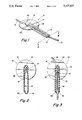
- FIG. 1 is a perspective view of the improved fill valve with the valve containing a fill tube.
- FIG. 2 is a horizontal sectional view taken on line 2--2 of FIG. 1 without the fill tube.
- FIG. 3 is as in FIG. 2 with the valve containing a fill tube.
- FIG. 4 is an organizational scheme of valve elements prior to forming and vulcanization.
- FIG. 5 is a perspective view of attachment of improved valve to the inner surface of a fluid-fillable chamber.
- FIG. 1 illustrates the valve of the present invention with a fill tube in place.
- the valve is used to provide a fill tube with access to the interior of a fluid-filled device.
- the valve is self-sealing to the track of a fill tube inserted therein and removed therefrom.
- the valve generally indicated at 10, includes a main body portion 11 having a channel 12 passing therethrough.
- a fill tube 13 is shown inserted to pass through the valve.
- the valve 10 has an interior end 14 which, in operation, extends into the inner chamber of the fluid-fillable device and serves as a seal when the fill tube 13 is removed from the device.
- FIG. 2 shows a cutaway view of the valve of FIG. 1 along line 2--2.
- the channel 12 has a constricted portion 2) which provides a means for retaining sealing gel (not shown) within the channel when the fill tube (not shown in FIG. 2) is withdrawn.
- the constriction 21 also provides a shoulder or stop for a fill tube wherein a portion of the length of the fill tube has an outer diameter greater than the diameter of the constricted portion (21) of the channel (12).
- the channel through the interior end 14 of the valve may be lengthened and have an inwardly tapered portion 22 which portion fits snugly against the walls of a fill tube passed therethrough in the manner of FIG. 3.
- a sealing gel would normally be housed within the channel in the region 31 between the constriction 21 and the tapered portion 22.
- an impermeable backing 43 FIG. 4
- the fill tube tends to push the gel before it.
- the valve is constructed by vulcanizing two sheets of pre-cut silicone rubber 41 and 42, one of which (42) is uncured, together in the manner shown.
- a third sheet of cured silicone 44, cut to the desired shape of the channel and an uncured dacron-reinforced silicone disc 43 are interposed therebetween prior to vulcanization. Since sheet 44 is pre-cured, it does not bond to sheet 41 thus forming a channel therebetween.
- the valve body 11 may be vulcanized to a receiving opening in a fluid-fillable device as shown in FIG. 5.
Landscapes
- Engineering & Computer Science (AREA)
- General Engineering & Computer Science (AREA)
- Mechanical Engineering (AREA)
- Check Valves (AREA)
Abstract
Description
Claims (1)
Priority Applications (1)
| Application Number | Priority Date | Filing Date | Title |
|---|---|---|---|
| US07/711,445 US5127627A (en) | 1991-06-06 | 1991-06-06 | Valve for an inflatable article |
Applications Claiming Priority (1)
| Application Number | Priority Date | Filing Date | Title |
|---|---|---|---|
| US07/711,445 US5127627A (en) | 1991-06-06 | 1991-06-06 | Valve for an inflatable article |
Publications (1)
| Publication Number | Publication Date |
|---|---|
| US5127627A true US5127627A (en) | 1992-07-07 |
Family
ID=24858120
Family Applications (1)
| Application Number | Title | Priority Date | Filing Date |
|---|---|---|---|
| US07/711,445 Expired - Fee Related US5127627A (en) | 1991-06-06 | 1991-06-06 | Valve for an inflatable article |
Country Status (1)
| Country | Link |
|---|---|
| US (1) | US5127627A (en) |
Cited By (14)
| Publication number | Priority date | Publication date | Assignee | Title |
|---|---|---|---|---|
| US5221264A (en) * | 1992-03-10 | 1993-06-22 | Wilk Peter J | Reduction port for laparoscopic trocar sleeve and related method |
| US5553829A (en) * | 1995-01-25 | 1996-09-10 | Honeywell Inc. | Solenoid valve with sound dampening feature |
| US5766222A (en) * | 1997-07-07 | 1998-06-16 | Petit; Michael G. | Nipple illuminator for photodynamic therapy |
| US5827227A (en) * | 1996-07-17 | 1998-10-27 | Delago; Augustin J. | Catheter having a radially adjustable sheath |
| EP0784310A3 (en) * | 1996-01-11 | 1999-07-14 | Guy Laufer | Amusement device |
| CN1072111C (en) * | 1995-02-09 | 2001-10-03 | 文森特德特洛兹 | Method and apparatus for providing at least one mark on the outer edge of a stack of pages |
| WO2005114015A1 (en) * | 2004-05-22 | 2005-12-01 | Venture One (Ip) Limited | Valve |
| US8821574B2 (en) * | 2012-12-05 | 2014-09-02 | Mentor Worldwide Llc | Valve assemblies for expandable implants and tissue expanders |
| US9387068B2 (en) | 2008-08-20 | 2016-07-12 | Allergan, Inc. | Self-sealing shell for inflatable prostheses |
| US10052190B2 (en) | 2010-02-05 | 2018-08-21 | Allergan, Inc. | Inflatable prostheses and methods of making same |
| USD896383S1 (en) | 2018-09-13 | 2020-09-15 | Allergan, Inc. | Tissue expansion device |
| US11160630B2 (en) | 2018-09-13 | 2021-11-02 | Allergan, Inc. | Tissue expansion device |
| US11413178B2 (en) * | 2016-08-10 | 2022-08-16 | Euromedical S.R.L. | Intragastric balloon and manufacturing method thereof |
| CN118415803A (en) * | 2024-07-05 | 2024-08-02 | 杭州糖吉医疗科技有限公司 | Integrated valve, intragastric balloon, preparation method thereof, and weight loss balloon set |
Citations (3)
| Publication number | Priority date | Publication date | Assignee | Title |
|---|---|---|---|---|
| US3410300A (en) * | 1966-10-14 | 1968-11-12 | Custom Materials Inc | Valve |
| US4662883A (en) * | 1985-07-17 | 1987-05-05 | Mentor Corporation | Self-sealing valve for fluid fillable device |
| US4930535A (en) * | 1987-05-14 | 1990-06-05 | Mcghan Medical Corporation | Folding leaf valve and method of making |
-
1991
- 1991-06-06 US US07/711,445 patent/US5127627A/en not_active Expired - Fee Related
Patent Citations (3)
| Publication number | Priority date | Publication date | Assignee | Title |
|---|---|---|---|---|
| US3410300A (en) * | 1966-10-14 | 1968-11-12 | Custom Materials Inc | Valve |
| US4662883A (en) * | 1985-07-17 | 1987-05-05 | Mentor Corporation | Self-sealing valve for fluid fillable device |
| US4930535A (en) * | 1987-05-14 | 1990-06-05 | Mcghan Medical Corporation | Folding leaf valve and method of making |
Cited By (18)
| Publication number | Priority date | Publication date | Assignee | Title |
|---|---|---|---|---|
| US5221264A (en) * | 1992-03-10 | 1993-06-22 | Wilk Peter J | Reduction port for laparoscopic trocar sleeve and related method |
| US5553829A (en) * | 1995-01-25 | 1996-09-10 | Honeywell Inc. | Solenoid valve with sound dampening feature |
| CN1072111C (en) * | 1995-02-09 | 2001-10-03 | 文森特德特洛兹 | Method and apparatus for providing at least one mark on the outer edge of a stack of pages |
| EP0784310A3 (en) * | 1996-01-11 | 1999-07-14 | Guy Laufer | Amusement device |
| US5827227A (en) * | 1996-07-17 | 1998-10-27 | Delago; Augustin J. | Catheter having a radially adjustable sheath |
| US5766222A (en) * | 1997-07-07 | 1998-06-16 | Petit; Michael G. | Nipple illuminator for photodynamic therapy |
| WO2005114015A1 (en) * | 2004-05-22 | 2005-12-01 | Venture One (Ip) Limited | Valve |
| US9387068B2 (en) | 2008-08-20 | 2016-07-12 | Allergan, Inc. | Self-sealing shell for inflatable prostheses |
| US9630366B2 (en) | 2008-08-20 | 2017-04-25 | Allergan, Inc. | Self-sealing shell for inflatable prostheses |
| US10052190B2 (en) | 2010-02-05 | 2018-08-21 | Allergan, Inc. | Inflatable prostheses and methods of making same |
| US10765506B2 (en) | 2010-02-05 | 2020-09-08 | Allergan, Inc. | Inflatable prostheses and methods of making same |
| US8821574B2 (en) * | 2012-12-05 | 2014-09-02 | Mentor Worldwide Llc | Valve assemblies for expandable implants and tissue expanders |
| US11413178B2 (en) * | 2016-08-10 | 2022-08-16 | Euromedical S.R.L. | Intragastric balloon and manufacturing method thereof |
| USD896383S1 (en) | 2018-09-13 | 2020-09-15 | Allergan, Inc. | Tissue expansion device |
| USD926984S1 (en) | 2018-09-13 | 2021-08-03 | Allergan, Inc. | Tissue expansion device |
| US11160630B2 (en) | 2018-09-13 | 2021-11-02 | Allergan, Inc. | Tissue expansion device |
| USD977647S1 (en) | 2018-09-13 | 2023-02-07 | Allergan, Inc. | Tissue expansion device |
| CN118415803A (en) * | 2024-07-05 | 2024-08-02 | 杭州糖吉医疗科技有限公司 | Integrated valve, intragastric balloon, preparation method thereof, and weight loss balloon set |
Similar Documents
| Publication | Publication Date | Title |
|---|---|---|
| US5127627A (en) | Valve for an inflatable article | |
| US3409016A (en) | Disposable cartridge for inflating bag catheters | |
| US3399677A (en) | Catheter and valve therefor | |
| US4449693A (en) | Catheter check valve | |
| US4673161A (en) | Tube clamping device | |
| US4653539A (en) | Self-sealing check valve | |
| US3292627A (en) | Catheter | |
| EP0067007A1 (en) | Removable hemostasis valve | |
| US3630206A (en) | Bladder catheter | |
| US5161773A (en) | Method and apparatus for controlling fluid flow | |
| AU745421B2 (en) | Self-sealing septa | |
| US4752287A (en) | Syringe check valve | |
| US5330435A (en) | Valve for a catheter assembly | |
| EP0583070B1 (en) | A valved catheter | |
| US4816020A (en) | Retainer device for attaching members to flexible tubes and the like to flexible tubes and the like | |
| US4662883A (en) | Self-sealing valve for fluid fillable device | |
| EP0369186A2 (en) | Valved connecting device | |
| GB1596127A (en) | Catheter provided with a safety-fixing member remotely adjustable and expandible by introducing fluids | |
| US4089506A (en) | Gate valve | |
| KR0139412B1 (en) | Valve test plug | |
| US3378011A (en) | Self-inflating catheter with means to prevent leakage of inflation fluid | |
| GB2209121A (en) | Balloon catheter inflation | |
| US2700980A (en) | Flexible valve and the like | |
| US5460200A (en) | Fluid flow check valve and method for making same | |
| JPS62129063A (en) | Catheter |
Legal Events
| Date | Code | Title | Description |
|---|---|---|---|
| AS | Assignment |
Owner name: CUI, INC., CALIFORNIA Free format text: ASSIGNMENT OF ASSIGNORS INTEREST.;ASSIGNOR:WISER, DAVID B.;REEL/FRAME:005730/0964 Effective date: 19910520 |
|
| FEPP | Fee payment procedure |
Free format text: PAT HLDR NO LONGER CLAIMS SMALL ENT STAT AS SMALL BUSINESS (ORIGINAL EVENT CODE: LSM2); ENTITY STATUS OF PATENT OWNER: LARGE ENTITY |
|
| FPAY | Fee payment |
Year of fee payment: 4 |
|
| SULP | Surcharge for late payment | ||
| AS | Assignment |
Owner name: SANTA BARBARA BANK & TRUST, CALIFORNIA Free format text: SECURITY INTEREST;ASSIGNORS:INAMED CORPORATION;INAMED DEVELOPMENT CORPORATION;MCGHAN MEDICAL CORPORATION;AND OTHERS;REEL/FRAME:008660/0777 Effective date: 19970731 |
|
| AS | Assignment |
Owner name: APPALOOSA MANAGEMENT L.P., NEW JERSEY Free format text: ASSIGNMENT OF ASSIGNORS INTEREST;ASSIGNOR:SANTA BARBARA BANK & TRUST;REEL/FRAME:009580/0595 Effective date: 19980930 |
|
| AS | Assignment |
Owner name: ABLECO FINANCE LLC, AS AGENT, NEW YORK Free format text: SECURITY INTEREST;ASSIGNOR:CUI, INC;REEL/FRAME:010327/0202 Effective date: 19990901 |
|
| AS | Assignment |
Owner name: MCGHAN MEDICAL CORPORATION, CALIFORNIA Free format text: RELEASE OF SECURITY INTEREST;ASSIGNOR:SANTA BARBARA BANK & TRUST, AS TRUSTEE;REEL/FRAME:010470/0258 Effective date: 19990903 Owner name: BIOENTERICS CORPORATION, CALIFORNIA Free format text: RELEASE OF SECURITY INTEREST;ASSIGNOR:SANTA BARBARA BANK & TRUST, AS TRUSTEE;REEL/FRAME:010470/0258 Effective date: 19990903 Owner name: INAMED DEVELOPMENT COMPANY, CALIFORNIA Free format text: RELEASE OF SECURITY INTEREST;ASSIGNOR:SANTA BARBARA BANK & TRUST, AS TRUSTEE;REEL/FRAME:010470/0258 Effective date: 19990903 Owner name: CUI CORPORATION, CALIFORNIA Free format text: RELEASE OF SECURITY INTEREST;ASSIGNOR:SANTA BARBARA BANK & TRUST, AS TRUSTEE;REEL/FRAME:010470/0258 Effective date: 19990903 Owner name: BIOPLEXUS CORPORATION, CALIFORNIA Free format text: RELEASE OF SECURITY INTEREST;ASSIGNOR:SANTA BARBARA BANK & TRUST, AS TRUSTEE;REEL/FRAME:010470/0258 Effective date: 19990903 |
|
| REMI | Maintenance fee reminder mailed | ||
| AS | Assignment |
Owner name: MCGHAN MEDICAL CORPORATION, CALIFORNIA Free format text: RELEASE BY SECURED PARTY;ASSIGNOR:APPALOOSA MANAGEMENT L.P.;REEL/FRAME:010628/0941 Effective date: 20000128 Owner name: BIOENTERICS CORPORATION, CALIFORNIA Free format text: RELEASE BY SECURED PARTY;ASSIGNOR:APPALOOSA MANAGEMENT L.P.;REEL/FRAME:010628/0941 Effective date: 20000128 Owner name: INAMED DEVELOPMENT CO., CALIFORNIA Free format text: RELEASE BY SECURED PARTY;ASSIGNOR:APPALOOSA MANAGEMENT L.P.;REEL/FRAME:010628/0941 Effective date: 20000128 Owner name: CUI CORPORATION, CALIFORNIA Free format text: RELEASE BY SECURED PARTY;ASSIGNOR:APPALOOSA MANAGEMENT L.P.;REEL/FRAME:010628/0941 Effective date: 20000128 Owner name: BIOPLEXUS CORPORATION, CALIFORNIA Free format text: RELEASE BY SECURED PARTY;ASSIGNOR:APPALOOSA MANAGEMENT L.P.;REEL/FRAME:010628/0941 Effective date: 20000128 |
|
| LAPS | Lapse for failure to pay maintenance fees | ||
| FP | Lapsed due to failure to pay maintenance fee |
Effective date: 20000707 |
|
| AS | Assignment |
Owner name: ALLERGAN, INC., CALIFORNIA Free format text: ASSIGNMENT OF ASSIGNORS INTEREST;ASSIGNOR:CUI CORPORATION;REEL/FRAME:018797/0340 Effective date: 20061212 |
|
| STCH | Information on status: patent discontinuation |
Free format text: PATENT EXPIRED DUE TO NONPAYMENT OF MAINTENANCE FEES UNDER 37 CFR 1.362 |