US5120403A - Method for operating a catalytic distillation process - Google Patents
Method for operating a catalytic distillation process Download PDFInfo
- Publication number
- US5120403A US5120403A US07/689,981 US68998191A US5120403A US 5120403 A US5120403 A US 5120403A US 68998191 A US68998191 A US 68998191A US 5120403 A US5120403 A US 5120403A
- Authority
- US
- United States
- Prior art keywords
- distillation
- reaction
- zone
- distillation zone
- reactants
- Prior art date
- Legal status (The legal status is an assumption and is not a legal conclusion. Google has not performed a legal analysis and makes no representation as to the accuracy of the status listed.)
- Expired - Lifetime
Links
- 238000004821 distillation Methods 0.000 title claims abstract description 108
- 238000000034 method Methods 0.000 title claims abstract description 27
- 230000003197 catalytic effect Effects 0.000 title claims abstract description 15
- 239000007788 liquid Substances 0.000 claims abstract description 52
- 238000006243 chemical reaction Methods 0.000 claims description 59
- 239000000376 reactant Substances 0.000 claims description 14
- 239000007795 chemical reaction product Substances 0.000 claims description 13
- 239000000463 material Substances 0.000 claims description 8
- 238000010992 reflux Methods 0.000 claims description 5
- 238000004508 fractional distillation Methods 0.000 claims 6
- 239000007805 chemical reaction reactant Substances 0.000 claims 4
- 238000009530 blood pressure measurement Methods 0.000 claims 1
- 239000012530 fluid Substances 0.000 claims 1
- 239000003054 catalyst Substances 0.000 abstract description 47
- BZLVMXJERCGZMT-UHFFFAOYSA-N Methyl tert-butyl ether Chemical compound COC(C)(C)C BZLVMXJERCGZMT-UHFFFAOYSA-N 0.000 abstract description 10
- DKGAVHZHDRPRBM-UHFFFAOYSA-N Tert-Butanol Chemical compound CC(C)(C)O DKGAVHZHDRPRBM-UHFFFAOYSA-N 0.000 abstract description 7
- 238000004519 manufacturing process Methods 0.000 abstract description 6
- RWGFKTVRMDUZSP-UHFFFAOYSA-N cumene Chemical compound CC(C)C1=CC=CC=C1 RWGFKTVRMDUZSP-UHFFFAOYSA-N 0.000 abstract description 4
- OKKJLVBELUTLKV-UHFFFAOYSA-N Methanol Chemical compound OC OKKJLVBELUTLKV-UHFFFAOYSA-N 0.000 description 15
- VQTUBCCKSQIDNK-UHFFFAOYSA-N Isobutene Chemical compound CC(C)=C VQTUBCCKSQIDNK-UHFFFAOYSA-N 0.000 description 6
- 239000000047 product Substances 0.000 description 6
- XLYOFNOQVPJJNP-UHFFFAOYSA-N water Substances O XLYOFNOQVPJJNP-UHFFFAOYSA-N 0.000 description 6
- 238000009835 boiling Methods 0.000 description 4
- 238000012856 packing Methods 0.000 description 4
- NWUYHJFMYQTDRP-UHFFFAOYSA-N 1,2-bis(ethenyl)benzene;1-ethenyl-2-ethylbenzene;styrene Chemical compound C=CC1=CC=CC=C1.CCC1=CC=CC=C1C=C.C=CC1=CC=CC=C1C=C NWUYHJFMYQTDRP-UHFFFAOYSA-N 0.000 description 3
- VXNZUUAINFGPBY-UHFFFAOYSA-N 1-Butene Chemical compound CCC=C VXNZUUAINFGPBY-UHFFFAOYSA-N 0.000 description 3
- UHOVQNZJYSORNB-UHFFFAOYSA-N Benzene Chemical compound C1=CC=CC=C1 UHOVQNZJYSORNB-UHFFFAOYSA-N 0.000 description 3
- 239000002253 acid Substances 0.000 description 3
- 239000001273 butane Substances 0.000 description 3
- IAQRGUVFOMOMEM-UHFFFAOYSA-N butene Natural products CC=CC IAQRGUVFOMOMEM-UHFFFAOYSA-N 0.000 description 3
- 239000003729 cation exchange resin Substances 0.000 description 3
- IJDNQMDRQITEOD-UHFFFAOYSA-N n-butane Chemical compound CCCC IJDNQMDRQITEOD-UHFFFAOYSA-N 0.000 description 3
- OFBQJSOFQDEBGM-UHFFFAOYSA-N n-pentane Natural products CCCCC OFBQJSOFQDEBGM-UHFFFAOYSA-N 0.000 description 3
- RTZKZFJDLAIYFH-UHFFFAOYSA-N Diethyl ether Chemical compound CCOCC RTZKZFJDLAIYFH-UHFFFAOYSA-N 0.000 description 2
- 238000010586 diagram Methods 0.000 description 2
- 239000004744 fabric Substances 0.000 description 2
- 239000007791 liquid phase Substances 0.000 description 2
- YZUPZGFPHUVJKC-UHFFFAOYSA-N 1-bromo-2-methoxyethane Chemical compound COCCBr YZUPZGFPHUVJKC-UHFFFAOYSA-N 0.000 description 1
- 230000029936 alkylation Effects 0.000 description 1
- 238000005804 alkylation reaction Methods 0.000 description 1
- 238000006555 catalytic reaction Methods 0.000 description 1
- 230000000052 comparative effect Effects 0.000 description 1
- 150000001875 compounds Chemical class 0.000 description 1
- 238000000354 decomposition reaction Methods 0.000 description 1
- 238000013461 design Methods 0.000 description 1
- 239000006260 foam Substances 0.000 description 1
- 230000036571 hydration Effects 0.000 description 1
- 238000006703 hydration reaction Methods 0.000 description 1
- 229930195733 hydrocarbon Natural products 0.000 description 1
- 150000002430 hydrocarbons Chemical class 0.000 description 1
- 239000012263 liquid product Substances 0.000 description 1
- 239000000203 mixture Substances 0.000 description 1
- 239000002808 molecular sieve Substances 0.000 description 1
- 239000012071 phase Substances 0.000 description 1
- 238000006116 polymerization reaction Methods 0.000 description 1
- QQONPFPTGQHPMA-UHFFFAOYSA-N propylene Natural products CC=C QQONPFPTGQHPMA-UHFFFAOYSA-N 0.000 description 1
- 125000004805 propylene group Chemical group [H]C([H])([H])C([H])([*:1])C([H])([H])[*:2] 0.000 description 1
- 230000000717 retained effect Effects 0.000 description 1
- 238000000926 separation method Methods 0.000 description 1
- URGAHOPLAPQHLN-UHFFFAOYSA-N sodium aluminosilicate Chemical compound [Na+].[Al+3].[O-][Si]([O-])=O.[O-][Si]([O-])=O URGAHOPLAPQHLN-UHFFFAOYSA-N 0.000 description 1
- 229910001220 stainless steel Inorganic materials 0.000 description 1
- 239000010935 stainless steel Substances 0.000 description 1
- 238000003786 synthesis reaction Methods 0.000 description 1
- 238000012360 testing method Methods 0.000 description 1
- 125000000383 tetramethylene group Chemical group [H]C([H])([*:1])C([H])([H])C([H])([H])C([H])([H])[*:2] 0.000 description 1
- 238000012546 transfer Methods 0.000 description 1
Images

Classifications
-
- C—CHEMISTRY; METALLURGY
- C07—ORGANIC CHEMISTRY
- C07C—ACYCLIC OR CARBOCYCLIC COMPOUNDS
- C07C41/00—Preparation of ethers; Preparation of compounds having groups, groups or groups
- C07C41/01—Preparation of ethers
- C07C41/34—Separation; Purification; Stabilisation; Use of additives
- C07C41/40—Separation; Purification; Stabilisation; Use of additives by change of physical state, e.g. by crystallisation
- C07C41/42—Separation; Purification; Stabilisation; Use of additives by change of physical state, e.g. by crystallisation by distillation
-
- B—PERFORMING OPERATIONS; TRANSPORTING
- B01—PHYSICAL OR CHEMICAL PROCESSES OR APPARATUS IN GENERAL
- B01D—SEPARATION
- B01D3/00—Distillation or related exchange processes in which liquids are contacted with gaseous media, e.g. stripping
- B01D3/009—Distillation or related exchange processes in which liquids are contacted with gaseous media, e.g. stripping in combination with chemical reactions
-
- C—CHEMISTRY; METALLURGY
- C07—ORGANIC CHEMISTRY
- C07C—ACYCLIC OR CARBOCYCLIC COMPOUNDS
- C07C2/00—Preparation of hydrocarbons from hydrocarbons containing a smaller number of carbon atoms
- C07C2/54—Preparation of hydrocarbons from hydrocarbons containing a smaller number of carbon atoms by addition of unsaturated hydrocarbons to saturated hydrocarbons or to hydrocarbons containing a six-membered aromatic ring with no unsaturation outside the aromatic ring
- C07C2/64—Addition to a carbon atom of a six-membered aromatic ring
- C07C2/66—Catalytic processes
-
- C—CHEMISTRY; METALLURGY
- C07—ORGANIC CHEMISTRY
- C07C—ACYCLIC OR CARBOCYCLIC COMPOUNDS
- C07C29/00—Preparation of compounds having hydroxy or O-metal groups bound to a carbon atom not belonging to a six-membered aromatic ring
- C07C29/03—Preparation of compounds having hydroxy or O-metal groups bound to a carbon atom not belonging to a six-membered aromatic ring by addition of hydroxy groups to unsaturated carbon-to-carbon bonds, e.g. with the aid of H2O2
- C07C29/04—Preparation of compounds having hydroxy or O-metal groups bound to a carbon atom not belonging to a six-membered aromatic ring by addition of hydroxy groups to unsaturated carbon-to-carbon bonds, e.g. with the aid of H2O2 by hydration of carbon-to-carbon double bonds
-
- C—CHEMISTRY; METALLURGY
- C07—ORGANIC CHEMISTRY
- C07C—ACYCLIC OR CARBOCYCLIC COMPOUNDS
- C07C41/00—Preparation of ethers; Preparation of compounds having groups, groups or groups
- C07C41/01—Preparation of ethers
- C07C41/05—Preparation of ethers by addition of compounds to unsaturated compounds
- C07C41/06—Preparation of ethers by addition of compounds to unsaturated compounds by addition of organic compounds only
-
- Y—GENERAL TAGGING OF NEW TECHNOLOGICAL DEVELOPMENTS; GENERAL TAGGING OF CROSS-SECTIONAL TECHNOLOGIES SPANNING OVER SEVERAL SECTIONS OF THE IPC; TECHNICAL SUBJECTS COVERED BY FORMER USPC CROSS-REFERENCE ART COLLECTIONS [XRACs] AND DIGESTS
- Y02—TECHNOLOGIES OR APPLICATIONS FOR MITIGATION OR ADAPTATION AGAINST CLIMATE CHANGE
- Y02P—CLIMATE CHANGE MITIGATION TECHNOLOGIES IN THE PRODUCTION OR PROCESSING OF GOODS
- Y02P20/00—Technologies relating to chemical industry
- Y02P20/10—Process efficiency
-
- Y—GENERAL TAGGING OF NEW TECHNOLOGICAL DEVELOPMENTS; GENERAL TAGGING OF CROSS-SECTIONAL TECHNOLOGIES SPANNING OVER SEVERAL SECTIONS OF THE IPC; TECHNICAL SUBJECTS COVERED BY FORMER USPC CROSS-REFERENCE ART COLLECTIONS [XRACs] AND DIGESTS
- Y10—TECHNICAL SUBJECTS COVERED BY FORMER USPC
- Y10S—TECHNICAL SUBJECTS COVERED BY FORMER USPC CROSS-REFERENCE ART COLLECTIONS [XRACs] AND DIGESTS
- Y10S203/00—Distillation: processes, separatory
- Y10S203/06—Reactor-distillation
Definitions
- the present invention relates to an improvement in the manner of conducting concurrent reactions and distillations wherein the catalyst is also the distillation structure.
- a preferred and commercial catalyst structure described in the above patents comprises a cloth belt with a plurality of pockets spaced along the belt and containing particulate catalyst material, said cloth belt being wound in a helix about a spacing material such as stainless steel knitted mesh. These units are then disposed in the distillation column reactor.
- a spacing material such as stainless steel knitted mesh.
- the distillation parts of the above disclosures have been conventional, i.e., counter-current vapor liquid flow in the packed catalyst bed with the catalyst acting as the contact structure, at least in the reaction zone.
- the reaction zone having the catalyst packing is designated the reaction distillation zone to distinguish it from other distillation zones which contain either inert packing or conventional distillation trays.
- the conventional distillation zones may be above or below the distillation reaction zone according to the separation desired.
- the physical embodiment of the distillation column reactor includes a separate distillation zone below the distillation reaction zone to insure that the unreacted feed components are removed from the ether product which is taken off as bottoms product.
- the lower distillation zone is a separate distillation column connected to another distillation column which contains the catalyst. Vapor and liquid flow lines are provided so that essentially the two columns act as one.
- the present invention is the discovery that the reaction rate can be increased by improving the contact of the liquid with the catalyst, which is accomplished by increasing the liquid level in the reaction distillation zone This is achieved by a liquid flow restrictor between the distillation reaction zone and the lower distillation zone. That is, the vapor from below may rise up to (and through) the reaction distillation zone as in a conventional or prior operation but a portion of the liquid is maintained there.
- a single distillation column reactor is used, a conventional distillation tray with the downcomer area blocked is located between the reaction distillation zone and the distillation zone.
- a by pass line for liquid flow is provided about the tray and a valve is provided in the liquid flow conduit to restrict liquid downflow and thereby to build up a liquid level above that tray just below the catalyst bed.
- a perforated plate may be used to support the catalyst and cause a liquid pressure drop in the column thus building up a level in the catalyst. If the two column system is used, then a valve or other restriction means is placed in the liquid flow line between the two columns.
- liquid level is used herein to mean an increased density of the material in the reaction distillation zone over that of a pure distillation as distinguished from a continuous liquid phase.
- the phase system as present in the reaction distillation zone is physically a froth. This is the result of the vapor traveling up through the liquid retained in the zone.
- FIG. 1 is a flow diagram of one embodiment of the invention showing separate columns for the distillation and reaction zones.
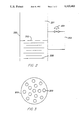
- FIG. 2 is a plan view of the liquid flow restriction in a single column.
- FIG. 3 is top view of a perforated plate useful in the column of FIG. 2.
- FIG. 1 shows a simple flow diagram of a process using the present invention.
- the particular process shown is for the production of methyl tertiary butyl ether (MTBE) from the reaction of methanol and isobutene in a mixed butene/butane feed stream.
- MTBE methyl tertiary butyl ether
- U.S. Pat. No. 4,307,254 which is herein incorporated by reference.
- a first distillation column 1 which contains an acid cation exchange resin packing 7 suitable for the reaction.
- the acid cation exchange resin catalyst 7 is suitably disposed in the column 1 as described in U.S. Pat. No. 4,307,254 to act as both a catalyst and distillation structure.
- the methanol and mixed butene/butane stream is fed to the first column 1 into the catalyst 7 in a feed zone via flow lines 5 and 6.
- the methanol reacts with the isobutene in the catalyst bed or reaction distillation zone to form MTBE.
- the unreacted components of the mixed butene/butane stream are distilled off overhead and recovered via flow line 8.
- the MTBE product is distilled off toward the bottom since the temperature of the catalyst (reaction distillation) zone is maintained at the boiling of the reactants at the operating pressure of the column, which is lower than the boiling point of the MTBE.
- the bottoms liquid product containing MTBE and some dissolved unreacted methanol and C 4 hydrocarbons is carried out the bottom of the first column 1 via flow line 3 to the top of second column 2 where the MTBE is more completely separated from any dissolved methanol or C 4 's in a conventional distillation column 2 having trays as shown or inert packing and recovered via flow line 9.
- the unreacted materials are recovered overhead via flow line 4 which carries them back as vapors to the bottom of the first column 1.
- a level controller 10 is secured to the first column 1 and senses a liquid level in the first column 1 (as by a differential pressure) and operates flow control valve 11 which acts as a liquid flow restriction between the two columns and maintains a desired preset liquid level in the catalyst bed 7 of column I. Note the level control 10 may be positioned to detect the level over any portion of the column 1.
- Example I shows a comparison of one such unit operated with and without the liquid level in the catalyst bed.
- FIG. 2 illustrates an arrangement which may be used if only one column is used. Only that portion of the column is illustrated that is used to maintain the liquid level in the catalyst bed.
- the column 200 has a bed of catalyst 201 which acts as a distillation structure.
- a perforated plate 202 which supports the catalyst bed 201.
- the plate 202 as indicated in FIG. 3 is perforated to allow gas passage upward into the catalyst bed 201 yet provides a sufficient pressure drop to allow a liquid level to build up above the plate in the bed 201.
- the plate is approximately 5-20 percent open space.
- a liquid bypass flow line 203 is provided about the plate 202 to give added control of the level.
- Valve 204 in bypass 203 may be opened or closed in response to a differential pressure (indicating liquid level) to control the liquid level. If desired the valve can be part of a control loop (not shown) responding to a liquid level controller.
- a standard distillation tray may be substituted for the perforated plate 202.
- the downcomer area of the standard tray is blocked and the by pass flow line 203 used to control the liquid level in the bed.
- a commercial catalytic distillation process for the production of MTBE was operated according to that disclosed in U.S. Pat. No. 4,307,254. Following an incident in which the catalyst was partially deactivated, the operation was changed to maintain the liquid level at the top of the catalyst zone. The arrangement was similar to that shown in FIG. 1. A control valve acted as a restriction in the liquid flow line 3 to control the liquid level which was sensed by a differential pressure in the distillation reaction column 1. Unexpectedly, the performance of the commercial unit with the damaged catalyst was almost equal to the unit with undamaged catalyst.
- the method and structure have been found to be particularly useful for conducting the catalytic distillation production of tertiary butyl alcohol (TBA) from the hydration of isobutylene.
- TBA tertiary butyl alcohol
- a stream containing isobutylene is fed to the column below the catalyst bed and water is fed above the catalyst bed.
- the catalyst bed contains an acid cation exchange resin as described in U.S. Pat. No. 4,307,254 and is placed into the one inch laboratory column in the manner described therein. Unreacted butylene, water and inerts (such as other C 4 's) are taken overhead and the TBA product is recovered as bottoms.
- Water must be present in amounts sufficient to maintain the catalyst in a hydrated state plus enough for the reaction and to accommodate the water azeotropes in the system.
- One method of control is to measure the amount of water present in the TBA fraction within the column and to maintain that amount above zero but below the azeotropic concentration at the temperature and pressure used.
- the catalyst performs satisfactorily at first but quickly loses its selectivity due to loss of water despite the control technique outlined above. This may be attributed to mass transfer and distribution problems within the catalyst bed. It has been found that maintaining a liquid level in the catalyst bed using the technique of FIG.S 2 and 3 maintains the wetted state of the catalyst and allows high selectivity toward tertiary butyl alcohol production. Table I below compares the results of the process with and without the liquid level in the bed. The liquid level in the catalyst bed is indicated by the high differential pressure across the bed. In the test runs, a 1" diameter tower was used ten feet in length. Four feet of Rohm and Haas Amberlyst 15 catalyst was inserted into the column in a pocketed belt twisted with wire mesh.
- the pilot plant was run as described in commonly assigned U.S. pat. appln. Ser. No. 122,485 filed Nov. 16, 1987 using a 3" pilot plant column with Union Carbide LZY-82 molecular sieve in the pockets of the catalyst structure for the production of cumene from the alkylation of benzene with propylene.
- the use of the liquid level as measured by the differential pressure across the bed improved performance of the catalyst and process.
- Table II below shows comparative data between the normal operation and with the liquid level.
- liquid level may be maintained at any location within the catalyst bed using the techniques disclosed in either FIG.S 2 and 3.
Landscapes
- Chemical & Material Sciences (AREA)
- Organic Chemistry (AREA)
- Chemical Kinetics & Catalysis (AREA)
- Crystallography & Structural Chemistry (AREA)
- Organic Low-Molecular-Weight Compounds And Preparation Thereof (AREA)
- Vaporization, Distillation, Condensation, Sublimation, And Cold Traps (AREA)
Abstract
A method and apparatus for conducting a catalytic distillation process is provided which allows for maintaining a liquid level in selected portions of the catalyst bed. Three particular processes disclosed are the production of methyl tertiary butyl ether, tertiary butyl alcohol and cumene.
Description
This is a division of application Ser. No. 07/328,478, filed Mar. 23, 1989.
1. Field of the invention
The present invention relates to an improvement in the manner of conducting concurrent reactions and distillations wherein the catalyst is also the distillation structure.
2. Related art
Recently a new method of carrying out catalytic reactions has been developed, wherein the components of the reaction system are concurrently separable by distillation, using the catalyst structures as the distillation structures. This method is now generally known as catalytic distillation and any reference to catalytic distillation herein will be taken to mean this method or process. Such systems are described variously in U.S. Pat. Nos. 4,215,011; 4,232,177; 4,242,530; 4,302,356; 4,307,254; 4,336,407; 4,439,350; 4,443,559; and 4,482,775 commonly assigned herewith.
Briefly, a preferred and commercial catalyst structure described in the above patents comprises a cloth belt with a plurality of pockets spaced along the belt and containing particulate catalyst material, said cloth belt being wound in a helix about a spacing material such as stainless steel knitted mesh. These units are then disposed in the distillation column reactor. In addition, commonly assigned U.S. Pat. Nos. 4,443,559 and 4,250,052 disclose a variety of catalyst structures for this use and are incorporated herein.
The success of catalytic distillation lies in an understanding of the principles associated with distillation. First, because the reaction is occurring concurrently with distillation, the initial reaction product is removed from the reaction zone as quickly as it is formed. The removal of the reaction product minimizes further reaction, decomposition, polymerization and the like. Second, because in a distillation the compounds are boiling, the temperature of the reaction is controlled by the boiling point of the mixture at the system pressure. The heat of the reaction simply creates more boil up, but no increase in temperature. Third, the reaction has an increased driving force because the reaction products have been removed and cannot contribute to a reverse reaction (Le Chatelier's Principle).
The distillation parts of the above disclosures have been conventional, i.e., counter-current vapor liquid flow in the packed catalyst bed with the catalyst acting as the contact structure, at least in the reaction zone. The reaction zone having the catalyst packing is designated the reaction distillation zone to distinguish it from other distillation zones which contain either inert packing or conventional distillation trays. The conventional distillation zones may be above or below the distillation reaction zone according to the separation desired.
In one particular embodiment for making methyl tertiary butyl ether, the physical embodiment of the distillation column reactor includes a separate distillation zone below the distillation reaction zone to insure that the unreacted feed components are removed from the ether product which is taken off as bottoms product. In at least one case the lower distillation zone is a separate distillation column connected to another distillation column which contains the catalyst. Vapor and liquid flow lines are provided so that essentially the two columns act as one.
Because of the nature of the distillation the reactants and products are separated. Depending upon the components, however, the reactants may be separated before the desired reaction is completed requiring recycle. It was thus seen to be desirable to retain the reactants in contact with the catalyst while still separating out the products.
Briefly the present invention is the discovery that the reaction rate can be increased by improving the contact of the liquid with the catalyst, which is accomplished by increasing the liquid level in the reaction distillation zone This is achieved by a liquid flow restrictor between the distillation reaction zone and the lower distillation zone. That is, the vapor from below may rise up to (and through) the reaction distillation zone as in a conventional or prior operation but a portion of the liquid is maintained there. If a single distillation column reactor is used, a conventional distillation tray with the downcomer area blocked is located between the reaction distillation zone and the distillation zone. A by pass line for liquid flow is provided about the tray and a valve is provided in the liquid flow conduit to restrict liquid downflow and thereby to build up a liquid level above that tray just below the catalyst bed. Alternatively a perforated plate may be used to support the catalyst and cause a liquid pressure drop in the column thus building up a level in the catalyst. If the two column system is used, then a valve or other restriction means is placed in the liquid flow line between the two columns.
While the particular position of the liquid level has been described above to be at the lower end of the distillation reaction zone, it could just as easily be placed anywhere in the catalyst bed depending upon the desired reactions.
The term "liquid level" is used herein to mean an increased density of the material in the reaction distillation zone over that of a pure distillation as distinguished from a continuous liquid phase. The phase system as present in the reaction distillation zone is physically a froth. This is the result of the vapor traveling up through the liquid retained in the zone.
Another way of viewing this is that in normal distillation there is a vapor with liquid (internal reflux) trickling down through the vapor and contacting the catalyst whereas in the present "flooded" system the vapor is traveling up through a liquid phase to create the froth or foam.
Hence in essence the benefits of the distillation are still obtained, i.e., separating the various components by the distillation whereas the increased liquid volume in contact with the catalyst improves the synthesis reaction.
FIG. 1 is a flow diagram of one embodiment of the invention showing separate columns for the distillation and reaction zones.
FIG. 2 is a plan view of the liquid flow restriction in a single column.
FIG. 3 is top view of a perforated plate useful in the column of FIG. 2.
Referring now to the Fig.s a detailed description of the preferred embodiments can be appreciated.
FIG. 1 shows a simple flow diagram of a process using the present invention. The particular process shown is for the production of methyl tertiary butyl ether (MTBE) from the reaction of methanol and isobutene in a mixed butene/butane feed stream. For a detailed description of the process the reader is referred to U.S. Pat. No. 4,307,254 which is herein incorporated by reference. Generally there is shown a first distillation column 1 which contains an acid cation exchange resin packing 7 suitable for the reaction. The acid cation exchange resin catalyst 7 is suitably disposed in the column 1 as described in U.S. Pat. No. 4,307,254 to act as both a catalyst and distillation structure. The methanol and mixed butene/butane stream is fed to the first column 1 into the catalyst 7 in a feed zone via flow lines 5 and 6. The methanol reacts with the isobutene in the catalyst bed or reaction distillation zone to form MTBE. The unreacted components of the mixed butene/butane stream are distilled off overhead and recovered via flow line 8. At the same time the MTBE product is distilled off toward the bottom since the temperature of the catalyst (reaction distillation) zone is maintained at the boiling of the reactants at the operating pressure of the column, which is lower than the boiling point of the MTBE.
The bottoms liquid product containing MTBE and some dissolved unreacted methanol and C4 hydrocarbons is carried out the bottom of the first column 1 via flow line 3 to the top of second column 2 where the MTBE is more completely separated from any dissolved methanol or C4 's in a conventional distillation column 2 having trays as shown or inert packing and recovered via flow line 9. The unreacted materials are recovered overhead via flow line 4 which carries them back as vapors to the bottom of the first column 1. A level controller 10 is secured to the first column 1 and senses a liquid level in the first column 1 (as by a differential pressure) and operates flow control valve 11 which acts as a liquid flow restriction between the two columns and maintains a desired preset liquid level in the catalyst bed 7 of column I. Note the level control 10 may be positioned to detect the level over any portion of the column 1.
Pumps, compressors, and other operating equipment are not shown as they are conventional and readily selected by those of ordinary skill in the art of distillation column design. Example I shows a comparison of one such unit operated with and without the liquid level in the catalyst bed.
FIG. 2 illustrates an arrangement which may be used if only one column is used. Only that portion of the column is illustrated that is used to maintain the liquid level in the catalyst bed.
In FIG. 2 the column 200 has a bed of catalyst 201 which acts as a distillation structure. Directly below the catalyst bed 201 is shown a perforated plate 202 which supports the catalyst bed 201. The plate 202 as indicated in FIG. 3 is perforated to allow gas passage upward into the catalyst bed 201 yet provides a sufficient pressure drop to allow a liquid level to build up above the plate in the bed 201. The plate is approximately 5-20 percent open space. A liquid bypass flow line 203 is provided about the plate 202 to give added control of the level. Valve 204 in bypass 203 may be opened or closed in response to a differential pressure (indicating liquid level) to control the liquid level. If desired the valve can be part of a control loop (not shown) responding to a liquid level controller.
Alternatively a standard distillation tray may be substituted for the perforated plate 202. The downcomer area of the standard tray is blocked and the by pass flow line 203 used to control the liquid level in the bed.
A commercial catalytic distillation process for the production of MTBE was operated according to that disclosed in U.S. Pat. No. 4,307,254. Following an incident in which the catalyst was partially deactivated, the operation was changed to maintain the liquid level at the top of the catalyst zone. The arrangement was similar to that shown in FIG. 1. A control valve acted as a restriction in the liquid flow line 3 to control the liquid level which was sensed by a differential pressure in the distillation reaction column 1. Unexpectedly, the performance of the commercial unit with the damaged catalyst was almost equal to the unit with undamaged catalyst.
The method and structure have been found to be particularly useful for conducting the catalytic distillation production of tertiary butyl alcohol (TBA) from the hydration of isobutylene. In the TBA process a stream containing isobutylene is fed to the column below the catalyst bed and water is fed above the catalyst bed. The catalyst bed contains an acid cation exchange resin as described in U.S. Pat. No. 4,307,254 and is placed into the one inch laboratory column in the manner described therein. Unreacted butylene, water and inerts (such as other C4 's) are taken overhead and the TBA product is recovered as bottoms.
Water must be present in amounts sufficient to maintain the catalyst in a hydrated state plus enough for the reaction and to accommodate the water azeotropes in the system. One method of control is to measure the amount of water present in the TBA fraction within the column and to maintain that amount above zero but below the azeotropic concentration at the temperature and pressure used.
Without the liquid level, the catalyst performs satisfactorily at first but quickly loses its selectivity due to loss of water despite the control technique outlined above. This may be attributed to mass transfer and distribution problems within the catalyst bed. It has been found that maintaining a liquid level in the catalyst bed using the technique of FIG.S 2 and 3 maintains the wetted state of the catalyst and allows high selectivity toward tertiary butyl alcohol production. Table I below compares the results of the process with and without the liquid level in the bed. The liquid level in the catalyst bed is indicated by the high differential pressure across the bed. In the test runs, a 1" diameter tower was used ten feet in length. Four feet of Rohm and Haas Amberlyst 15 catalyst was inserted into the column in a pocketed belt twisted with wire mesh.
In one other example the pilot plant was run as described in commonly assigned U.S. pat. appln. Ser. No. 122,485 filed Nov. 16, 1987 using a 3" pilot plant column with Union Carbide LZY-82 molecular sieve in the pockets of the catalyst structure for the production of cumene from the alkylation of benzene with propylene. Again, the use of the liquid level as measured by the differential pressure across the bed improved performance of the catalyst and process. Table II below shows comparative data between the normal operation and with the liquid level.
While particular configurations have been shown, it should be understood that the liquid level may be maintained at any location within the catalyst bed using the techniques disclosed in either FIG.S 2 and 3.
Claims (9)
1. A method for operating a catalytic distillation process, comprising the steps of:
(a) introducing reactants into a feed zone of a distillation reaction column having an upper zone containing a catalytic distillation structure which defines a reaction distillation zone and a lower zone containing conventional inert distillation structure which defines a distillation zone;
(b) simultaneously in said reaction distillation zone
(1) reacting at least a portion of the reactants to form reaction products, and
(2) separating the reaction products and/or reactants by fractional distillation;
(c) restricting the downward flow of internal reflux between said reaction distillation zone and said distillation zone to maintain a liquid level above the restriction for additional contact and reaction of the liquid and distillation vapors, said liquid level being a froth characterized as having an increased density of the material in the reaction distillation zone compared to a distillation carried out in the absence of said froth.
2. The method of claim 1 wherein said lower distillation zone is contiguous to said upper reaction distillation zone.
3. The method of claim 1 wherein said lower distillation zone is separated from said upper reaction distillation zone and is in fluid communication therewith for vapor and liquid flows therebetween.
4. The method of claim 2 wherein said downward flow is restricted by a perforated plate and said liquid level is controlled by means of a by-pass line around said perforated plate, said by-pass line including a control valve responsive to said liquid level.
5. The method of claim 3 wherein said downward flow is restricted by a control valve in the liquid communication between said upper reaction distillation zone and said lower distillation zone, said control valve operating in response to said liquid level.
6. A method for operating a catalytic distillation process, comprising the steps of:
(a) introducing reactants into a feed zone of a distillation reaction column having an upper reaction distillation zone containing a catalytic distillation structure and a lower distillation zone containing conventional inert distillation structure;
(b) simultaneously in said upper reaction distillation zone
(1) reacting at least a portion of the reactants to form reaction products, and
(2) separating the reaction products and/or reactants by fractional distillation;
(c) restricting the downward flow of internal reflux between said upper and lower zones to maintain a froth level in said upper zone having an increased density of the material in the reaction distillation zone compared to a distillation carried out in the absence of said froth; and
(d) fractionating by fractional distillation reactants and/or reaction products in said lower distillation zone.
7. The method of claim 6 wherein the level of said froth is detected and controlled by the differential pressure across said reaction distillation zone compared to the differential pressure across said reaction distillation zone absent said froth.
8. A method for operating a catalytic distillation process, comprising the steps of:
(a) introducing reactants into a feed zone of a distillation reaction column having an upper reaction distillation zone containing a catalytic distillation structure and a lower distillation zone containing conventional inert distillation structure;
(b) simultaneously in said upper reaction distillation zone
(1) reacting at least a portion of the reactants to form reaction products, and
(2) separating the reaction products and/or reactants by fractional distillation;
(c) measuring the differential pressure across said upper reaction distillation zone;
(d) controlling the downward flow of internal reflux between said upper and lower zones in response to said differential pressure measurement to maintain a froth level in said upper zone having an increased density of the material in the reaction distillation zone compared to a distillation carried out in the absence of said froth; and
(e) fractionating by fractional distillation reactants and/or reaction products in said lower distillation zone.
9. A method for operating a catalytic distillation process, comprising the steps of:
(a) introducing reactants into a feed zone of a distillation reaction column having an upper zone containing a catalytic distillation structure which defines a reaction distillation zone and a lower zone containing conventional inert distillation structure which defines a distillation zone;
(b) simultaneously in said reaction distillation zone
(1) reacting at least a portion of the reactants to form reaction products, and
(2) separating the reaction products and/or reactants by fractional distillation; and
(c) restricting the downward flow of internal reflux between said reaction distillation zone and said distillation zone to maintain a liquid level above the restriction for additional contact and reaction of the liquid and distillation vapors, said liquid level being a froth characterized as having an increased density of the material in the reaction distillation zone compared to a distillation carried out in the absence of said froth; and
(d) detecting and controlling said liquid level by the differential pressure across said reaction distillation zone compared to the differential pressure across said reaction distillation zone absent said froth.
Priority Applications (2)
| Application Number | Priority Date | Filing Date | Title |
|---|---|---|---|
| US07/689,981 US5120403A (en) | 1989-03-23 | 1991-04-08 | Method for operating a catalytic distillation process |
| US07/840,267 US5345006A (en) | 1989-03-23 | 1992-02-24 | Method and apparatus for operating a catalytic distillation process |
Applications Claiming Priority (2)
| Application Number | Priority Date | Filing Date | Title |
|---|---|---|---|
| US32848789A | 1989-03-23 | 1989-03-23 | |
| US07/689,981 US5120403A (en) | 1989-03-23 | 1991-04-08 | Method for operating a catalytic distillation process |
Related Parent Applications (1)
| Application Number | Title | Priority Date | Filing Date |
|---|---|---|---|
| US32848789A Division | 1989-03-23 | 1989-03-23 |
Related Child Applications (1)
| Application Number | Title | Priority Date | Filing Date |
|---|---|---|---|
| US07/840,267 Division US5345006A (en) | 1989-03-23 | 1992-02-24 | Method and apparatus for operating a catalytic distillation process |
Publications (1)
| Publication Number | Publication Date |
|---|---|
| US5120403A true US5120403A (en) | 1992-06-09 |
Family
ID=26986400
Family Applications (2)
| Application Number | Title | Priority Date | Filing Date |
|---|---|---|---|
| US07/689,981 Expired - Lifetime US5120403A (en) | 1989-03-23 | 1991-04-08 | Method for operating a catalytic distillation process |
| US07/840,267 Expired - Fee Related US5345006A (en) | 1989-03-23 | 1992-02-24 | Method and apparatus for operating a catalytic distillation process |
Family Applications After (1)
| Application Number | Title | Priority Date | Filing Date |
|---|---|---|---|
| US07/840,267 Expired - Fee Related US5345006A (en) | 1989-03-23 | 1992-02-24 | Method and apparatus for operating a catalytic distillation process |
Country Status (1)
| Country | Link |
|---|---|
| US (2) | US5120403A (en) |
Cited By (15)
| Publication number | Priority date | Publication date | Assignee | Title |
|---|---|---|---|---|
| US5221441A (en) * | 1989-03-23 | 1993-06-22 | Chemical Research & Licensing Company | Method for operating a catalytic distillation process |
| US5334536A (en) * | 1991-06-12 | 1994-08-02 | Klaus Nonnenmacher | Apparatus for the photometric determination of gas concentrations |
| US5414147A (en) * | 1993-08-24 | 1995-05-09 | Global Octanes Corporation | Method for improving conversion of isobutylene in MTBE process |
| US5447609A (en) * | 1990-02-06 | 1995-09-05 | Koch Engineering Company, Inc. | Catalytic reaction and mass transfer process |
| US5593548A (en) * | 1990-02-06 | 1997-01-14 | Koch Engineering Company, Inc. | Method for concurrent reaction with distillation |
| US5604298A (en) * | 1995-12-07 | 1997-02-18 | In Usa, Inc. | Gas measurement system |
| US5628880A (en) * | 1996-02-12 | 1997-05-13 | Chemical Research & Licensing Company | Etherification--hydrogenation process |
| US5770782A (en) * | 1996-02-08 | 1998-06-23 | Huntsman Petrochemical Corporation | Process and system for alkylation of aromatic compounds |
| US5777187A (en) * | 1996-02-08 | 1998-07-07 | Huntsman Petrochemical Corporation | Two-step process for alkylation of benzene to form linear alkylbenzenes |
| US6133492A (en) * | 1996-02-08 | 2000-10-17 | Huntsman Petrochemical Corporation | Alkylation of benzene to form linear alkylbenzenes using fluorine-containing mordenites |
| US6166281A (en) * | 1996-02-08 | 2000-12-26 | Huntsman Petrochemical Corporation | Alkylation of benzene to form linear alkylbenzenes using fluorine-containing mordenites |
| US6657090B2 (en) | 2000-10-19 | 2003-12-02 | Oxeno Olefinchemie Gmbh | Process for preparing highly pure raffinate II and Methyl tert-butyl ether |
| US20060178544A1 (en) * | 2005-02-08 | 2006-08-10 | Murray Brendan D | Selective alkylation of aromatic hydrocarbons |
| US20060281958A1 (en) * | 2005-06-14 | 2006-12-14 | Genoveva Buelna | Catalytic reactive separation system for energy-efficient production of cumene |
| US20080251127A1 (en) * | 2007-04-10 | 2008-10-16 | Laurent Zuber | Reflux divider for a column having portions for the transfer of material arranged in parallel |
Families Citing this family (4)
| Publication number | Priority date | Publication date | Assignee | Title |
|---|---|---|---|---|
| US6906229B1 (en) | 2000-02-29 | 2005-06-14 | Exxonmobil Chemical Patents, Inc. | Process for hydrolyzing di-isopropyl ether to isopropyl alcohol by catalytic distillation using a solid acid catalyst |
| US6548718B2 (en) | 2000-04-27 | 2003-04-15 | Shell Oil Company | Process for catalytic hydroxylation of, saturated or unsaturated, aliphatic compounds |
| US6437197B1 (en) | 2000-04-27 | 2002-08-20 | Shell Oil Company | Process for catalytic hydroxylation of aromatic hydrocarbons |
| US6596913B1 (en) | 2001-02-23 | 2003-07-22 | Catalytic Distillation Technologies | Recovery of tertiary butyl alcohol |
Citations (20)
| Publication number | Priority date | Publication date | Assignee | Title |
|---|---|---|---|---|
| US2816858A (en) * | 1953-09-25 | 1957-12-17 | Phillips Petroleum Co | Method of controlling fractionating column reflux |
| US3011956A (en) * | 1960-03-15 | 1961-12-05 | Detrex Chem Ind | Automatic drycleaning still |
| US3027307A (en) * | 1959-08-17 | 1962-03-27 | Standard Oil Co | Reduction of distillation tower foaming |
| US3401092A (en) * | 1966-04-22 | 1968-09-10 | Phillips Petroleum Co | Two-zone distillation process and system having vapor flows controlled by the pressure differential |
| US4089752A (en) * | 1974-04-24 | 1978-05-16 | Sun Ventures, Inc. | Distillation column reactor and process |
| US4215011A (en) * | 1979-02-21 | 1980-07-29 | Chemical Research And Licensing Company | Catalyst system for separating isobutene from C4 streams |
| US4232177A (en) * | 1979-02-21 | 1980-11-04 | Chemical Research & Licensing Company | Catalytic distillation process |
| US4242530A (en) * | 1978-07-27 | 1980-12-30 | Chemical Research & Licensing Company | Process for separating isobutene from C4 streams |
| US4250052A (en) * | 1978-09-08 | 1981-02-10 | Chemical Research & Licensing Company | Catalyst structure and a process for its preparation |
| US4302356A (en) * | 1978-07-27 | 1981-11-24 | Chemical Research & Licensing Co. | Process for separating isobutene from C4 streams |
| US4307254A (en) * | 1979-02-21 | 1981-12-22 | Chemical Research & Licensing Company | Catalytic distillation process |
| US4336407A (en) * | 1980-02-25 | 1982-06-22 | Chemical Research & Licensing Company | Catalytic distillation process |
| US4439350A (en) * | 1982-06-21 | 1984-03-27 | Chemical Research & Licensing Company | Contact structure for use in catalytic distillation |
| US4443559A (en) * | 1981-09-30 | 1984-04-17 | Chemical Research & Licensing Company | Catalytic distillation structure |
| US4475005A (en) * | 1981-04-10 | 1984-10-02 | Snamprogetti S.P.A. | Process for preparing tertiary alkyl ethers |
| US4482775A (en) * | 1982-09-22 | 1984-11-13 | Chemical Research & Licensing Company | Isomerization of C4 alkenes |
| US4550012A (en) * | 1984-05-01 | 1985-10-29 | Mobil Oil Corp. | Multi-phase countercurrent reactor system |
| US4847431A (en) * | 1988-03-08 | 1989-07-11 | Institut Francais Du Petrole | Process for manufacturing a tertiary alkyl ether by reactive distillation |
| US4847430A (en) * | 1988-03-21 | 1989-07-11 | Institut Francais Du Petrole | Process for manufacturing a tertiary alkyl ether by reactive distillation |
| US4978807A (en) * | 1989-03-23 | 1990-12-18 | Chemical Research & Licensing Company | Method for the preparation of methyl tertiary butyl ether |
Family Cites Families (1)
| Publication number | Priority date | Publication date | Assignee | Title |
|---|---|---|---|---|
| US4982022A (en) * | 1989-08-28 | 1991-01-01 | Chemical Research & Licensing Company | Process for the preparation of tertiary alcohols |
-
1991
- 1991-04-08 US US07/689,981 patent/US5120403A/en not_active Expired - Lifetime
-
1992
- 1992-02-24 US US07/840,267 patent/US5345006A/en not_active Expired - Fee Related
Patent Citations (20)
| Publication number | Priority date | Publication date | Assignee | Title |
|---|---|---|---|---|
| US2816858A (en) * | 1953-09-25 | 1957-12-17 | Phillips Petroleum Co | Method of controlling fractionating column reflux |
| US3027307A (en) * | 1959-08-17 | 1962-03-27 | Standard Oil Co | Reduction of distillation tower foaming |
| US3011956A (en) * | 1960-03-15 | 1961-12-05 | Detrex Chem Ind | Automatic drycleaning still |
| US3401092A (en) * | 1966-04-22 | 1968-09-10 | Phillips Petroleum Co | Two-zone distillation process and system having vapor flows controlled by the pressure differential |
| US4089752A (en) * | 1974-04-24 | 1978-05-16 | Sun Ventures, Inc. | Distillation column reactor and process |
| US4302356A (en) * | 1978-07-27 | 1981-11-24 | Chemical Research & Licensing Co. | Process for separating isobutene from C4 streams |
| US4242530A (en) * | 1978-07-27 | 1980-12-30 | Chemical Research & Licensing Company | Process for separating isobutene from C4 streams |
| US4250052A (en) * | 1978-09-08 | 1981-02-10 | Chemical Research & Licensing Company | Catalyst structure and a process for its preparation |
| US4307254A (en) * | 1979-02-21 | 1981-12-22 | Chemical Research & Licensing Company | Catalytic distillation process |
| US4232177A (en) * | 1979-02-21 | 1980-11-04 | Chemical Research & Licensing Company | Catalytic distillation process |
| US4215011A (en) * | 1979-02-21 | 1980-07-29 | Chemical Research And Licensing Company | Catalyst system for separating isobutene from C4 streams |
| US4336407A (en) * | 1980-02-25 | 1982-06-22 | Chemical Research & Licensing Company | Catalytic distillation process |
| US4475005A (en) * | 1981-04-10 | 1984-10-02 | Snamprogetti S.P.A. | Process for preparing tertiary alkyl ethers |
| US4443559A (en) * | 1981-09-30 | 1984-04-17 | Chemical Research & Licensing Company | Catalytic distillation structure |
| US4439350A (en) * | 1982-06-21 | 1984-03-27 | Chemical Research & Licensing Company | Contact structure for use in catalytic distillation |
| US4482775A (en) * | 1982-09-22 | 1984-11-13 | Chemical Research & Licensing Company | Isomerization of C4 alkenes |
| US4550012A (en) * | 1984-05-01 | 1985-10-29 | Mobil Oil Corp. | Multi-phase countercurrent reactor system |
| US4847431A (en) * | 1988-03-08 | 1989-07-11 | Institut Francais Du Petrole | Process for manufacturing a tertiary alkyl ether by reactive distillation |
| US4847430A (en) * | 1988-03-21 | 1989-07-11 | Institut Francais Du Petrole | Process for manufacturing a tertiary alkyl ether by reactive distillation |
| US4978807A (en) * | 1989-03-23 | 1990-12-18 | Chemical Research & Licensing Company | Method for the preparation of methyl tertiary butyl ether |
Cited By (18)
| Publication number | Priority date | Publication date | Assignee | Title |
|---|---|---|---|---|
| US5221441A (en) * | 1989-03-23 | 1993-06-22 | Chemical Research & Licensing Company | Method for operating a catalytic distillation process |
| US5447609A (en) * | 1990-02-06 | 1995-09-05 | Koch Engineering Company, Inc. | Catalytic reaction and mass transfer process |
| US5593548A (en) * | 1990-02-06 | 1997-01-14 | Koch Engineering Company, Inc. | Method for concurrent reaction with distillation |
| US5334536A (en) * | 1991-06-12 | 1994-08-02 | Klaus Nonnenmacher | Apparatus for the photometric determination of gas concentrations |
| US5414147A (en) * | 1993-08-24 | 1995-05-09 | Global Octanes Corporation | Method for improving conversion of isobutylene in MTBE process |
| US5604298A (en) * | 1995-12-07 | 1997-02-18 | In Usa, Inc. | Gas measurement system |
| US5777187A (en) * | 1996-02-08 | 1998-07-07 | Huntsman Petrochemical Corporation | Two-step process for alkylation of benzene to form linear alkylbenzenes |
| US5770782A (en) * | 1996-02-08 | 1998-06-23 | Huntsman Petrochemical Corporation | Process and system for alkylation of aromatic compounds |
| US6133492A (en) * | 1996-02-08 | 2000-10-17 | Huntsman Petrochemical Corporation | Alkylation of benzene to form linear alkylbenzenes using fluorine-containing mordenites |
| US6166281A (en) * | 1996-02-08 | 2000-12-26 | Huntsman Petrochemical Corporation | Alkylation of benzene to form linear alkylbenzenes using fluorine-containing mordenites |
| US5628880A (en) * | 1996-02-12 | 1997-05-13 | Chemical Research & Licensing Company | Etherification--hydrogenation process |
| US6657090B2 (en) | 2000-10-19 | 2003-12-02 | Oxeno Olefinchemie Gmbh | Process for preparing highly pure raffinate II and Methyl tert-butyl ether |
| US20060178544A1 (en) * | 2005-02-08 | 2006-08-10 | Murray Brendan D | Selective alkylation of aromatic hydrocarbons |
| US7348465B2 (en) | 2005-02-08 | 2008-03-25 | Shell Oil Company | Selective alkylation of aromatic hydrocarbons |
| US20060281958A1 (en) * | 2005-06-14 | 2006-12-14 | Genoveva Buelna | Catalytic reactive separation system for energy-efficient production of cumene |
| US7566429B2 (en) | 2005-06-14 | 2009-07-28 | Sandia Corporation | Catalytic reactive separation system for energy-efficient production of cumene |
| US20080251127A1 (en) * | 2007-04-10 | 2008-10-16 | Laurent Zuber | Reflux divider for a column having portions for the transfer of material arranged in parallel |
| US8052845B2 (en) * | 2007-04-10 | 2011-11-08 | Sulzer Chemtech Ag | Reflux divider for a column having portions for the transfer of material arranged in parallel |
Also Published As
| Publication number | Publication date |
|---|---|
| US5345006A (en) | 1994-09-06 |
Similar Documents
| Publication | Publication Date | Title |
|---|---|---|
| US4978807A (en) | Method for the preparation of methyl tertiary butyl ether | |
| US5120403A (en) | Method for operating a catalytic distillation process | |
| US4982022A (en) | Process for the preparation of tertiary alcohols | |
| US5248836A (en) | Process for the preparation of ETBE | |
| US4307254A (en) | Catalytic distillation process | |
| US4232177A (en) | Catalytic distillation process | |
| EP0487264B1 (en) | Process for the preparation of MTBE | |
| EP0008860B1 (en) | Catalyst system | |
| US4504687A (en) | Method for etherifications | |
| US4475005A (en) | Process for preparing tertiary alkyl ethers | |
| US4336407A (en) | Catalytic distillation process | |
| US4471154A (en) | Staged, fluidized-bed distillation-reactor and a process for using such reactor | |
| KR100242919B1 (en) | Reactive distillation method and apparatus for carrying out this | |
| US4847430A (en) | Process for manufacturing a tertiary alkyl ether by reactive distillation | |
| US7030277B2 (en) | Process and apparatus for catalytic distillations | |
| US5026459A (en) | Apparatus for reactive distillation | |
| US5262576A (en) | Method for the alkylation of organic aromatic compounds | |
| US5221441A (en) | Method for operating a catalytic distillation process | |
| RU2055829C1 (en) | Process for preparing methyl-tret-butyl ether, ethyl- tret-butyl ether of ethyl tret-amyl-ether, and device for carrying out reactive distillation | |
| US5204064A (en) | Apparatus for conducting a catalytic distillation process | |
| EP0466954A1 (en) | Catalytic distillation | |
| US5523061A (en) | Equipment for catalytic distillation | |
| US5248837A (en) | Method for controlling catalytic distillation etherifications | |
| US5231234A (en) | Two stage production of ether from tertiary alcohol | |
| EP0485078B1 (en) | Process for the production of MTBE |
Legal Events
| Date | Code | Title | Description |
|---|---|---|---|
| STCF | Information on status: patent grant |
Free format text: PATENTED CASE |
|
| FEPP | Fee payment procedure |
Free format text: PAYOR NUMBER ASSIGNED (ORIGINAL EVENT CODE: ASPN); ENTITY STATUS OF PATENT OWNER: LARGE ENTITY |
|
| FPAY | Fee payment |
Year of fee payment: 4 |
|
| AS | Assignment |
Owner name: CATALYTIC DISTILLATION TECHNOLOGIES, TEXAS Free format text: ASSIGNMENT OF ASSIGNORS INTEREST;ASSIGNOR:CHEMICAL RESEARCH & LICENSING COMPANY;REEL/FRAME:008907/0807 Effective date: 19980115 |
|
| FPAY | Fee payment |
Year of fee payment: 8 |
|
| FPAY | Fee payment |
Year of fee payment: 12 |