US511751A - Carbon-machine - Google Patents
Carbon-machine Download PDFInfo
- Publication number
- US511751A US511751A US511751DA US511751A US 511751 A US511751 A US 511751A US 511751D A US511751D A US 511751DA US 511751 A US511751 A US 511751A
- Authority
- US
- United States
- Prior art keywords
- mold
- molds
- press
- furnace
- drums
- Prior art date
- Legal status (The legal status is an assumption and is not a legal conclusion. Google has not performed a legal analysis and makes no representation as to the accuracy of the status listed.)
- Expired - Lifetime
Links
- 229910052799 carbon Inorganic materials 0.000 description 8
- OKTJSMMVPCPJKN-UHFFFAOYSA-N carbon Chemical compound [C] OKTJSMMVPCPJKN-UHFFFAOYSA-N 0.000 description 6
- 239000003575 carbonaceous material Substances 0.000 description 6
- 239000000203 mixture Substances 0.000 description 6
- 238000004140 cleaning Methods 0.000 description 4
- 238000000034 method Methods 0.000 description 4
- 238000005452 bending Methods 0.000 description 2
- 238000010276 construction Methods 0.000 description 2
- 230000000875 corresponding Effects 0.000 description 2
- 238000010438 heat treatment Methods 0.000 description 2
- 239000000463 material Substances 0.000 description 2
- 230000002093 peripheral Effects 0.000 description 2
- 230000036633 rest Effects 0.000 description 2
- 230000000284 resting Effects 0.000 description 2
Images

Classifications
-
- B—PERFORMING OPERATIONS; TRANSPORTING
- B29—WORKING OF PLASTICS; WORKING OF SUBSTANCES IN A PLASTIC STATE IN GENERAL
- B29C—SHAPING OR JOINING OF PLASTICS; SHAPING OF MATERIAL IN A PLASTIC STATE, NOT OTHERWISE PROVIDED FOR; AFTER-TREATMENT OF THE SHAPED PRODUCTS, e.g. REPAIRING
- B29C43/00—Compression moulding, i.e. applying external pressure to flow the moulding material; Apparatus therefor
Definitions
- FIG. 3 a M A 1 WITNESSES. IWEWTOR. M $4M 45. M4, 1 um vflwwxm UNrTnn STATES PATENT Orrrcn.
- a mold which consists of a bottom plate havinga series of half round grooves, a top plate having a series of corresponding grooves, and removable sides which when in place fit closely against the ends of the plates.
- a measured quantity of the carbon mixture is placed in the mold,- that is on the bottom plate within the sides.
- the mold is placed in a furnace where the mixture is heated until it becomes sufficiently plastic, when the top plate is put on and the mold is carried to a hydraulic or other powerf ul press, in which the carbons are molded by the pressure. It is necessary to make the outside frame or sides very heavy in order that they may withstand the pressure of the carbon at the ends of the grooves due to the action of the press.
- my invention is to provide an apparatus with which electric light carbons may be made more easily and rapidly and at less expense than with the mechanism and by the methods heretofore in use; and my invention consists in the construction and combination of parts hereinafter described and pointed out definitely in the claims.
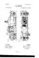
- Figure 1 is a side elevation of my improved apparatus.
- Fig. 2 is a plan view thereof; and
- Fig. 3 is a sectional view on line 33 of Fig. 1.
- A represents one of the mold frames. tom a and four sides a.
- B represents a plate which has a series of parallel half round grooves in its upper surface extending from one end to the other.
- This plate fits into the frame with a sliding fit; that is it fits as closely as it can and be adapted to be moved up and down in said frame. When this plate rests on the bottom a, the sides, a, extend above its top surface.
- eight of these molds are employed.
- To the frame of each mold four links 0 are pivoted,-two at each end; and these links are pivotally connected with similar links which are secured in like manner to the adjacent molds.
- the links and molds connected as described form an endless link belt of which every third link is a mold.
- D D represent drums secured respectively to the parallel shafts d d, which are mounted in suitable fixed bearings.
- the drums as shown are hexagonal, and are so formed to present flat surfaces against which the mold bottom may rest.
- a furnace E and a hydraulic press F which are so constructed and arranged that as the chain belt is moved, the molds are drawn through the furnace and then to the press.
- the distance between the two drums and the furnace and press is such that when one mold is resting on a horizontal face of one drum the next mold isin the furnace, the next one is in the press and the fourth mold is on one horizontal surface of the other drum.
- the pins or protuberances 1 and in the bottom a of the mold frame are holes into which these pins project automatically as the mold moves onto the drum. These pins strike against the under side of the plate B and thereby lift it until its top surface is above the top of the sides of the frame.
- H represents a shaft having two worms which engage respectively with worm wheels 01 in the ends of the shafts d d.
- the power to operate the described mechanism is applied to the shaft H.
- On the shaft are two loose pulleys h h and between them one fast pulley 72/.
- Two belts 1 I from the same counter-shaft are provided to drive the shaft H. One of the belts is crossed as shown.
- K represents a revolving brush mounted in suitable bearings.
- L represents a second revolving brush mounted just above and projecting into an oil receptacle M, the shafts of both brushes being driven by belts from the shaft of one of the drums.
- the top of the sides a are beveled outward as shown most clearly in Fig. 3.
- the left hand mold is on the drum D.
- the projections 01 have automatically raised the bottom plate above the level of the sides so that the carbons may be removed in the usual manner.
- a series of molds each consisting of a frame and a plate fitted in said frame and having a limited vertical movement therein, links pivoted to said frame, thereby connecting them all into an endless link belt and two drums over which said belt runs, combined with a furnace and a press arranged between the two drums, a table extending from one drum to the other on which the molds are supported and peripheral projections on one of the drums adapted to engage with the plates and thereby automatr cally lift them with respect to their frames, substantially as and for the purpose set forth.
Description
(No Model.) 2 SheetsSheet' I C. S. BRITTON.
CARBON MACHINE. No. 511,751. Patented Jan. 2, 1894.
o O a: o O IJ FIG.2
WITNESSES. INVENTOR.
nnnnnnnnnnnnn c.
(No Model.) 2 Sheets-Sheet 2.
O. S. -BRITTON.- CARBON MACHINE.
No. 511,751. Patented Jan, 2,1894.
FIG. 3 a M A 1 WITNESSES. IWEWTOR. M $4M 45. M4, 1 um vflwwxm UNrTnn STATES PATENT Orrrcn.
CHARLES S. BRITTON, OF CLEVELAND, OHIO.
CARBON-MACHINE.
SPECIFICATION forming part of Letterslatent No. 511,751, dated January 2, 1894;.
Application filed October 18, 1892' Serial No.44:9,222. (No model.)
To whom it may concern:
Be it known that I, CHARLES S. BRITTON, a citizen of the United States, residing at Cleveland,in the county of Ouyahoga and State of Ohio, have invented certain new and useful Improvements in Carbon-Machines; and I do hereby declare the following to be a full, clear, and exact description of the invention, such as will enable others skilled in the art to which it appertains to make and use the same.
In the modern practice of making electric light carbons, a mold is employed which consists of a bottom plate havinga series of half round grooves, a top plate having a series of corresponding grooves, and removable sides which when in place fit closely against the ends of the plates. A measured quantity of the carbon mixture is placed in the mold,- that is on the bottom plate within the sides. The mold is placed in a furnace where the mixture is heated until it becomes sufficiently plastic, when the top plate is put on and the mold is carried to a hydraulic or other powerf ul press, in which the carbons are molded by the pressure. It is necessary to make the outside frame or sides very heavy in order that they may withstand the pressure of the carbon at the ends of the grooves due to the action of the press. It is customary to construct the outside frame in such manner that it may be easily separated from the plates, and this is done for two principal reasons,first, to facilitate the removal of the top plates, and second, to free the ends of the grooves so that the carbons may be pushed lengthwise until their ends project beyond the bottom plate whereby a thin flat board may be placed under these ends and all the carbons lifted and removed together by sliding the board under them. By any other method of lifting the carbons from the mold there is great danger of bending or breaking them. This method of procedure involves the frequent lifting and carrying of the very heavymolds and is therefore objectionable. At the same time it is slow compared with the method of procedure with the mechanism hereinafter described, and likewise involves the employment of more labor.
The purpose of my invention is to provide an apparatus with which electric light carbons may be made more easily and rapidly and at less expense than with the mechanism and by the methods heretofore in use; and my invention consists in the construction and combination of parts hereinafter described and pointed out definitely in the claims.
In the drawings, Figure 1 is a side elevation of my improved apparatus. Fig. 2 is a plan view thereof; and Fig. 3 is a sectional view on line 33 of Fig. 1.
Referring to the parts by letter, A represents one of the mold frames. tom a and four sides a.
B represents a plate which has a series of parallel half round grooves in its upper surface extending from one end to the other. This plate fits into the frame with a sliding fit; that is it fits as closely as it can and be adapted to be moved up and down in said frame. When this plate rests on the bottom a, the sides, a, extend above its top surface. In the apparatus shown eight of these molds are employed. To the frame of each mold four links 0 are pivoted,-two at each end; and these links are pivotally connected with similar links which are secured in like manner to the adjacent molds. The links and molds connected as described form an endless link belt of which every third link is a mold.
D D represent drums secured respectively to the parallel shafts d d, which are mounted in suitable fixed bearings. The drums as shown are hexagonal, and are so formed to present flat surfaces against which the mold bottom may rest. Between the two drums are placed a furnace E and a hydraulic press F, which are so constructed and arranged that as the chain belt is moved, the molds are drawn through the furnace and then to the press. The distance between the two drums and the furnace and press is such that when one mold is resting on a horizontal face of one drum the next mold isin the furnace, the next one is in the press and the fourth mold is on one horizontal surface of the other drum.
Extending from one drum to the other is a table G on which the molds rest and slide in moving forward. Thefloor of the furnace is It has a bota part of this table, and so also is the platen of the press.
Projecting from the surfaces of the drum D on which the molds rest are the pins or protuberances 1 and in the bottom a of the mold frame are holes into which these pins project automatically as the mold moves onto the drum. These pins strike against the under side of the plate B and thereby lift it until its top surface is above the top of the sides of the frame.
H represents a shaft having two worms which engage respectively with worm wheels 01 in the ends of the shafts d d. The power to operate the described mechanism is applied to the shaft H. On the shaft are two loose pulleys h h and between them one fast pulley 72/. Two belts 1 I from the same counter-shaft are provided to drive the shaft H. One of the belts is crossed as shown.
J represents a belt shifter by means of which either belt may be moved onto the fast pulley and thereby the shaft H may be driven in either direction.
K represents a revolving brush mounted in suitable bearings.
L represents a second revolving brush mounted just above and projecting into an oil receptacle M, the shafts of both brushes being driven by belts from the shaft of one of the drums.
WV hen the several molds are in the position shown in the drawings, a measured quantity of the carbon material is placed in the right hand mold. The next mold to the left is in the furnace where the material therein is being renderedplastic enough to be molded in the press.
In order to hold the heat in the furnace, I provide swinging doors 6 e pivoted at their top edges (shown by dotted lines in Fig. 1). As the mold enters or leaves the furnace, it pushes back these doors, which, when the mold has passed, swing automatically to place and close the openings. The next mold is in the press by which the carbons are pressed into shape between the plate B and plate N which is permanently fastened to the press, and is provided with a series of half round grooves which correspond with the grooves in the plate 13. A pipe a may be employed which surrounds and lies close to the edge of the plate N, and steam may be forced through the pipe, thereby heating the plate N, so that it will not chill the carbon material in the mold when brought in contact therewith.
In order to secure the proper entry of the top plate N into the mold frame, the top of the sides a are beveled outward as shown most clearly in Fig. 3. The left hand mold is on the drum D. The projections 01 have automatically raised the bottom plate above the level of the sides so that the carbons may be removed in the usual manner. When the several operations above described are completed, theproper belt is shifted to the fastpulley h, the drums D D are revolved until the molds are drawnforwardtothe nextposit on,- that is to say until the mold just filled is in the furnace, and the mold which was in the furnaoe is in the press, &c., when the mechanism is again stopped, and the press set in motion. Inmoving forward, the lower molds, which are returning to the filling point, are upside down; the plates B are kept from falling out by means of the pins b which are fastened to the frame and project into grooves in sides of the plate B. As a mold moves over the brush K, the plate B is brushed clean, and as it moves over the brush 1t 1s oiled so that the carbon material will not stick to it.
Having described my invention, I claim?- 1. In an apparatus for making electric light carbons, an endless link belt, a series of molds arranged at suitable intervals connected in and forming a part of said belt, two drums around which said belt runs and by which it is driven, and mechan sm for revolving said drums, combined with a furnace, and a press arranged between the two drums, and a table extending from one drum to the other on which the molds are supported, substantially as and for the purpose specified.
2. In an apparatus for making electric light carbons, a series of molds each consisting of a frame and a plate fitted in said frame and having a limited vertical movement therein, links pivoted to said frame, thereby connecting them all into an endless link belt and two drums over which said belt runs, combined with a furnace and a press arranged between the two drums, a table extending from one drum to the other on which the molds are supported and peripheral projections on one of the drums adapted to engage with the plates and thereby automatr cally lift them with respect to their frames, substantially as and for the purpose set forth.
3. In an apparatus for making electric light carbons, a series of molds connected by links and forming with them an endless belt, two parallel drums, and means for revolving them intermittently, combined witl a furnace, a press, a table, a revolving cleaning brush, and a revolving oiling brush, substantially as and for the purpose specified.
4.- In an apparatus for making electric light carbons, a series of molds, links 0on meeting said molds and forming. with them an endless belt, two parallel drums and mechanism for revolving them intermittently,
IIO
combined with furnace doors to said furnace molds successively into said press, substantially as and for the purpose set forth.
In testimony whereof I affix my signature in presence of two Witnesses.
CHARLES S. BRITTON.
lVitnesses:
E. L. THURSTON, FRANCIS J. WING,
Publications (1)
| Publication Number | Publication Date |
|---|---|
| US511751A true US511751A (en) | 1894-01-02 |
Family
ID=2580573
Family Applications (1)
| Application Number | Title | Priority Date | Filing Date |
|---|---|---|---|
| US511751D Expired - Lifetime US511751A (en) | Carbon-machine |
Country Status (1)
| Country | Link |
|---|---|
| US (1) | US511751A (en) |
Cited By (2)
| Publication number | Priority date | Publication date | Assignee | Title |
|---|---|---|---|---|
| US2447415A (en) * | 1944-07-05 | 1948-08-17 | Lyon George Albert | Plastic forming apparatus and method |
| US2958901A (en) * | 1960-11-08 | Molla |
-
0
- US US511751D patent/US511751A/en not_active Expired - Lifetime
Cited By (2)
| Publication number | Priority date | Publication date | Assignee | Title |
|---|---|---|---|---|
| US2958901A (en) * | 1960-11-08 | Molla | ||
| US2447415A (en) * | 1944-07-05 | 1948-08-17 | Lyon George Albert | Plastic forming apparatus and method |
Similar Documents
| Publication | Publication Date | Title |
|---|---|---|
| US511751A (en) | Carbon-machine | |
| US1453746A (en) | Process of making concrete blocks | |
| US1185399A (en) | Machine for molding from cement and other plastic materials. | |
| US978233A (en) | Dough-molding machine. | |
| US395095A (en) | Machine for making multitubular pipe | |
| US701386A (en) | Machine for japanning small articles. | |
| US1825938A (en) | Brick embossing machine | |
| US646266A (en) | Apparatus for pickling or cleaning metal sheets. | |
| US271875A (en) | le poidevin | |
| US505775A (en) | marks | |
| USRE16076E (en) | Soap-molding machine | |
| US60050A (en) | Improved brick machine | |
| US743972A (en) | Machine for making pasted leather stock. | |
| US858940A (en) | Brushing-machine. | |
| US303814A (en) | Machine for the manufacture of school-crayons | |
| US513986A (en) | Pill-machine | |
| US616322A (en) | hatteberg | |
| US332474A (en) | Brick-machine | |
| US636560A (en) | Brick-making machine. | |
| US837364A (en) | Coke-leveling machine. | |
| US999623A (en) | Machine for grooving railway-sleepers. | |
| US697322A (en) | Can-steaming machine. | |
| US796640A (en) | Molding machine or apparatus. | |
| US738114A (en) | Charging-machine. | |
| US796668A (en) | Dyeing apparatus. |