US511652A - Motor for cars or other purposes - Google Patents
Motor for cars or other purposes Download PDFInfo
- Publication number
- US511652A US511652A US511652DA US511652A US 511652 A US511652 A US 511652A US 511652D A US511652D A US 511652DA US 511652 A US511652 A US 511652A
- Authority
- US
- United States
- Prior art keywords
- piston
- cylinder
- openings
- rod
- arm
- Prior art date
- Legal status (The legal status is an assumption and is not a legal conclusion. Google has not performed a legal analysis and makes no representation as to the accuracy of the status listed.)
- Expired - Lifetime
Links
- 241000239290 Araneae Species 0.000 description 17
- 238000005266 casting Methods 0.000 description 8
- 150000001875 compounds Chemical class 0.000 description 7
- 239000011435 rock Substances 0.000 description 6
- 238000002485 combustion reaction Methods 0.000 description 3
- 238000010276 construction Methods 0.000 description 3
- MPDDTAJMJCESGV-CTUHWIOQSA-M (3r,5r)-7-[2-(4-fluorophenyl)-5-[methyl-[(1r)-1-phenylethyl]carbamoyl]-4-propan-2-ylpyrazol-3-yl]-3,5-dihydroxyheptanoate Chemical compound C1([C@@H](C)N(C)C(=O)C2=NN(C(CC[C@@H](O)C[C@@H](O)CC([O-])=O)=C2C(C)C)C=2C=CC(F)=CC=2)=CC=CC=C1 MPDDTAJMJCESGV-CTUHWIOQSA-M 0.000 description 1
- 238000004880 explosion Methods 0.000 description 1
- 239000000203 mixture Substances 0.000 description 1
- 238000005507 spraying Methods 0.000 description 1
Images


Classifications
-
- F—MECHANICAL ENGINEERING; LIGHTING; HEATING; WEAPONS; BLASTING
- F02—COMBUSTION ENGINES; HOT-GAS OR COMBUSTION-PRODUCT ENGINE PLANTS
- F02B—INTERNAL-COMBUSTION PISTON ENGINES; COMBUSTION ENGINES IN GENERAL
- F02B25/00—Engines characterised by using fresh charge for scavenging cylinders
Definitions
- DAVID SANDERS OF ⁇ VILLIAMSPORT, PENNSYLVANIA.
- Fig. 11 is for Cars or other Purposes, of which the an enlarged detail sectional horizontal view following specification, taken'in connection of a portion of the transmitting mechanism with the accompanying drawings, is a full, and compound clutch.
- 1 is a truck frame of any approved con- My invention consists of an improved form struction mounted on the axles 2 by means of air and gas engine and is represented as of axle boxes 3, which axles are provided with applied to a car and geared through suitable track wheels 4. transmitting mechanism to the axles. 5 and 5 are sprocket'wheels keyed respect- IS The air and gas engine consists essentially ively to the front and rear axles 2.
- each piston being provided with cylinder of my improved compound cylinder an automatic rotary valve of peculiar conengine, which is supported upon cross-beams 7o struction allowing for the exhaust through 8 and 9 of the truck frame.
- Each of these 20 the pistons.
- the piston rod is guided at its cylinders is provided in its outer head 10 with' center between the two cylinders by a suita circular opening 11 in which is supported able cross-head which worksin suitable guidea cylindrical casting 12 formed with a series ways.
- I also provide compound friction gear of circular openings and suitable bearings 13 for transmitting the power from the engine and 1 1 for the reciprocation of the valve rod 2 5 at a slow or rapid rate.
- the power is gener- 15 of the automatic valve 16.
- Fig-ure 1 is a top plan motor. view of a car truck having my improved mo- 19 is an oil pipe of smaller diameter than 0 tor applied thereto. Fig.
- Fig. 1 is an enlarged horizonoil pipe 19 and controlled by suitable auto- 5 tal sectional view of the double cylinder and matic mechanism to be hereinafter described.
- Fig. 5 pistons.
- Fig. 5 is a vertical sectional view
- the oil pipe 19 leads from the tank 22 supof the same.
- Fig. 6 is a face view of one of ported in any suitable position on the truck the pistons.
- Fig. 7 is a detail longitudinal frame, for supplying oil to the engine.
- the sectional view representing the preferred form oil pipe 19 of course divides under the cylintoo of braking mechanism.
- Fig.8 is an enlarged der 7 to lead to both ends of the compound 50 sectional detailview illustrating the arrange cylinder.
- crank shaft supported in suitable clutch, and opening the cooks in the oil pipes.
- bearings 24 and provided at its opposite ends Fig. 9 is an inner enlarged end view of the with crank arms 25 which are keyed to the shaft.
- crank arm 26 is a crank arm extending from the stop cook 21 in each of the oil pipes 19, and 27 is a link connecting each of the crank arms 25 with one of the crank arms 26, whereby, when the rock shaft 23 is rotated in its bearings both of said stop cocks 21 in the oil pipes 19 will be actuated simultaneouslyto open or cutoff the supply of oil.
- crank arm 28 extends up fromthe rock shaft 23 and is keyed thereto.
- each of the cylinders 6, 7, which are secured together to form the compound cylinder are provided with inner ends or heads 35 and 36 respectively, and through the central openings in said heads 35 and 36 the piston rod37 reciprocates.
- each of the opposite ends of the piston rod 37 is one of my automatic pistons.
- the extreme ends of said piston rod 37 are contracted at 44 to form shoulders 45.
- the head 46 is a piston head formed with a series of circular openings 47 and a central circular depression 48 on its outer face.
- the head 46 is adapted to fit on the contracted end 44 ofthe piston rod and is secured thereon from rotation by any suitable means.
- 49 is a collar mounted 011 the end of the piston rod outside of the piston head, and adapted to rotate freely thereon.
- a circular rotatable valve plate formed with a central perforated circular boss 51 adapted to fit over the collar 49 and rest in the central depression 48 of the piston head, and also provided with a series of circular I openings adapted to register With the openings in the piston head for allowing the exhaust of the products of combustion therethrough.
- the spider 53 is a double rotary arm or spider formed With an enlarged central portion having an opening therethrough for the passage of the piston rod, upon which the spider rotates.
- the spider is adapted to work on the piston rod close up against the piston head, and the two arms curve outwardly from the enlarged central supporting portion and pass through the circular exhaust openings of the piston head and are secured to the rotating valve plate in any suitable manner.
- spiral spring 54 is a spiral spring encircling the piston rod and having one end attached to the rod and the other end engaging one of the arms of the rotatable spider. spiral spring is for holding the spider and rotatable valvein their normal position for closing the exhaust openings through the piston head.
- '57 is a small post extending up froin'the bottom of the cylinder 6 adjacent to the head 35, and'58 is an arm journaled to the upper end of said post 57 and having a limited rotary movement thereon.
- the arm 58 is formed with a beveled nose 59.
- 60 is a spiral spring surrounding the post 57 and secured thereto at one end, and engaging the underside ofthe arm 58 at its opposite end to hold said arm in its normal po-' sition with yielding pressure.
- 61 is a beveled cam projection extending from the inner face of the head 35just above the arm 58 and in the same plane as the arm 55.
- each of the cylinders 6, 7, is a small opening in the under side of each of the cylinders 6, 7, for the admission of the flame which ignites the combined oil and air.
- .63 is a rotatable circular plate formed with a series of circular openings adapted to register with the opening 62.
- the 64 is a small lamp or other burner for supplying fiame, supported directly under the opening 62, so that when the plate 63 is rotated, by means presently to be described, the flame will be admitted to the combustion chamber of the cylinder every time one of the openings of the rotary plate registers with the opening 62 into the cylinder.
- Each of the rotatable plates 63 is supported from the cylinder by means of a journal bolt 65 and is formed on its periphery with a series of notches or ratchets 66.
- 67 is a longitudinally movable rod formed on its opposite ends with a pair of pawls 68 which engage in the ratchets of the rotatable plates 63 for rotating them when the rod is moved longitudinally.
- 69 and 70 are lugs projecting from the side of the rod 67
- 71 is an arm formed on the inner face of the cross head 38 in line with the lugs 69 and 70 and adapted to engage them alternately for moving the rod 67 to and fro and shifting the plates 63 for allowing the flame to enter the combustion chambers alternately.
- 73 and 74 are castings mounted upon and supported between crossbars 72 and 8 and provided with journal boxes 74 7t and 75, 75- for supporting respectively the power shafts 76 and the driven shaft 77.
- 78 is a crank arm keyed to the end of the power shaft 76, and 79 is a link having a divided end 80 which is journaled to the crosshead 38 as clearly shown in Fig. 1.
- 81 is a small cog wheel meshing with a large cog wheel 82 loosely mounted on the driven shaft 77
- 83 is a large cog wheel keyed to the power shaft 76 and meshing with a smaller cog wheel 84 also loosely mounted on the shaft 77.
- the inner face of the cog wheel 82 is formed with a cone shaped recess 86 to form .iuafter explained.
- the compound clutch block 88 is formed with a central annular groove 91 in which are located two semi-circular bars 92 formed with pivoted pins 93 projecting from their outer faces.
- 94 and 95 are sections of a clutch shifting lever which have their forward ends curved approximately concentric to the portion of the clutch block 88, and are pivotally connected to the pins 93 of the bars 92.
- the clutch shifting lever is pivoted to the frame at 96 and hasarearwardly extending arm 97.
- 96 is a bracing rod extending from the pivot 96 to the cross-bar 8.
- 98 is a crank arm keyed to the pin 32 above the chain wheel 30, andpivotally attached at its outer end to the arm 97 of the clutch shifting lever, by means of a pin 99.
- the 102 is an indicator secured to the dash of the car, and having one end of the cord 100 connected to it, whereby the position of the clutch shifting lever and the oil cocks is indicated.
- the cord 100 passes over suitable end of the car.
- 103 and 104 are arms projecting from the clutch shifting lever, and 105 are chains or ropes attached to the ends of the levers and extending to the opposite ends of the car where they are attached to oppositely extending crank arms 106 and 107 formed integral with the rock shaft 108which is journaled in a bracket 109.
- 111 and 112 are a pair of small sprocket wheels keyed to the driven shaft 77 alongside of the cog wheel 84 and 113' and 114 are sprocket chains passing around said sprocket wheels 111 and 112 and the sprocket Wheels 5, 5 respectively on the axles 2', 2.
- 115 is a curved brace extending between the cross-bars 72 and 8 under the friction pulley 91.
- 116 is a block secured to the brace 115 by means of a bolt 117 and having an opening 118 through it.
- One end of an ordinary band brake 119 is secured to said block 116 and passed around the friction pulley 91 as shown clearly in Fig.- 7.
- 122- and 123 are guide pulleys over which extend brake chains 124: and 125 said brake chains being attached to the chain 120 and passed over said pulleys 122 and 123 to the opposite ends of the car.
- Pivoted to the platform of the car is a lever 126 which extends beneath thereof and to the lower endof which lever one of the brake chains is attached.
- a motive power engine comprising a cylinder having supply and exhaust openings, a piston working in the cylinder and having exhaust openings through it, a rotatable valve plate carried by the piston and having openings which are adapted to control the exhaust openings through the piston, and means for automatically operating said valve plate, as. set forth.
- a motive power engine comprising a cylinder, a valved opening on one end of the cylinder, means for supplying mixed air and oil, to said opening means for igniting the mixture in the cylinder, a piston working in said cylinder, exhaust openingsthrough the through the piston, means for holding the valve platein normal position for closing the openings through the piston, and means for rotating said valve platefor opening the exhaust through said piston, substantially as set forth.
- a motive p was engine comprising a cylinder having supply and exhaust openings, a piston and piston-rod working in the cylinder, exhaust openings through the piston, a rotatable valve plate having openings adapted to register with the openings through the piston, a spiral spring for holding the valve plate normally in closed position, and means for rotating the plate against the actionof the spring for opening the exhaust through the piston, substantially as set forth.
- a motive power engine comprising a cylinder having supply and exhaust openings, a piston and piston-rod working in said cylinder, exhaust openings through the piston, a
- rotatable valve plate adapted to close the openings through the piston, a spider rotatably mounted on the piston-rod and engaging the rotatable valve plate, a spiral spring ongaging the piston-rodand spider for holding the spider and rotatable valve plate in their normal position, and means for rotating the spider for opening the exhaust through the piston, substantially as set forth.
- a motive power engine comprising a 03 1-, inder supply and exhaust openings, a piston and piston-rod working in said cylinder, exhaust openings through the piston, a rotatable valve plate mounted on the piston-rod adjacent to the piston, a spider also rotatably mounted on the piston-rod and engaging the valve plate, a spring for holding the spider and valve plate in normal position, an arm projecting from the spider, and a cam on the inside of the cylinder adapted to engage said arm for operating the valve plate against the action of the spring, substantially as set forth.
- a motive power engine comprising a cylinder having supply and exhaust openings, a
- Amotive power engine comprising a cyl- 1n der having supply and exhaust openings, a piston and piston-rod working in said cylin- 1nder, exhaust openings through the piston, a valve plate rotatably supported on the pistonrod and adapted to control the exhaust openings through the piston, a spider rotatably mounted on the piston-rod and engaging the valve plate, a spiral spring engaging the piston and spider, an arm projecting from the spider and having a depending nose, a spring latch pivotally supported from the cylinder and a cam shaped projection extending from the inner head of the cylinder, substantially as and for the purpose set forth.
- Amotive power engine comprising two cylinders supported end to end,independent supply and exhaust openings in said cylinders,means for supplying mingled oil and air to the outer end of each cylinder, pistons in said cylinders, having exhaust openings therethrough, a piston-rod joining said pistons, a cross-head on said piston-rod, a flame opening in the bottom of each cylinder, rotatable plates having series of openings adapted to register with the flame openings, flames under the flame openings, ratchets on said rotatable plates, a longitudinally movable rod engaging the ratchets of said rotatable plates,
Landscapes
- Engineering & Computer Science (AREA)
- Chemical & Material Sciences (AREA)
- Combustion & Propulsion (AREA)
- Mechanical Engineering (AREA)
- General Engineering & Computer Science (AREA)
- Output Control And Ontrol Of Special Type Engine (AREA)
Description
(No Model.) I 5 Sheets-Sheet 1.
' D. P. SANDERS.
MOTOR FOR CARS OR OTHER PURPOSES. No. 511,652. Patented Dec. 26, 1893.
YHB NAYIONAL umomumma CQMPANV.
wAsumeToN. o c;
(No ModeL) 5 Sheets-Sheet 2.
D. P. SANDERS. MOTOR FOR CARS OR OTHER PURPOSES. N0. 511,652. R Patented Dec. 26, 1893.
fnverzfo?" DQMPSQNCYQKS.
( o 5 Sheets-Sheet 3. D. P. SANDERS. MOTOR FOR CARS OR OTHER PURPOSES.
Patented Dec. 26, 1893.
(No Model.)
D. P. SANDERS. MOTOR P OR GARS QR OTHER PURPOSES. No. 511,652.
5 Sheets-Sheet 4,
" Patented Dec. 26, 1893.
/71ve71 far .Davz'd BSarnYers.
(No Model.) 5 Sheets-Sheet 5.
D. P. SANDERS.
MOTOR FOR CARS OR OTHER PURPOSES. N0. 511,652.v Patented Dec. 26, 1893 UNITED STAT S PATENT @nnres.
DAVID SANDERS, OF \VILLIAMSPORT, PENNSYLVANIA.
MOTOR FOR CARS OR OTHER PURPOSES.
SPECIFICATION forming part of Letters Patent No. 511,652, dated December 26, 1893. Application filed June 24, 1892. Serial No. 437,871. (No model.)
To all whom it may concern;
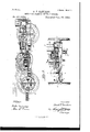
Be it known that I, DAVID P. SANDERS, a casting secured to the end of the cylinder. citizen of the United States, residing at WVil- Fig. is an enlarged detail sectional View liamsport, in the county of Lycoming and illustrating the construction of the opening 5 State of Pennsylvania, have invented a cerinto the end of the cylinder and automatic tain new and useful Improvement in Motors valve which guards the opening. Fig. 11 is for Cars or other Purposes, of which the an enlarged detail sectional horizontal view following specification, taken'in connection of a portion of the transmitting mechanism with the accompanying drawings, is a full, and compound clutch.
10 clear, and exact description. 1 is a truck frame of any approved con- My invention consists of an improved form struction mounted on the axles 2 by means of air and gas engine and is represented as of axle boxes 3, which axles are provided with applied to a car and geared through suitable track wheels 4. transmitting mechanism to the axles. 5 and 5 are sprocket'wheels keyed respect- IS The air and gas engine consists essentially ively to the front and rear axles 2.
of a double cylinder in which operates adou- 6 is the forward cylinder and 7 is the rear ble piston, each piston being provided with cylinder of my improved compound cylinder an automatic rotary valve of peculiar conengine, which is supported upon cross-beams 7o struction allowing for the exhaust through 8 and 9 of the truck frame. Each of these 20 the pistons. The piston rod is guided at its cylinders is provided in its outer head 10 with' center between the two cylinders by a suita circular opening 11 in which is supported able cross-head which worksin suitable guidea cylindrical casting 12 formed with a series ways. I also provide compound friction gear of circular openings and suitable bearings 13 for transmitting the power from the engine and 1 1 for the reciprocation of the valve rod 2 5 at a slow or rapid rate. The power is gener- 15 of the automatic valve 16. These circular ated from'gasoline orother suitable oilinteropenings through the casting 12 first conmingled with air and fed into the outer ends verge inwardly to the central valve chamber of the cylinders to form a combustible gas, and then outwardly into the cylinder for the So which when ignited by a suitable flame expurpose of spraying the mixed oil and air.
0 plodes and operates the pistons, in a manner The inner central opening of the casting 12 well understood in the art. is formed with conical walls to form the proper In orderthat myinvention may be fully unseat for the conical valve 16. derstood I will first describe the same with 17 is a pipe joint secured onto the projectreference to the accompanying drawings, and ing end of the casting 12, and 18 is a section 5 will then more particnlarlydefinein theclaims of pipe leading from said joint 17 to any suitthe novel features. able position and adapted to supply air to the In said draWings:Fig-ure 1 is a top plan motor. view of a car truck having my improved mo- 19 is an oil pipe of smaller diameter than 0 tor applied thereto. Fig. 2 is a longitudinal the air pipe 18 and entering said air pipe 20 4o sectional view of the same taken on the line and extending up to a point a little below the 22 of Figs. 2 and 3. Fig. 3 is a rear end casting 12. elevation, part of the truck frame being 21 is a rotating stop cock inserted in the broken away. Fig. 1 is an enlarged horizonoil pipe 19 and controlled by suitable auto- 5 tal sectional view of the double cylinder and matic mechanism to be hereinafter described.
5 pistons. Fig. 5 is a vertical sectional view The oil pipe 19 leads from the tank 22 supof the same. Fig. 6 is a face view of one of ported in any suitable position on the truck the pistons. Fig. 7 is a detail longitudinal frame, for supplying oil to the engine. The sectional view representing the preferred form oil pipe 19 of course divides under the cylintoo of braking mechanism. Fig.8 is an enlarged der 7 to lead to both ends of the compound 50 sectional detailview illustrating the arrange cylinder.
ment of levers for operating thecompound 23 is a "crank shaft supported in suitable clutch, and opening the cooks in the oil pipes. bearings 24 and provided at its opposite ends Fig. 9 is an inner enlarged end view of the with crank arms 25 which are keyed to the shaft. g
26 is a crank arm extending from the stop cook 21 in each of the oil pipes 19, and 27 isa link connecting each of the crank arms 25 with one of the crank arms 26, whereby, when the rock shaft 23 is rotated in its bearings both of said stop cocks 21 in the oil pipes 19 will be actuated simultaneouslyto open or cutoff the supply of oil. Between the bearings 24 a crank arm 28 extends up fromthe rock shaft 23 and is keyed thereto.
29 is an endless chain attached to the upper end of the crank arm 28 and passing around and also attached to a chain wheel '30 which is keyed to a pin 32 rotatably supported upon a projection 33 of the cross-bar 80f the truck frame. This chain Wheel is operated for opening and closing the oil cocks in a manner hereinafter to be described.
Referring particularly to Figs. 4, 5, and 6 I will now describe the construction of the pistons and connecting piston rod which work in the compound cylinder. Each of the cylinders 6, 7, which are secured together to form the compound cylinder are provided with inner ends or heads 35 and 36 respectively, and through the central openings in said heads 35 and 36 the piston rod37 reciprocates.
38 is across-head keyed to the center'of the piston rod 37 and having the vertically projecting bearing rods 39.
40 and 41 are guide pieces secured to the adjacent ends of the cylinders 6, 7, and forming tracks for the reciprocation of the guide blocks 42 which are secured to the outer ends of the rods 39.
43 is an exhaust opening in the upper wall of each cylinder 6, 7, near their inner ends.
Attached to each of the opposite ends of the piston rod 37 is one of my automatic pistons. The extreme ends of said piston rod 37 are contracted at 44 to form shoulders 45.
46 is a piston head formed with a series of circular openings 47 and a central circular depression 48 on its outer face. The head 46is adapted to fit on the contracted end 44 ofthe piston rod and is secured thereon from rotation by any suitable means.
49 is a collar mounted 011 the end of the piston rod outside of the piston head, and adapted to rotate freely thereon.
50 is a circular rotatable valve plate formed with a central perforated circular boss 51 adapted to fit over the collar 49 and rest in the central depression 48 of the piston head, and also provided with a series of circular I openings adapted to register With the openings in the piston head for allowing the exhaust of the products of combustion therethrough.
52 is a screw nut engaging the extreme out-- er end of the piston rod for holding the parts of the improved piston in place.
53 is a double rotary arm or spider formed With an enlarged central portion having an opening therethrough for the passage of the piston rod, upon which the spider rotates. The spider is adapted to work on the piston rod close up against the piston head, and the two arms curve outwardly from the enlarged central supporting portion and pass through the circular exhaust openings of the piston head and are secured to the rotating valve plate in any suitable manner.
54 is a spiral spring encircling the piston rod and having one end attached to the rod and the other end engaging one of the arms of the rotatable spider. spiral spring is for holding the spider and rotatable valvein their normal position for closing the exhaust openings through the piston head.
55 is a rearwardly projecting arm formed integral with the lower arm of the spider 53 and provided with a downwardly projecting nose 56. The outerface of the end of the arm 55 and the nose 56 are beveled off for the purpose presently to appear. I
'57 is a small post extending up froin'the bottom of the cylinder 6 adjacent to the head 35, and'58 is an arm journaled to the upper end of said post 57 and having a limited rotary movement thereon. The arm 58 is formed with a beveled nose 59.
60 is a spiral spring surrounding the post 57 and secured thereto at one end, and engaging the underside ofthe arm 58 at its opposite end to hold said arm in its normal po-' sition with yielding pressure.
61 is a beveled cam projection extending from the inner face of the head 35just above the arm 58 and in the same plane as the arm 55.
When the piston is forced rearwardly by the expansion of the exploded gas the rotatable valve plate 50 is in its normal position to close the exhaust ports through the piston head, and as the arm 55 comes in contact with the cam 61 it is forced to one side as indicated in dotted lines in Fig, 5 which action rotates the valve platev through the medium of the rotatable spider and thereby opens the exhaust openings through the piston head and allows the products of the explosion to exhaust therefrom into the inner end of the cylinder and out through the exhaust opening at the top. At the same time that the arm 55 is forced to one side by coming in contact with the cam projection 61, the nose 56 engages the arm 58 and forces it to one side, also as indicated in dotted lines in Fig. 5, and as soon as the nose 56 has passed out of engagement with said arm 58, the spiral spring 60 forces said arm back into its normal position as indicated in full lines in Fig. 5: at this point the pistons are ready to take their return stroke and the nose 56 engages the side of the arm 58 which is held from rotation in the opposite direction andthereby the valveplate 50 will be held in its open rotated position until the piston has receded so far that the nose 56 can slip'off of the rounded rear end The office of the too of the arm 58 and allow the spiral spring 54: to force the valve plate back into its normal position to close the valves through the piston head.
62 is a small opening in the under side of each of the cylinders 6, 7, for the admission of the flame which ignites the combined oil and air.
.63 is a rotatable circular plate formed with a series of circular openings adapted to register with the opening 62.
64 is a small lamp or other burner for supplying fiame, supported directly under the opening 62, so that when the plate 63 is rotated, by means presently to be described, the flame will be admitted to the combustion chamber of the cylinder every time one of the openings of the rotary plate registers with the opening 62 into the cylinder.
Each of the rotatable plates 63 is supported from the cylinder by means of a journal bolt 65 and is formed on its periphery witha series of notches or ratchets 66.
67 is a longitudinally movable rod formed on its opposite ends with a pair of pawls 68 which engage in the ratchets of the rotatable plates 63 for rotating them when the rod is moved longitudinally.
69 and 70 are lugs projecting from the side of the rod 67, and 71 is an arm formed on the inner face of the cross head 38 in line with the lugs 69 and 70 and adapted to engage them alternately for moving the rod 67 to and fro and shifting the plates 63 for allowing the flame to enter the combustion chambers alternately.
I have described only one end of the double cylinder and. piston and operating mechanism but it will be clear that both ends are similarly constructed and need not further be described.
72 is another cross bar of the truck frame between which and the cross-bar 8 the transmitting mechanism is supported.
73 and 74 are castings mounted upon and supported between crossbars 72 and 8 and provided with journal boxes 74 7t and 75, 75- for supporting respectively the power shafts 76 and the driven shaft 77.
78 is a crank arm keyed to the end of the power shaft 76, and 79 is a link having a divided end 80 which is journaled to the crosshead 38 as clearly shown in Fig. 1.
81 is a small cog wheel meshing with a large cog wheel 82 loosely mounted on the driven shaft 77, and 83 is a large cog wheel keyed to the power shaft 76 and meshing with a smaller cog wheel 84 also loosely mounted on the shaft 77.
85 is a fly wheel also keyed to the power shaft 76. The inner face of the cog wheel 82 is formed with a cone shaped recess 86 to form .iuafter explained.
88 is a compound clutch formed with the large clutch face 89 and the small clutch face 90 which are adapted to engage respectively the members 86 and 87. This clutchissplined to the driven shaft 77 and is adapted to move longitudinally thereon for engaging with either one of the said wheels, which are loosely mounted on the shaft.
91 is a friction pulley formed integral with the clutch 88 and adapted to receive a friction band which operates as a brake, as here- The compound clutch block 88 is formed with a central annular groove 91 in which are located two semi-circular bars 92 formed with pivoted pins 93 projecting from their outer faces. 94 and 95 are sections of a clutch shifting lever which have their forward ends curved approximately concentric to the portion of the clutch block 88, and are pivotally connected to the pins 93 of the bars 92. The clutch shifting lever is pivoted to the frame at 96 and hasarearwardly extending arm 97. 96 is a bracing rod extending from the pivot 96 to the cross-bar 8. 98 is a crank arm keyed to the pin 32 above the chain wheel 30, andpivotally attached at its outer end to the arm 97 of the clutch shifting lever, by means of a pin 99.
100 is a wire cord attached to the pin 99 and extending to the opposite ends of the platform 101 of'the car. I
102 is an indicator secured to the dash of the car, and having one end of the cord 100 connected to it, whereby the position of the clutch shifting lever and the oil cocks is indicated. The cord 100 passes over suitable end of the car.
103 and 104 are arms projecting from the clutch shifting lever, and 105 are chains or ropes attached to the ends of the levers and extending to the opposite ends of the car where they are attached to oppositely extending crank arms 106 and 107 formed integral with the rock shaft 108which is journaled in a bracket 109.
110 is the operating hand lever which is keyed to the rock shaft 108. This arrangement will be clear from Figs. 1 and 7.
It will be observed that when the clutch block 88 is moved to its central position the driven shaft will remain still and allow the power shaft and the cog wheels geared thereto IIO to revolve,'and at the same time the position of from the reservoir or tank and drops out into the air pipe where the air takes it up and it is sucked in to the end of the cylinder by the movement of the piston, and owing to the conical shape of the casting 12 and the valve 16 the commingled oil and air will be sprayed into the cylinder. When sufficient quantity of thegas has been admitted, the movement of the revolving plate allows the flame to ignite and explode the gas which forces the pis ton forward in a manner well understood. The action of the'pistons has already been explained.
111 and 112 are a pair of small sprocket wheels keyed to the driven shaft 77 alongside of the cog wheel 84 and 113' and 114 are sprocket chains passing around said sprocket wheels 111 and 112 and the sprocket Wheels 5, 5 respectively on the axles 2', 2.
115 is a curved brace extending between the cross-bars 72 and 8 under the friction pulley 91.
116 is a block secured to the brace 115 by means of a bolt 117 and having an opening 118 through it. One end of an ordinary band brake 119 is secured to said block 116 and passed around the friction pulley 91 as shown clearly in Fig.- 7.
120 is a brake chain or rope attached to'the' band 119 and passing through the opening 118 of the block 116 and around a pulley 121.
122- and 123 are guide pulleys over which extend brake chains 124: and 125 said brake chains being attached to the chain 120 and passed over said pulleys 122 and 123 to the opposite ends of the car. Pivoted to the platform of the car is a lever 126 which extends beneath thereof and to the lower endof which lever one of the brake chains is attached.
One of said brake levers is applied to each,
end of the platform of the car. By this means the car can be very successfully stopped after the clutch has been disengaged, and the supply of oil out off, for it will be observed that the friction pulley is in direct connection with the wheels of the car through the sprocket Wheels and chains.
By my improvements I am enabled to provide a motor car of such construction that engines of small power may be used successfully and with a large saving of expense as com pared with the present use of electric and cable lines in street railways.
Having thus fully described my invention, what'I claim as new therein, and desire to secure by Letters Patent, is- I 1. A motive power engine comprising a cylinder having supply and exhaust openings, a piston working in the cylinder and having exhaust openings through it, a rotatable valve plate carried by the piston and having openings which are adapted to control the exhaust openings through the piston, and means for automatically operating said valve plate, as. set forth.
2. A motive power engine comprising a cylinder, a valved opening on one end of the cylinder, means for supplying mixed air and oil, to said opening means for igniting the mixture in the cylinder, a piston working in said cylinder, exhaust openingsthrough the through the piston, means for holding the valve platein normal position for closing the openings through the piston, and means for rotating said valve platefor opening the exhaust through said piston, substantially as set forth.
4:. A motive p wer engine,- comprising a cylinder having supply and exhaust openings,a piston and piston-rod working in the cylinder, exhaust openings through the piston, a rotatable valve plate having openings adapted to register with the openings through the piston, a spiral spring for holding the valve plate normally in closed position, and means for rotating the plate against the actionof the spring for opening the exhaust through the piston, substantially as set forth.
5. A motive power engine,- comprisinga cylinder having supply and exhaust openings, a piston and piston-rod working in said cylinder, exhaust openings through the piston, a
rotatable valve plate adapted to close the openings through the piston, a spider rotatably mounted on the piston-rod and engaging the rotatable valve plate, a spiral spring ongaging the piston-rodand spider for holding the spider and rotatable valve plate in their normal position, and means for rotating the spider for opening the exhaust through the piston, substantially as set forth.
6. A motive power engine, comprising a 03 1-, inder supply and exhaust openings, a piston and piston-rod working in said cylinder, exhaust openings through the piston, a rotatable valve plate mounted on the piston-rod adjacent to the piston, a spider also rotatably mounted on the piston-rod and engaging the valve plate, a spring for holding the spider and valve plate in normal position, an arm projecting from the spider, and a cam on the inside of the cylinder adapted to engage said arm for operating the valve plate against the action of the spring, substantially as set forth.
7. A motive power engine comprising a cylinder having supply and exhaust openings, a
and a cam projecting from the cylinder,
whereby the exhaust through the piston will be opened at the proper moment and held open during. a portion of the return stroke of the piston, as set forth.
S. Amotive power engine comprising a cyl- 1n der having supply and exhaust openings, a piston and piston-rod working in said cylin- 1nder, exhaust openings through the piston, a valve plate rotatably supported on the pistonrod and adapted to control the exhaust openings through the piston, a spider rotatably mounted on the piston-rod and engaging the valve plate, a spiral spring engaging the piston and spider, an arm projecting from the spider and having a depending nose, a spring latch pivotally supported from the cylinder and a cam shaped projection extending from the inner head of the cylinder, substantially as and for the purpose set forth.
9. The combination of the two independent cylinders, valved openings in the outer ends of said cylinders, means forsupplying mixed air and oil to said openings, means for igniting the gas in each cylinder, pistons in each cylinder connected together by a piston-rod common to both, automatic valves through each piston, and exhaust ports from said cylinders, as set forth.
10. Amotive power engine comprising two cylinders supported end to end,independent supply and exhaust openings in said cylinders,means for supplying mingled oil and air to the outer end of each cylinder, pistons in said cylinders, having exhaust openings therethrough, a piston-rod joining said pistons, a cross-head on said piston-rod, a flame opening in the bottom of each cylinder, rotatable plates having series of openings adapted to register with the flame openings, flames under the flame openings, ratchets on said rotatable plates, a longitudinally movable rod engaging the ratchets of said rotatable plates,
lugs on said rod, and an arm projecting from the cross-head and adapted to engage said lugs and move the rod and shift the rotatable plates, substantially as set forth.
'"11. The combination of the engine cylinders having the openings for the admission of commingled air and oil, the pistons Working in said cylinders, the oil and air supply pipes, the oil reservoir, the flame openings',the intermittently revolving plates adapted to admit flame to said openings, the cylinder exhaust ports, the automatically closed openings through the piston, the piston-rod connecting the pistons, the transmittingmechanism geared to said piston-rod,the'differential gearing, the clutch, the clutch shifting lever, the cooks in the oil pipes, the rock shaft, cranks and links connecting said cocks and rock shaft, and suitable connection between the said rock-shaft and the clutch'shifting lever substantially as set forth.
12. The combination of the engine substantially as described, the oil pipes for admitting oil to the cylinders, the cocks in the oil pipes, the rock-shaft, suitable connection between the cock and rock-shaft, a crank arm extending from said rock-shaft, the power shaft driven by the engine, the drive shaft, differential gear between said power shaft and said driven shaft, a clutch-shifting lever, a chain wheel journaled to the frame, a chain connecting the crank arm of the oil-controlling rock-shaft with the chain wheel, and a crank arm keyed to the axis of the chain wheel, and pivotally connected to the clutch-shifting'lever, substantially as shown and described.
DAVID P. SANDERS.
\Vitnesses:
W. L. PURDY, M. J. MILLER.
Publications (1)
| Publication Number | Publication Date |
|---|---|
| US511652A true US511652A (en) | 1893-12-26 |
Family
ID=2580475
Family Applications (1)
| Application Number | Title | Priority Date | Filing Date |
|---|---|---|---|
| US511652D Expired - Lifetime US511652A (en) | Motor for cars or other purposes |
Country Status (1)
| Country | Link |
|---|---|
| US (1) | US511652A (en) |
-
0
- US US511652D patent/US511652A/en not_active Expired - Lifetime
Similar Documents
| Publication | Publication Date | Title |
|---|---|---|
| US511652A (en) | Motor for cars or other purposes | |
| US887413A (en) | Speed and power controlling mechanism. | |
| US752997A (en) | Grip-wheel | |
| US2050776A (en) | Section car | |
| US1553063A (en) | Directly-driven slewing gear for drag-line excavators | |
| US484728A (en) | Gas-engine motor for cars | |
| US1434623A (en) | Crane | |
| US949290A (en) | Apparatus for watering coke in coke-ovens. | |
| US221961A (en) | Improvement in vacuum-engines | |
| US891643A (en) | Gas-engine. | |
| US910005A (en) | Motor. | |
| US692218A (en) | Free-piston explosive-engine. | |
| US435891A (en) | Smith | |
| US1053403A (en) | Steering-gear. | |
| US588062A (en) | Henry c | |
| US324244A (en) | Gas-engine for railway-cars | |
| US356570A (en) | Motor for tram-cars | |
| US515116A (en) | crouan | |
| US437973A (en) | Edward butler | |
| US579840A (en) | Coal and mineral washer | |
| US340453A (en) | Gas engine | |
| US231097A (en) | purssell | |
| US1468567A (en) | Internal-combustion engine | |
| US594338A (en) | Motor-carriage | |
| US986949A (en) | Pneumatic hoisting-engine. |